Novus NV-DVR1600CD User manual
- Category
- Digital Video Recorders (DVR)
- Type
- User manual
This manual is also suitable for


NV-DVR900 / NV-DVR1600 ver. 2.0 - User’s Manual
All rights reserved © NOVUS Security Sp. z o.o.
2
WARNINGS AND PRECAUTIONS
WARNING!
READ, KEEP AND FOLLOW THESE INSTRUCTIONS. ALL THE SAFETY
AND OPERATING INSTRUCTIONS SHOULD BE READ BEFORE THE
PRODUCT IS OPERATED.
WARNING!
TO REDUCE THE RISK OF FIRE OR ELECTRIC SHOCK, DO NOT EXPOSE THIS UNIT TO
RAIN OR MOISTURE IF THIS UNIT IS DESIGNED FOR INDOOR USE ONLY.
WARNING!
USER IS NOT ALLOWED TO DISASSEMBLY THE CASING. THERE ARE NO USER-
SERVICEABLE PARTS INSIDE THIS UNIT.
INSTALLATION AND SERVICING SHOULD ONLY BE DONE BY QUALIFIED SERVICE
PERSONNEL OF AUTHORIZED NOVUS SERVICE AND CONFORM TO ALL LOCAL CODES
WARNING!
DIGITAL VIDEO RECORDER IS ELECTROSTATIC CHARGES SENSITIVE EQUIPMENT
THEREFORE IT SHOULD BE USED IN ACCORDANCE TO OPERATING AND
MAINTENANCE RULES FOR DEVICES BASED ON CMOS/MOSFET TECHNOLOGY.
INFORMATION
This device complies with all requirements included in directives: 89/336/EEC, 93/68/EEC, 72/23/EEC
INFORMATION
Translation is based on original English user’s manual. Data included in following user’s manual is up
to date during the time of printing. Novus Security Sp z o.o. holds exclusive rights to modify this manual.
The producer reserves the rights for device specification modification and change in the design without prior
notice.

NV-DVR900 / NV-DVR1600 ver. 2.0 - User’s Manual
All rights reserved © NOVUS Security Sp. z o.o.
3
SAFEGUARDS CONDITIONS
1. Installation and servicing of
NV-
DVR900 or NV-DVR1600 should only be carried out by qualified
service personnel and conform to all local codes.
2. Do not place the Multiplexer in areas where ventilation openings might be blocked or covered.
3. There are no user-serviceable parts inside this unit. Only authorized service personnel may open the
unit. The equipment should be protected from mechanical damage and kept clean at all times.
4. Protect this device from being exposed to dust and moisture. In the event of Multiplexer direct
contact with water unplug the device immediately and contact qualified service personnel
of authorized Novus service. Dusty (soiled/dirty) equipment may be the cause of fire and / or
electrical shock.
5. Unplug the unit from the outlet before cleaning. This device can be clean only with a clean damp
cloth. Try to avoid using chemically active liquid cleaners or aerosol. In the event of strong dirt it is
allowed to use gentle cleaning lotion.
6. Power supplier wires as well as signal wires should b
e fix in the way that there is no risk
of mechanical damage, Please take extra caution not to overload the voltage on sockets and
extension cords to prevent from the risk of fire.
7. In order to prevent the unit from damage, video channel and signal wires should be equipped with
appropriate surge protection utility conforming to European Union standards. We also advice
utilizing video and data transmission protection.
8. It is not allowed to operate this device in conditions not complying with exploitation requirements
in the range of power supply, air relative humidity or air temperature..
9. Metal objects can not be put inside the device. It can cause major malfunction and/or damage the
unit. In the event of situation described above user should contact authorized Novus service
immediately.

NV-DVR900 / NV-DVR1600 ver. 2.0 - User’s Manual
All rights reserved © NOVUS Security Sp. z o.o.
4
1. FOREWORD INFORMATION ..............................................................................................6
1.1 Main characteristic ...............................................................................................................6
1.2 NV-DVR900 / NV-DVR900CD Technical Specification ...................................................7
1.3 NV-DVR1600 / NV-DVR1600CD Technical Specification ...............................................8
2. DEVICE POWER UP ................................................................................................................9
2.1 Preparing the equipment for operation ..............................................................................9
2.2 Electric connectors and other components of back panel ...............................................11
2.3 External Devices Connection ..........................................................................................12
2.4 Front Panel description ....................................................................................................13
2.5 Device Power On/Off .....................................................................................................17
3. MULTIPLEXER MENU .........................................................................................................18
3.1 Camera Settings ................................................................................................................19
3.1.1 Camera Control ......................................................................................................19
3.1.2 Camera Setup ..........................................................................................................20
3.1.3 PTZ Settings ............................................................................................................22
3.1.4 Alarm Presets ..........................................................................................................23
3.1.5 Video Format .........................................................................................................23
3.2 Recording .........................................................................................................................24
3.2.1 Recording Schedule ................................................................................................24
3.2.2 Motion detection .....................................................................................................25
3.2.3 Manual recording ....................................................................................................27
3.3 Sensor / Alarm Setup .......................................................................... .............................28
3.3.1 Sensor Name ...........................................................................................................28
3.3.2 Alarm Link Setup ....................................................................................................29
3.4 User Define Screen ...........................................................................................................31
3.5 Audio Setup ......................................................................................................................32
3.6 Menu Setup .......................................................................................................................33
3.7 System Setup ....................................................................................................................34
3.7.1 Log View ................................................................................................................34
3.7.2 HDD Management .................................................................................................36
3.7.3 HDD Backup ..........................................................................................................39
3.7.4 Auto Select .............................................................................................................40
3.7.5 Video Output ..........................................................................................................41
3.7.6 Administration ........................................................................................................42
3.7.6.1 Network Setup ...........................................................................................43
3.7.6.2 Date / Time Setup ......................................................................................44
3.7.6.3 Password Administration ...........................................................................44
3.7.6.4 Web Password ...........................................................................................46
3.7.6.5 Update Program .........................................................................................47
3.7.6.6 Covert Channel Selection ..........................................................................47
3.7.6.7 Mail Notification Setup .............................................................................48
3.7.7 Configuration Setup ...............................................................................................50
3.7.8 Keypad Setup .........................................................................................................51
3.7.9 About System .........................................................................................................51
4. SCHEDULE PROGRAMMING ............................................................................................52
TABLE OF CONTENTS

NV-DVR900 / NV-DVR1600 ver. 2.0 - User’s Manual
All rights reserved © NOVUS Security Sp. z o.o.
5
5. PLAYBACK .............................................................................................................................57
5.1 Normal Recordings Playback ..........................................................................................57
5.2 Backup Recordings Playback ...........................................................................................59
5.2.1 Backup HDD Playback ..........................................................................................59
5.2.2 Backup CD Recordings Playback ..........................................................................60
5.3 Event Recordings Playback ..............................................................................................61
6. BACKUP ..................................................................................................................................62
6.1 Single image backup via USB port
............................................................................................62
6.2
Swappable HDD Backup
.............................................................................................................63
6.3
HDD backup via USB port
..........................................................................................................64
6.4
HDD backup via FireWire port .........................................................................................65
6.5
CD Backup
..................................................................................................................................... 66
7. ADDITIONAL HDDs CONNECTING .................................................................................67
7.1 Installing the HDD in the swappable bay ........................................................................67
7.2 USB HDD connecting
................................................................................................................. 67
7.3 IEEE1394 (FireWire) HDD connecting
....................................................................................68
8. PTZ MODE ..............................................................................................................................69
8.1 Novus and Pelco speed dome cameras controlling ............................................................69
8.2 Required menu settings .....................................................................................................71
8.3 Camera controlling ...........................................................................................................72
8.3.1 Controlling by means front panel buttons ................................................................72
8.3.2 Controlling by means IR Remote ............................................................................74
9. ALARM CONNECTIONS ......................................................................................................75
10. DVR OPERATION USING REMOTE CONTROL ............................................................77
11. TCP / IP NETWORK CONNECTIONS .................................................................................79
11.1 PC hardware and software requirements ........................................................................79
11.2 Live page ........................................................................................................................80
11.3 Playback page .................................................................................................................81
APPENDIX 1 - NV-DVR900 RECORDING RATE ...................................................................................82
APPENDIX 2 - NV-DVR1600 RECORDING RATE .................................................................................83
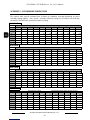
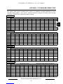
APPENDIX 3 - NV-DVR900 RECORDING TIME ...................................................................................84
APPENDIX 4 - NV-DVR1600 RECORDING TIME ..................................................................................85
TABLE OF CONTENTS

NV-DVR900 / NV-DVR1600 ver. 2.0 - User’s Manual
All rights reserved © NOVUS Security Sp. z o.o.
6
1. FOREWORD INFORMATION
Digital Multiplexer NV-DVR900 (9 channels) and NV-DVR1600 (16 channels) was specifically
designed to work in CCTV surveillance systems. This devices incorporate the advantages of digital
image recording with the simplicity of installation and operation of time lapse recorders. This devise
utilizes very effective compression method Wavelet, ensuring high quality, detailed images. This
devices provide function of high quality image recording over long periods of time. This series
of Multiplexer feature flexible adjustment of recording settings depending on individual system
requirements. This devices are also available in versions NV-DVR900CD and NV-DVR1600CD
with built in CD writers.
The ability to connect external devices to Multiplexer provides wide range of data backup options
and additionally the overall CCTV system functionality can be improved.
1.1 Main characteristic.
User friendly interface, with functions known from analog Multiplexers.
Convenient to use Shuttle / Jog system for data search.
The simplicity and convenience of using HDD instead of video tapes.
Immediate access to required stored material through advanced search functions.
Multilanguage OSD (On Screen Display) System Menu .
Multilevel user access and password protection system.
Remote Multiplexer control, image viewing and PTZ operation over Ethernet network (TCP/IP).
Pre/Post Alarm Function.
Wavelet compression algorithm with adjustable image quality settings.
Recording speed of 100 fields per second.
Schedule recording featuring integration of different recording modes.
RS-485 communication port for PTZ cameras remote control.
One real time audio channel recording.
Simultaneous real time display of all channels.
Adjustable resolution and recording speed defined individually for each camera and for different
recording modes.
Data backup option utilizing swappable drive, CD (depending on device version) or USB storing
devices.
FOREWORD INFORMATION

NV-DVR900 / NV-DVR1600 ver. 2.0 - User’s Manual
All rights reserved © NOVUS Security Sp. z o.o.
7
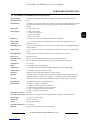
1.2. NV-DVR900 / NV-DVR900CD Technical Specification
Operation Mode: Quadroplex (simultaneous recording, live display, data playback and network connection)
Operation System : Linux
PTZ Functions: The ability to control PTZ cameras (Novus, Pelco, LG and others) utilizing Multiplexer without
the need to use additional keyboard, or through computer network utilizing Multi Viewer
software
Video Inputs: 9 x BNC, 1Vp-p, 75 Ω
Video Outputs: 1 x BNC –main monitor
1 x S-video - main monitor
1 x VGA - main monitor
1 x BNC - Call monitor
Resolution: 720 x 288, 360 x 288 (PAL), defined individually for each channel
Display Modes: 1, 4, 6, 8, 9, PiP, sequence, user defined, digital zoom, of selected image field x2, x3, x4
Compression: Wavelet (7 levels)
Recording Speed: from 1 frame/h up to 50 frames/s (100 frames/s for resolution 360 x 288), defined individually
for each channel
Display Speed: up to 25 frames per second for each channel (up to 225 frames per second for 9 channels split
screen)
Recording Modes: normal (continuous), schedule, alarm and/or motion detection event activation
Data Search: time/date or event
Motion Detection: grid 16x16, with adjustable sensitivity settings (specific for each camera)
Event List: up to 25 000 events (video loss detection, power loss, disk full, motion detection)
Alarm Inputs: 9 TTL inputs
Relays: 4 relay outputs (alarm) fully adjustable
Audio Inputs: 1 mono input cinch type, enhancing regulated in Multiplexer menu, sampling 8kHz
Audio Outputs: 1 mono output cinch type, signal level -5dB
Operation: front panel, remote control IR (included), computer network
Schedule: individual settings for each day of the week, individual settings for each camera, individual
settings for specific, exceptional days (holidays, etc.), different recording modes integration ,
CD writer: built in (version CD), external connected through USB port or IEEE1394 port (FireWire)
Image Backup: CD, HDD, USB devices, via computer network
External Ports: 1 x Ethernet - joint RJ-45, 10Mbit/sek,
1 x USB for external memory drives connection
1 x IEEE1394 for external memory drives connection
1 x RJ45 - for Speed Dome Cameras connection
2 x RJ45 - for system keyboard control
„Watch Dog” Function: hardware
Password Authorization: multilevel user accounts access and password protection, separate network passwords
Power Supply: 115-230 V AC, 55 W (±25%)
Dimensions: 432 x 88 x 430 mm
Weight: 8,2 kg (without HDD)
Operating Temperature: 0°C do +40°C
Humidity: 10-80% of relative humidity (without condensation)
FOREWORD INFORMATION

NV-DVR900 / NV-DVR1600 ver. 2.0 - User’s Manual
All rights reserved © NOVUS Security Sp. z o.o.
8
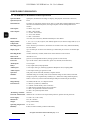
1.3. NV-DVR1600 / NV-DVR1600CD Technical Specification
Operation Mode: Quadroplex (simultaneous recording, live display, data playback and network connection)
Operation System : Linux
PTZ Functions: The ability to control PTZ cameras (Novus, Pelco, LG and others) utilizing Multiplexer without
the need to use additional keyboard, or through computer network utilizing Multi Viewer
software
Video Inputs: 16 x BNC, 1Vp-p, 75 Ω
Video Outputs: 1 x BNC –main monitor
1 x S-video - main monitor
1 x VGA - main monitor
1 x BNC - Call monitor
Resolution: 720 x 288, 360 x 288 (PAL), defined individually for each channel
Display Modes: 1, 4, 6, 8, 9, 13, 16, PiP, sequence, user defined, digital zoom, of selected image field x2, x3, x4
Compression: Wavelet (7 levels)
Recording Speed: from 1 frame/h up to 50 frames/s (100 frames/s for resolution 360 x 288), defined individually
for each channel
Display Speed: up to 25 frames per second for each channel (up to 400 frames per second for 16 channels split
screen)
Recording Modes: normal (continuous), schedule, alarm and/or motion detection event activation
Data Search: time/date or event
Motion Detection: grid 16x16, with adjustable sensitivity settings (specific for each camera)
Event List: up to 25 000 events (video loss detection, power loss, disk full, motion detection)
Alarm Inputs: 16 TTL inputs
Relays: 4 relay outputs (alarm) fully adjustable
Audio Inputs: 1 mono input cinch type, enhancing regulated in Multiplexer menu, sampling 8kHz
Audio Outputs: 1 mono output cinch type, signal level -5dB
Operation: front panel, remote control IR (included), computer network
Schedule: individual settings for each day of the week, individual settings for each camera, individual
settings for specific, exceptional days (holidays, etc.), different recording modes integration ,
CD writer: built in (version CD), external connected through USB port or IEEE1394 port (FireWire)
Image Backup: CD, HDD, USB devices, via computer network
External Ports: 1 x Ethernet - joint RJ-45, 10Mbit/sek,
1 x USB for external memory drives connection
1 x IEEE1394 for external memory drives connection
1 x RJ45 - for Speed Dome Cameras connection
2 x RJ45 - for system keyboard control
„Watch Dog” Function: hardware
Password Authorization: multilevel user accounts access and password protection, separate network passwords
Power Supply: 115-230 V AC, 55 W (±25%)
Dimensions: 432 x 88 x 430 mm
Weight: 8,2 kg (without HDD)
Operating Temperature: 0°C do +40°C
Humidity: 10-80% of relative humidity (without condensation)
FOREWORD INFORMATION

NV-DVR900 / NV-DVR1600 ver. 2.0 - User’s Manual
All rights reserved © NOVUS Security Sp. z o.o.
9
2. DEVICE POWER UP
2.1 Preparing the equipment for operation.
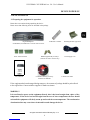
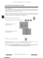
Please take extra caution during unpacking the device.
Please ensure that following items are included in the package
If the equipment has been damaged during transport , the contents of package should be packed back
to the original box. Contact with the supplier for further assistance.
WARNING !
It is not allowed to power on the equipment directly after it has been brought from a place of low
temperature. If the device has been brought from the area of lower temperature the user should
wait until the equipment will slowly warm up and reach the room temperature. The condensation
of moisturized air may cause short circuit and in result damage the device.
Digital Multiplexer
NV-DVR900, NV-DVR1600 or versions with CD writer
IR Remote Controller Mounting Brackets type Rack
HDD Swappable Bay lock-keys
(without CD writer versions only)
Power Supply cord
Screw Joints Terminals
4 rubber base stands CD-ROM containing necessary
Software and Manuals
DEVICE POWER UP
NV-DVR900
NV-DVR900CD
NV-DVR1600
NV-DVR1600CD
U s e r ’ s M a n u a l
User’s Manual

NV-DVR900 / NV-DVR1600 ver. 2.0 - User’s Manual
All rights reserved © NOVUS Security Sp. z o.o.
10
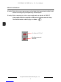
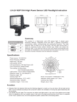
Warning: Before device power up user must read and heed all the instructions described in this
manual concerning back panel inputs usage and description.
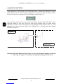
Warning: Before connecting the device to power supply make sure that the AC SELECT
voltage supply switch is set properly according to the local power network voltage.
This switch is marked on the next page as a number .
14
For Power of 115V AC
For Power network
230V AC
DEVICE POWER UP

NV-DVR900 / NV-DVR1600 ver. 2.0 - User’s Manual
All rights reserved © NOVUS Security Sp. z o.o.
11
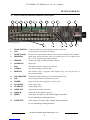
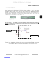
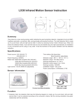
1. RS-422 (PORT A): two RS-422 ports for system keyboard (currently unavailable)
2. LAN : port designed for local network connection
3. RS-485 (Port B): RS-485 port for Speed Dome Cameras control connection working in this standard
4. SENSOR IN: alarm inputs, which from menu can be set normal open (N.O.) or normal closed
(N.C.), 16 or 9 depending on model purchased
5. IEEE1394: FireWire port input for additional HDD connection
6. ALARM OUT: alarm relays
7. VGA: main monitor output in VGA mode (computer)
8. S-VIDEO: main monitor output in S-Video mode
9. MONITOR: main monitor output , Composite Video Signal (CVS); user can select one of
various display modes.
10. CALL MONITOR: call monitor output (additional), CVS; only full display mode.
11. FAN device cooling ventilator it should not be covered
12. POWER: power on switch, when in position „1” device is ON
13. AC115/230V: power supply socket
14. AC SELECT: voltage supply switch
15. AUDIO OUT: audio output for speaker connection
16. AUDIO IN: audio input for microphone connection
17. INPUT: video inputs for cameras video channel signal connection,
16 or 9 depending on model purchased
17. LOOP OUT: video outputs for cameras video channel signal connection,
16 or 9 depending on model purchased
2.2 Electric connectors and other components of back panel
10
9 8 7 5 4 6 1 2 3 11 12
13
18 17 16 15 14
View of NV-DVR1600
DEVICE POWER UP

NV-DVR900 / NV-DVR1600 ver. 2.0 - User’s Manual
All rights reserved © NOVUS Security Sp. z o.o.
12
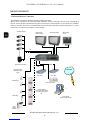
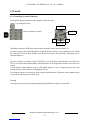
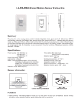
2.3 External Devices Connection
All installation procedures should be made by qualified personnel.
Before device installation and operation please familiarize with the schematics shown below. Depending on
specific user needs and requirements each system will consist of various number of external devices. Monitors,
cameras and other devices are not included and must be purchased separately. Detailed description of devices
connection is included in later chapter’s of this manual..
Alarm
System
Modules
LAN / WAN
Main Monitor
(BNC/S-Video)
Call Monitor (BNC) Main Monitor
(VGA)
RS-485
Video
Standard cameras
Speed Dome Cameras
PC computers
Provide remote viewing
External devices
connected to alarm
inputs
PIR detectors
Reed relays
External devices
connected to alarm relays
e.g. light signals, sirens
etc..
EXT. HDD
USB
FireWire
EXT. HDD
External CD writer
DEVICE POWER UP

NV-DVR900 / NV-DVR1600 ver. 2.0 - User’s Manual
All rights reserved © NOVUS Security Sp. z o.o.
13
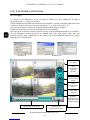
1. OPERATE Multiplexer power ON/OFF button. To power ON/OFF the device
press and hold for 3 seconds.
2. CHANNEL Channel selection switch. If one of these buttons is pressed the
corresponding camera video channel will be displayed. The images
will be displayed in full mode. Pressing these buttons in sequence
mode will display in succession different modes of split screen
display.
3.
3. SETUP Multiplexer settings enter buttons. OSD (On Screen Display) menu
will appear (description-chapter 3).
4. PANORAMA 9 or 16 images (from one camera) displayed in succession will
be displayed if this button is pressed. Individual frames are
displayed in one of the split screen window.
2.4 Front Panel description
1 2 3 4 5 6 7
10
8
15 14 13 12 11 16 17 18 9
View for NV-DVR1600
NV-DVR900
NV-DVR1600
DEVICE POWER UP

NV-DVR900 / NV-DVR1600 ver. 2.0 - User’s Manual
All rights reserved © NOVUS Security Sp. z o.o.
14
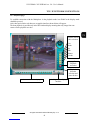
5. ZOOM Digital zoom button. Blue square will appear on the screen when
this button is pressed. This square specifies the zoom area.
If this button is pressed repeatedly the selected area of the image
will be enlarge by 2, 3, and 4 - times and finally it will exit the
zoom mode. To move the selected image zoom area the following
arrow buttons should be used
PANORAMA
,
AUTO
,
TRIPLEX
,
FREEZE
)
6. AR RESET Alarm reset buttons (only if menu settings allow this option)
/ AUTO
Additionally during live display mode pressing this button
activates camera sequence display on main monitor. Current
Multiplexer status is indicated by a light diode placed just above
the button.
7. TRIPLEX In the data playback mode this button turns on simultaneously
live display mode of one of the camera channels. One camera
channel is in live display in full screen mode while other camera
image is playback in a small window.
8. FREEZE This button allows to „FREEZE” selected camera image in live
display and playback modes. In order to use „FREEZE” function
the button
FREEZE
should be pressed (the light diode above the
button will turn on). Then select desired camera using numeric
button. One or multiple cameras can be selected. To disable
“FREEZE” function press the numeric button again. The sign
FR
indicates that current camera channel is in freeze mode. To disable
FREEZE function press the
FREEZE
button again. When
FREEZE option is disabled the light diode will turn off.
DEVICE POWER UP

NV-DVR900 / NV-DVR1600 ver. 2.0 - User’s Manual
All rights reserved © NOVUS Security Sp. z o.o.
15
9. HDD SWAPPABLE BAY Power off the device before taking out or putting in the HDD. To
open/lock the HDD swappable bay use lock keys included in the
package. The swappable bay is not included in versions with CD
writers
10. SHUTTLE This SHUTTLE knob is used to increase the playback speed
(fast forward / fast reverse) Depending on twist angle the playback
speed is changed.
JOG This function is used to decrease the playback speed.
In configuration mode it is used to move around the menu and for
characters selection.
11.
PLAY / ENTER This button activates playback menu. Playback mode is indicated
by light diode placed above the button.. In playback mode this
buttons allows to select the playback direction „forward”. By
pressing again the Multiplexer will switch into PAUSE mode
In configuration mode this button is assigned as a
ENTER
and it is
used to enter settings and edition fields.
12.
REV.PLAY / EXIT In the playback mode this button allows to select playback
direction „reverse”. By pressing again the Multiplexer will switch
into PAUSE mode.
In configuration mode this button is assigned as a
EXIT
and it is
used to exit edition fields and menu.
13. STOP In the playback mode this button is used stop the playback.
14. REC This button is used to switch to “manual recording mode” with
settings different then those in schedule recording. The light diode
placed above this button indicates that Multiplexer is currently
in manual recording mode. During schedule recording it is not
possible to activate manual recording mode.
15. DISPLAY Buttons grouped in section
DISPLAY
allow to select desired image
split screen display mode. Pictographs under the buttons describe
the type of split screen display mode.
Button allows to turn on user’s display modes (the light diode
above the button will turn on)
Individual layouts within selected mode are selected by numeric
buttons.
In playback mode three buttons have double function. For
detailed functions
CIF/FULL
,
AUTO
and COPY description please
see chapters 5 and 6)
U
NV-DVR900
NV-DVR1600
DEVICE POWER UP

NV-DVR900 / NV-DVR1600 ver. 2.0 - User’s Manual
All rights reserved © NOVUS Security Sp. z o.o.
16
16. SIGNAL DIODES Diode marked as a HDD indicates HDD’s status . LAN diode indicates
computer network connection
17. IR RECEIVER: The infra red receiver window emitted by IR remote Control.
Do not block.
18.
USB: USB input allowing to connect external drive.
DEVICE POWER UP

NV-DVR900 / NV-DVR1600 ver. 2.0 - User’s Manual
All rights reserved © NOVUS Security Sp. z o.o.
17
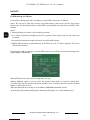
2.5 Device Power On/Off
When we are certain that the AC SELECT voltage supply selection switch is set in proper position
(see page 10 for more information) we can turn on the device with the switch (to position „1”).
To activate the Multiplexer the button
OPERATE
should be pressed and hold for around 3 seconds.
The system start procedure will initiate what will be indicated by a blinking diodes on front panel and
sign on the monitor screen.
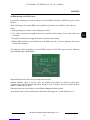
System Load Procedure takes dozen seconds. While its duration none of the front panel buttons or IR
Remote Control buttons should be pressed. System Load Procedure is finished if on the main monitor
screen camera images will appear along with their descriptions and system time will be displayed.
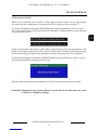
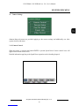
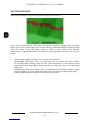
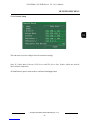
To deactivate the Multiplexer the button
OPERATE
should be pressed and hold for around 3 seconds.
The following information will appear on the screen.
When this information disappears the Multiplexer can be disconnected from the power network.
WARNING: Shutting down the system in different way then the one described above may result
in data loss or Multiplexer damage.
DEVICE POWER UP

NV-DVR900 / NV-DVR1600 ver. 2.0 - User’s Manual
All rights reserved © NOVUS Security Sp. z o.o.
18
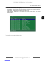
MULTIPLEXER MENU
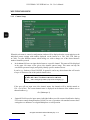
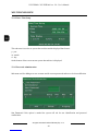
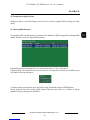
3. MULTIPLEXER MENU
Multiplexers NV-DVR900 and NV-DVR1600 provide multilevel OSD (on screen display) menus. This
menus provide Multiplexer’s settings functions and functions executions such us playback or backup.
Devices in versions with installed CD writers are identical in their functionality and feature identical
OSD.
The menu is displayed in English language however there is a possibility to select different language
(see chapter 3.6 fro more details).
Menu for devices in 9 and 16 channels versions vary only with the quantity of specific positions
applying to several channels. So there is 9, or 16 channels, alarm inputs, etc.
In order to enter Multiplexer menu settings button
SETUP
should be pressed.
In main menu that will be displayed on the screen there are seven sub-menus. Specific menu functions
will be described on next pages of this user’s manual.
To move around the menu
JOG
or buttons with arrows are used.
For selection confirmation, entering sub-menu as well as entering the edition fields button
ENTER
is used. When edition field is entered it is distinguish by an underline..
By twisting
JOG
or using arrow buttons the value is modified.
Exiting the menu will confirm and accept the inputted changes. In extraordinary events the system
requires reboot what will be notified by a system information window.
To exit the menu or to exit (come back) to a level higher from specific sub-menus end edition fields
button
EXIT
is utilized.
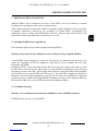
Some of the system settings modifications require longer periods of time to set. During this process
the user will be notified by a twisting sand-glass sign

NV-DVR900 / NV-DVR1600 ver. 2.0 - User’s Manual
All rights reserved © NOVUS Security Sp. z o.o.
19
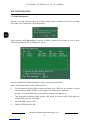
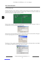
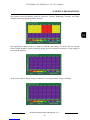
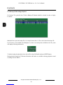
3.1 Camera Settings
Camera Setup
sub-menus are provided applying to the camera settings and additionally one video
system selection sub-menu.
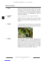
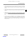
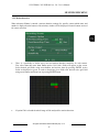
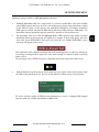
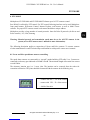
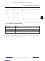
3.1.1 Camera Control
When this menu is selected and button
ENTER
is pressed Speed Dome Camera control icons will
appear on the bottom of the screen.
Detailed information applying to the Speed Dome operation can be founding chapter 8.
MULTIPLEXER MENU

NV-DVR900 / NV-DVR1600 ver. 2.0 - User’s Manual
All rights reserved © NOVUS Security Sp. z o.o.
20
MULTIPLEXER MENU
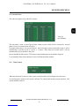
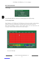
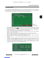
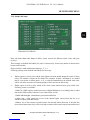
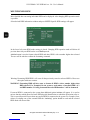
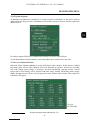
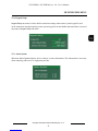
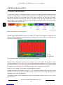
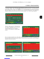
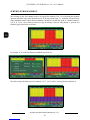
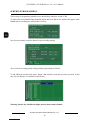
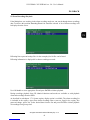
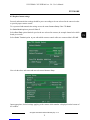
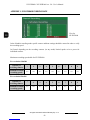
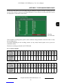
3.1.2 Camera Setup
When this sub-menu is entered a configuration window will be displayed on the screen applying to the
individual camera settings with number displayed on the bottom as a Ch1, Ch2....Ch9 (and up
to Ch16). To select different camera which settings we wish to change one of the desired numeric
numbers should be pressed.
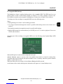
•In the
Name
field user can input desired name to a specific channel. This name will be displayed
in the upper left corner of the given video channel camera image. This name can help the
surveillance personnel simply and quickly identify specific monitored areas.
It can be e.g.: Stairways, Door2, HOUSE. In general it can be any desired name that will consist
of up to 16 characters out of the symbols shown below:
If the user will not input own video channel names the channels will be default named as:
Ch1....Ch9 (Ch16). The current channel name is displayed on the bottom of the window next to
channel number e.g..
Ch1 (Stairways. 3)
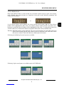
•
Control ID
field is used to input camera individual address used for camera identification during
PTZ remote control through interface RS-485. In case of operation with standard cameras these
settings have no influence over digital Multiplexer overall operation.
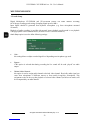
Spacja ! “ # $ % & ’ ( ) ” + , - . / 0 1 2 3 4 5 6 7 8 9 : ; < = > ?
@ A B C D E F G H I J K L M N O P Q R S T U V W X Y Z
[ ?] ^ _ ’ a b c d e f g h I j k l m n o p q r s t u v w x y z { | } ~
Page is loading ...
Page is loading ...
Page is loading ...
Page is loading ...
Page is loading ...
Page is loading ...
Page is loading ...
Page is loading ...
Page is loading ...
Page is loading ...
Page is loading ...
Page is loading ...
Page is loading ...
Page is loading ...
Page is loading ...
Page is loading ...
Page is loading ...
Page is loading ...
Page is loading ...
Page is loading ...
Page is loading ...
Page is loading ...
Page is loading ...
Page is loading ...
Page is loading ...
Page is loading ...
Page is loading ...
Page is loading ...
Page is loading ...
Page is loading ...
Page is loading ...
Page is loading ...
Page is loading ...
Page is loading ...
Page is loading ...
Page is loading ...
Page is loading ...
Page is loading ...
Page is loading ...
Page is loading ...
Page is loading ...
Page is loading ...
Page is loading ...
Page is loading ...
Page is loading ...
Page is loading ...
Page is loading ...
Page is loading ...
Page is loading ...
Page is loading ...
Page is loading ...
Page is loading ...
Page is loading ...
Page is loading ...
Page is loading ...
Page is loading ...
Page is loading ...
Page is loading ...
Page is loading ...
Page is loading ...
Page is loading ...
Page is loading ...
Page is loading ...
Page is loading ...
Page is loading ...
Page is loading ...
Page is loading ...
Page is loading ...
-
 1
1
-
 2
2
-
 3
3
-
 4
4
-
 5
5
-
 6
6
-
 7
7
-
 8
8
-
 9
9
-
 10
10
-
 11
11
-
 12
12
-
 13
13
-
 14
14
-
 15
15
-
 16
16
-
 17
17
-
 18
18
-
 19
19
-
 20
20
-
 21
21
-
 22
22
-
 23
23
-
 24
24
-
 25
25
-
 26
26
-
 27
27
-
 28
28
-
 29
29
-
 30
30
-
 31
31
-
 32
32
-
 33
33
-
 34
34
-
 35
35
-
 36
36
-
 37
37
-
 38
38
-
 39
39
-
 40
40
-
 41
41
-
 42
42
-
 43
43
-
 44
44
-
 45
45
-
 46
46
-
 47
47
-
 48
48
-
 49
49
-
 50
50
-
 51
51
-
 52
52
-
 53
53
-
 54
54
-
 55
55
-
 56
56
-
 57
57
-
 58
58
-
 59
59
-
 60
60
-
 61
61
-
 62
62
-
 63
63
-
 64
64
-
 65
65
-
 66
66
-
 67
67
-
 68
68
-
 69
69
-
 70
70
-
 71
71
-
 72
72
-
 73
73
-
 74
74
-
 75
75
-
 76
76
-
 77
77
-
 78
78
-
 79
79
-
 80
80
-
 81
81
-
 82
82
-
 83
83
-
 84
84
-
 85
85
-
 86
86
-
 87
87
-
 88
88


Novus NV-DVR1600CD User manual
- Category
- Digital Video Recorders (DVR)
- Type
- User manual
- This manual is also suitable for
Ask a question and I''ll find the answer in the document
Finding information in a document is now easier with AI
Related papers
-
Novus NV-DVR1116/CD User manual
-
-
-
-
-
-
Novus NVR-6316P16-H2 User manual
-
-
-
Other documents
-
 Okina USA VA122BNC Owner's manual
-
 Lexing LX-LD-102P118-24 Operating instructions
-
 Lexing LX-LD-102P118-9 Operating instructions
-
Patton electronics 6103 User manual
-
 Lexing LX38 Operating instructions
-
 Lexing LX-PR-21B Operating instructions
-
 Lexing LX118B Operating instructions
-
 Lexing LX-PR-21C Operating instructions
-
 Lexing LX-MV-360S18 Operating instructions
-
 Lexing LX48A Operating instructions


