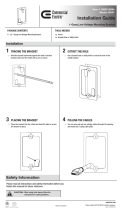
Remove the Touch Screen
To remove the touch screen after installation, carefully pull the touch
screen away from the wall until it disengages from the mounting
bracket.
To remove the touch screen if the security latch has been installed:
1. Pull the touch screen away from the wall until the security latch
makes contact with the mounting bracket.
2. Insert a flat-head screwdriver into the slot on the security latch
and rotate the latch into the open position, which retracts the
security latch arms.
3. With the arms retracted, pull on the touch screen to disengage it
from the mounting bracket.
Security
latch
bracket
(top view)
Touch
screen
Insert the
screwdriver
NOTE: There is a small amount of “play” in the bracket mounting, which
allows room to insert the screwdriver.
Configure the Device
When power is applied for the first time, the following screen is
displayed. The touch screen may take up to two minutes to boot.
Touch the screen to display the main Setup screen (TSW-1060 shown).
Device settings for the touch screen may be configured using the
built-in setup screens or the web configuration interface. For more
information on configuring the touch screen, refer to the
TSW-560/TSW-760/TSW-1060 Supplemental Guide (Doc. 7927)
at www.crestron.com/manuals.
Access the Device Setup Screens
To access the built-in setup screens for configuring device settings, do
either of the following:
• Place five fingers on the display and hold for 15 seconds.
• Press the hard keys labeled in the illustration below as 1, 2, 3, and
4 twice, in this sequence, within five seconds.
4
3
2
1
Use the setup screens to configure various settings for the touch
screen, including Ethernet setup, IP table setup, audio setup, display
setup, standby timeout, and diagnostics.
Access the Web Configuration Interface
The touch screen also provides a web configuration interface that is
used to view and configure various touch screen settings and to select
an application. The interface can be accessed using the touch screen IP
address or the Crestron XiO Cloud™ service.
Touch Screen IP Address
To access the web configuration interface using the touch screen IP
address:
1. Ensure that the touch screen is connected to the network.
2. Use the Device Discovery tool in Crestron Toolbox™ software to
discover the touch screen and its IP address on the network.
3. Enter the touch screen IP address into a web browser.
Crestron XiO Cloud Service
The Crestron XiO Cloud service allows supported Crestron devices
across an enterprise to be managed and configured from one central
and secure location in the cloud. Supported devices are configured to
connect to the service. Use of the service requires a registered
Crestron XiO Cloud account.
NOTE: The device may be disconnected from the service by navigating
to the Cloud Services tab in Crestron Toolbox software (Functions >
Device Info > Cloud Services). For details, refer to the Crestron Toolbox
help file.
To access the web configuration interface using the Crestron XiO Cloud
service:
1. Record the MAC address and serial number that are labeled on
the shipping box or rear panel of the device. The MAC address and
serial number are required to add the device to the service.
2. Do either of the following:
• For existing accounts, access the Crestron XiO Cloud service
at https://portal.crestron.io.
• For new accounts, register for a Crestron XiO Cloud account
at www.crestron.com/xio-cloud-registration.
3. Claim the device to the service as described in the Crestron XiO
Cloud User Guide (Doc. 8214) at www.crestron.com/manuals.
4. Select the device from the cloud interface to view its settings.
Set the Time Zone
The time zone must be set on the touch screen if it will not be paired
with a control system IP table.
To set the time zone:
1. Access the web configuration interface using either the touch
screen IP address or the Crestron XiO Cloud service.
2. Navigate to Settings > Configure Date/Time.
3. Select the time zone where the touch screen will be used from the
Time Zone drop-down menu.
4. Click Save Changes on the top right of the screen.
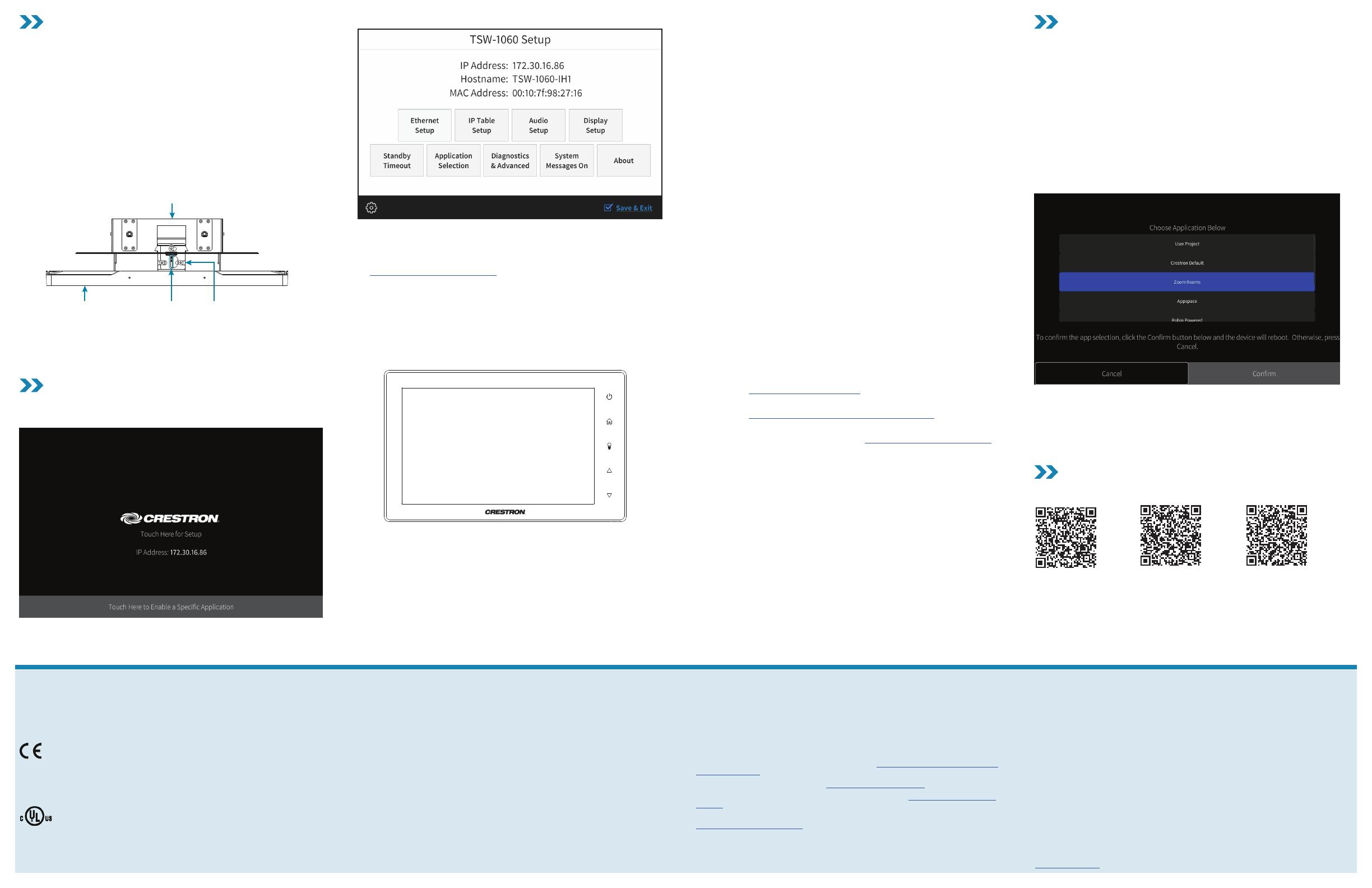
Select an Application
The touch screen ships with a selection of built-in applications. An
application may be selected from the splash screen that displays after
power is applied to the touch screen for the first time.
NOTE: Applications can be selected and configured from the device
setup screens or from the web configuration interface at any time. For
more information on configuring applications, refer to the
TSW-560/TSW-760/TSW-1060 Supplemental Guide (Doc. 7927).
To select a touch screen application:
1. Tap the Touch Here to Enable a Specific Application bar on the
bottom of the splash screen. Refer to the first image in the
“Configure the Device” section.
2. Select the desired touch screen application from the Choose
Application Below menu that is displayed.
3. Click Confirm. The touch screen reboots to display the user
interface for the selected application.
NOTE: If a custom user project will be used in place of an application,
tap User Project. Custom projects can be uploaded using the web
configuration interface or Crestron Toolbox software.
Additional Information
Scan or click the QR code for detailed product information.
TSW-560-B-S TSW-760-B-S TSW-1060-B-S
Compliance and Legal
Original Instructions: The U.S. English version of this document is the original instructions. All
other languages are a translation of the original instructions.
Regulatory Models: TSW-560 TSW-760 TSW-1060
As of the date of manufacture, the product has been tested and found to comply with
specifications for CE marking.
This product is Listed to applicable UL® Standards and requirements tested by Underwriters
Laboratories Inc.
Ce produit est homologué selon les normes et les exigences UL applicables par Underwriters
Laboratories Inc.
Federal Communications Commission (FCC) Compliance Statement
This device complies with part 15 of the FCC Rules. Operation is subject to the following
conditions: (1) This device may not cause harmful interference and (2) this device must accept
any interference received, including interference that may cause undesired operation.
CAUTION: Changes or modifications not expressly approved by the manufacturer responsible
for compliance could void the user’s authority to operate the equipment.
NOTE: This equipment has been tested and found to comply with the limits for a Class B
digital device, pursuant to part 15 of the FCC Rules. These limits are designed to provide
reasonable protection against harmful interference in a residential installation. This
equipment generates, uses and can radiate radio frequency energy and, if not installed
and used in accordance with the instructions, may cause harmful interference to radio
communications. However, there is no guarantee that interference will not occur in a
particular installation. If this equipment does cause harmful interference to radio or
television reception, which can be determined by turning the equipment off and on, the user is
encouraged to try to correct the interference by one or more of the following measures:
• Reorient or relocate the receiving antenna.
• Increase the separation between the equipment and receiver.
• Connect the equipment into an outlet on a circuit different from that to which the
receiver is connected.
• Consult the dealer or an experienced radio/TV technician for help.
Industry Canada (IC) Compliance Statement
CAN ICES-3 (B)/NMB-3(B)
Crestron product development software is licensed to Crestron dealers and Crestron Service
Providers (CSPs) under a limited non-exclusive, non-transferable Software Development
Tools License Agreement. Crestron product operating system software is licensed to Crestron
dealers, CSPs, and end-users under a separate End-User License Agreement. Both of these
Agreements can be found on the Crestron website at www.crestron.com/legal/software_
license_agreement.
The product warranty can be found at www.crestron.com/warranty.
The specific patents that cover Crestron products are listed at www.crestron.com/legal/
patents.
Certain Crestron products contain open source software. For specific information, please visit
www.crestron.com/opensource.
Crestron, the Crestron logo, Crestron Toolbox, Crestron XiO Cloud, Rava, and Smart Graphics
are either trademarks or registered trademarks of Crestron Electronics, Inc., in the United
States and/or other countries. UL and the UL logo are either trademarks or registered
trademarks of Underwriters Laboratories, Inc. in the United States and/or other countries.
Other trademarks, registered trademarks, and trade names may be used in this document to
refer to either the entities claiming the marks and names or their products. Crestron disclaims
any proprietary interest in the marks and names of others. Crestron is not responsible for
errors in typography or photography.
©2019 Crestron Electronics, Inc.
Crestron Electronics, Inc.
15 Volvo Drive, Rockleigh, NJ 07647
Tel: 888.CRESTRON
Fax: 201.767.7576
www.crestron.com
Quick Start - Doc. 7926F
(2053121)
06/07/19
Specifications subject to
change without notice