
0099001405-04
Model / Modelo / Modèle :
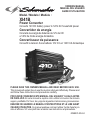
XI41B
Power Converter
Converts 12V DC battery power to 120V AC household power
Convertidor de energía
Convierte la energía de baterías de 12V de CD
a 120V de CA de energía doméstica
Convertisseur de puissance
Convertit la tension d’une batterie 12V CC en 120V CA domestique
OWNERS MANUAL
MANUAL DEL USUARIO
GUIDE D’UTILISATION
PLEASE SAVE THIS OWNERS MANUAL AND READ BEFORE EACH USE.
This manual will explain how to use the inverter safely and effectively. Please read
and follow these instructions and precautions carefully.
POR FAVOR CONSERVE ESTE MANUAL DEL USUARIO Y LEALO ANTES
DE CADA USO. En este manual le explica cómo utilizar el inversor de manera
segura y conable. Por favor, lea y siga las siguientes instrucciones y precauciones.
ESSAYER DE GARDER LE MANUEL D’INSTRUCTIONS ET LE LIRE AVANT
CHAQUE UTILISATION. Ce manuel explique comment utiliser l’unité d’une façon
sûre et efcace. S’il vous plaît lisez et suivez ces instructions et précautions.

CONTENTS
IMPORTANT SAFETY INSTRUCTIONS......................................................4
PERSONAL SAFETY PRECAUTIONS ........................................................ 5
BEFORE USING YOUR CONVERTER .......................................................5
FASTENING THE CONVERTER TO A FLAT SURFACE ............................. 7
CONNECTING CONVERTER CABLES ......................................................7
OPERATING INSTRUCTIONS ....................................................................8
POWER SOURCE .......................................................................................9
HOW POWER CONVERTERS WORK ........................................................ 9
LED INDICATOR AND SHUTDOWN PROTECTION ...................................9
IF A CONVERTER FUSE BLOWS .............................................................10
TROUBLESHOOTING ............................................................................... 11
SPECIFICATIONS .....................................................................................11
REPLACEMENT PARTS ............................................................................ 11
BEFORE RETURNING FOR REPAIRS ..................................................... 11
LIMITED WARRANTY ................................................................................12
WARRANTY CARD ....................................................................................33
CONTENIDOS
INSTRUCCIONES IMPORTANTES DE SEGURIDAD ..............................13
PRECAUCIONES DE SEGURIDAD PERSONAL ......................................14
ANTES DE USAR SU CONVERTIDOR .................................................... 14
PARA SUJETAR EL CONVERTIDOR A UNA SUPERFICIE PLANA .........16
PARA CONECTAR LOS CABLES DEL CONVERTIDOR ..........................16
INSTRUCCIONES DE OPERACIÓN ......................................................... 17
FUENTE DE ENERGÍA .............................................................................. 18
CÓMO FUNCIONAN LOS CONVERTIDORES DE CORRIENTE .............19
INDICADOR LED Y PROTECCIÓN DE DE APAGADO ............................19
SI SE QUEMA UN FUSIBLE EN EL CONVERTIDOR ...............................20
RESOLUCIÓN DE PROBLEMAS ..............................................................20
ESPECIFICACIONES ................................................................................21
PIEZAS DE REPUESTO ............................................................................ 21
ANTES DE DEVOLVER A REPARACIONES .............................................21
GARANTÍA LIMITADA ................................................................................21
TARJETA DE GARANTÍA ........................................................................... 34

TABLE DES MATIÈRES
CONSIGNES DE SÉCURITÉ IMPORTANTES ..........................................23
MESURES DE SÉCURITÉ PERSONNELLE .............................................24
AVANT D’UTILISER VOTRE CONVERTISSEUR ......................................24
FIXATION DE L’ONDULEUR SUR UNE SURFACE PLANE .....................26
CONNEXION DES CÀBLES DU CONVERTISSEUR ................................ 26
INSTRUCTIONS D’UTILISATION ..............................................................27
SOURCE D’ALIMENTATION .....................................................................28
COMMENT CONVERTISSEURS TRAVAIL ...............................................29
INDICATEUR DEL ET PROTECTION EN CAS DE COUPURE ................29
SI LE FUSIBLE DU CONVERTISSEUR SAUTE .......................................30
DÉPANNAGE .............................................................................................30
SPÉCIFICATIONS .....................................................................................30
PIÊCES DE RECHANGE ...........................................................................31
AVANT DE L’ENVOYER POUR RÉPARATIONS ....................................... 31
GARANTIE LIMITÉE .................................................................................. 31
CARTE DE GARANTIE .............................................................................. 35

• 4 •
1. IMPORTANT SAFETY INSTRUCTIONS
SAVE THESE INSTRUCTIONS.
1.1 SAVE THESE INSTRUCTIONS. This manual will show you how to use your converter
safely and effectively. Please read, understand and follow these instructions and
precautions carefully, as this manual contains important safety and operating instructions.
WARNING: The converter output is 120V AC and can shock or electrocute the
same as any ordinary household AC wall outlet.
1.2 Do not cover or obstruct the converter’s vents.
1.3 Use the converter in a well-ventilated area.
1.4 This converter is not intended for use by children.
1.5 Do not expose the converter to rain or snow.
1.6 Ensure that the converter is located away from normal trafc areas.
1.7 Use only accessories recommended or sold by the manufacturer.
1.8 Do not operate the converter with damaged or undersized wiring.
1.9 Do not operate the converter if it has received a sharp blow, been dropped or
otherwise damaged in any way; take it to a qualied service person.
1.10 Do not disassemble the converter; take it to a qualied service person when service
or repair is required. Incorrect reassembly may result in a risk of re or electric shock.
1.11 Make sure the converter is not close to any potential source of ammable fumes,
gases or clothing.
1.12 Do not place the converter in areas such as battery compartments or engine
compartments where fumes or gases may accumulate.
1.13 Disconnect both AC and DC power from the converter before attempting any cleaning.
1.14 DO NOT operate the converter if you, the converter, the device being operated or any
other surfaces that may come into contact with any power source are wet. Water and
many other liquids can conduct electricity, which may lead to serious injury or death.
1.15 Do not place the converter in direct sunlight. The ideal air temperature for
operation is between 50° and 80°F.
1.16 Only connect the power converter to a 12V accessory outlet or 12V battery.
1.17 Do not attempt to connect the converter to any other power source, including an AC
power source. Connecting to a 6V or 16V battery will cause damage to the converter.
1.18 Do not modify the USB port or AC receptacles in any way.
1.19 Do not try extending or otherwise changing the 12V power cord attached to your
converter.
1.20 Incorrect operation of your converter may result in damage and personal injury.
1.21 This device does not include an internal Ground Fault Circuit Interrupter (GFCI).
For GFCI protection, use a Coleman Cable 02822 GFCI outlet.

• 5 •
2. PERSONAL SAFETY PRECAUTIONS
2.1 Restrictions on Use: This converter may not be used with life support devices or
systems. Failure of this converter can reasonably be expected to cause failure of that life
support device or system, or to affect the safety or effectiveness of that device or system.
2.2 Wear complete eye and clothing protection when working near lead-acid batteries.
Always have someone nearby for help.
2.3 Remove all personal metal items from your body, such as rings, bracelets,
necklaces and watches. A lead-acid battery can produce a short circuit current
high enough to weld a ring to metal, causing a severe burn.
2.4 Never smoke or allow a spark or ame in the vicinity of the battery or engine.
3. BEFORE USING YOUR CONVERTER
• This converter is designed to be used with a single battery, up to group 31 (130
Ah or smaller). The recommended source of power is a 12 volt deep-cycle battery,
due to their high reserve capacity. Automotive batteries are recommended for only
a short period of time of an hour or less.
• Do not use the converter with a product that draws a higher wattage than the
converter can provide, as this may cause damage to the converter and product.
When you turn on a device or a tool that runs on a motor, the device goes through 2 stages:
1. Start Up – Requiring an initial surge of power (commonly known as the
“starting” or “peak” load).
2. Continuous Operation – Power consumption drops (commonly known as the
“continuous load”).
The wattage (WATTS) or amperes (AMPS) can normally be found stamped or
printed on most devices and equipment, or in the user’s manual. Otherwise, contact
the manufacturer to nd out whether the device you want to use is compatible with a
modied sine wave.
To calculate the wattage: Wattage = AMPS x 120 (AC Voltage).
To calculate the starting load: Starting Load = 2 x wattage.
In general, the startup load of the device or power tool determines whether your
converter has the capability to power it.
Always run a test to establish whether the converter will operate a particular piece of
equipment or device. In the event of a power overload, the converter is designed to
automatically shut down.
This safety feature prevents damaging the converter while testing devices and
equipment within the wattage range of the converter.

• 6 •
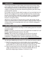
When using the vehicle’s 12 volt accessory port, this converter is designed to supply
60 to 70 watts when the vehicle is not running. With the vehicle’s engine running, it can
supply up to 100 watts. To use the full output, you must connect the converter directly
to your battery.
NOTE: The 100 watt limit is to accommodate the fuse ratings for all vehicles. Some
vehicles may allow the full output. If the fuse blows when you switch on the device
you are trying to use, you have to either use a smaller device or you must connect the
converter directly to the battery.
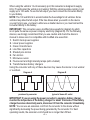
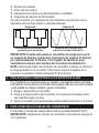
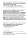
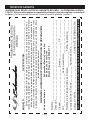
IMPORTANT: This converter uses a modied sine waveform (diagram A) which
is not quite the same as power company electricity (diagram B). For the following
devices, we strongly recommend that you use caution and check the device’s
manual to make sure it is compatible with modied sine waveform.
1. Switch mode power supplies
2. Linear power supplies
3. Class 2 transformers
4. Line lter capacitors
5. Shaded pole motors
6. Fan motors
7. Microwave ovens
8. Fluorescent and high intensity lamps (with a ballast)
9. Transformerless battery chargers
Using the converter with any of these devices may cause the device to run warmer
or overheat.
Modied sine waveform
produced by converter
Diagram A Diagram B
Pure sine waveform
typical of home AC outlet
IMPORTANT: If you are using the power converter to operate a battery charger,
monitor the temperature of the battery charger for about 10 minutes. If the battery
charger becomes abnormally warm, disconnect it from the converter immediately.
NOTE: You can use an extension cord from the converter to the device without
signicantly decreasing the power being generated by the converter. For best
operating results, the extension cord should be no longer than 50 feet.

• 7 •
4. FASTENING THE CONVERTER TO A FLAT SURFACE
For convenience, your converter can be fastened to a at surface, horizontally or
vertically. The area where the converter is to be fastened must be dry, well ventilated
and away from any combustible material or fumes.
1. Turn off and disconnect the converter.
2. Place the back of the converter with the mounting bracket against a secure and
at surface.
3. Attach the converter to the at surface using corrosion-resistant screws.
5. CONNECTING CONVERTER CABLES
The converter and power source must be in the OFF mode.
IMPORTANT: Make sure you connect your converter to a 12 volt power supply only.
CONVERTER CONNECTION:
1. Locate the positive and negative plastic terminals located on the right side of
the converter and remove the terminal caps completely.
2. Install the positive (red) cable ring lug onto the positive (red) terminal screw.
Install the negative (black) cable ring lug onto the negative (black) terminal
screw. Tighten each terminal so that the cable cannot come loose.
CONNECTING CONVERTER CABLE TO A VEHICLE (100 watts maximum):
1. Remove the cigarette lighter from its outlet.
2. Push the 12 volt power plug rmly into the outlet.
CONNECTING CONVERTER CABLES TO 12V BATTERY
OR 12V POWER SOURCE:
1. Keep hands, hair, clothing and jewelry clear of battery terminals.
2. Wear eye protection and protective clothing.
3. Connect the positive (red) converter terminal cable to the power source
positive (+) or battery terminal. Make sure the connection is secure.
4. Connect the negative (black) converter terminal cable to the power source
negative (-) or battery terminal. Make sure the connection is secure.
5. To disconnect the converter, reverse the above steps.
NOTE: The internal speaker may make a brief “beep” when the converter is being
connected to or disconnected from the 12V power source.
ATTENTION: Failure to make the correct connections will result in blown fuses and
permanent damage to the converter.

• 8 •
6. OPERATING INSTRUCTIONS
1. Connect the converter (see Connecting Converter Cables section).
2. Make sure the device to be operated is turned OFF.
3. Plug the device into the converter’s AC outlet.
4. Switch the converter’s ON/OFF switch to the ON position.
5. Turn the device on.
6. To disconnect, reverse the above procedure.
NOTE: If more than one device is to be powered, start one device at a time to avoid
a power surge and overloading the converter. The surge load of each device should
not exceed the converter’s Continuous Operation wattage rate.
USING THE CONVERTER TO OPERATE A TV OR AUDIO DEVICE:
The converter is shielded and ltered to minimize signal interference. Despite this,
some interference may occur with your television picture, especially with weak
signals. Below are some suggestions to try and improve reception.
1. Try altering the position of the converter, antenna cables, and television power
cord. Add an extension cord from the converter to the TV so as to isolate its
power cord and antenna cables from the 12 volt power source.
2. Try coiling the television power cord and the input cables running from the 12V
power source to the converter.
3. Afx one or several “Ferrite Data Line Filters” to the television power cord.
Ferrite Data Line Filters can be purchased at most electronic supply stores.
NOTE: You may hear a “buzzing” sound being emitted from inexpensive sound
systems when operated with the converter. This is due to ineffective lters in the
sound system’s power supply. Unfortunately, this problem can only be resolved by
purchasing a sound system with a higher quality power supply or higher quality lter.
USING THE USB PORT
The USB port provides up to 2A at 5V DC.
1. Plug the device into the USB port.
2. Turn the USB device on.
3. Reverse these steps when nished using the USB port.
WARNING: The converter draws power, even when the switch is OFF.
To avoid battery drain, disconnect the converter when not in use.

• 9 •
7. POWER SOURCE
Your average automobile or marine battery at full charge will provide an ample
power supply to the converter for approximately 3 hours when the engine is off.
The actual length of time the converter will function depends on the age and
condition of the battery and the power demand being placed by the device being
operated with the converter.
If you decide to use the converter while the engine is off, we recommend you turn
OFF the device plugged into the converter and disconnect the converter’s plug
from the 12 volt accessory outlet before starting the engine. To maintain battery
power, start the engine every 2 to 3 hours and let it run for approximately 10
minutes to recharge the battery.
Although it is not necessary to disconnect the converter when turning over the
engine, it may briey cease to operate as the battery voltage decreases. While the
converter draws very low amperage when not in use, it should be unplugged to
avoid battery drain.
8. HOW POWER CONVERTERS WORK
There are two stages involved in converting 12 volt DC (battery) power into 120 volt AC
(household voltage):
STAGE 1: The power converter uses a DC to DC transformer to increase the 12-volt
DC input voltage from the power source to 145 volt DC.
STAGE 2: The converter then converts the 145 volt DC into 120 volts AC
(household voltage) using advanced MOSFET transistors in a full bridge
conguration. A “modied sine wave” waveform is generated by this conversion.
9. LED INDICATOR AND SHUTDOWN PROTECTION
The LED glows GREEN when the switch is on, and under the following conditions:
1. When the power input from the vehicle’s battery drops to approximately
10 volts, low battery shutdown occurs and the converter shuts off. The Green
and Red LEDs are on, with a buzzer. Recharge or replace the battery.
2. When the power input from the vehicle’s battery exceeds 16±0.5 volts, high
voltage overload protection occurs. The Green and Red LEDs are on.
Reduce the voltage range to between 12 volts and 14 volts.

• 10 •
3. The continuous load demand from the equipment or device being operated
exceeds the continuous load rating of the converter being used. The Green
LED is on; the Red LED pulses.
Use a higher capacity converter or lower-rated device.
4. The case temperature becomes hot (exceeds 145°F). The Green and Red
LEDs are on, with a buzzer.
Allow the converter to cool. Do not block the cooling slots or air ow over and
through the converter. Reduce the load on the converter to the continuous
rated output.
RESET
To reset after shutdown occurs:
1. Disconnect the converter from the 12V power source.
2. Check the source of the problem and correct.
3. Reconnect the converter to the 12V power source.
NOTE: If the red LED is lit and the green LED is not, see Troubleshooting.
10. IF A CONVERTER FUSE BLOWS
Your power converter is tted with two fuses, which should not have to be replaced
under normal operating conditions. A blown fuse is usually caused by reverse
polarity or a short circuit within the device or equipment being operated.
If a fuse does blow:
1. Disconnect the device or equipment immediately.
2. Find the source of the problem and repair it.
3. Install a new fuse (25A). The fuse can be found on the back of the converter.
IMPORTANT: Do not install a fuse with a higher amp rating than the original fuse, as
this may damage the converter and any product you use with the converter. Make
sure to correct the cause of the blown fuse before using the converter again.

• 11 •
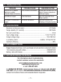
11. TROUBLESHOOTING
PROBLEM POSSIBLE CAUSE REASON/SOLUTION
Red LED is on, audible
alarm is on, and/or
converter does not function.
Poor contact at terminals. Unplug and reinsert the 12V
plug or check connections
at power supply.
No LEDs or output. Fuse has blown. See If a Converter Fuse
Blows section.
No output or intermittent
output.
Converter shutdown. See LED Indicator and
Shutdown Protection section.
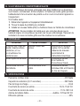
12. SPECIFICATIONS
Maximum continuous output ................................................................. 410 Watts
Surge capacity (0.1 second) ................................................................. 820 Watts
No load current draw ...................................................................................<0.6A
Input voltage range ..................................................................... 10.0V-15.0V DC
Output voltage range .....................................................................110V-125V AC
Low battery alarm ..........................................................Audible, 10.5V±0.5V DC
Optimum efciency ........................................................................................85%
13. REPLACEMENT PARTS
Fuses: Replacement fuses can be purchased at most electronic component retailers.
12V accessory plug with cables ......................................................3899003535Z
Battery cable with clamps ............................................................... 3899003533Z
14. BEFORE RETURNING FOR REPAIRS
For information about troubleshooting,
contact customer service for assistance:
www.batterychargers.com
or call 1-800-621-5485
For REPAIR OR RETURN, contact Customer Service at 1-800-621-5485. DO NOT
SHIP UNIT until you receive a RETURN MERCHANDISE AUTHORIZATION (RMA)
number from Customer Service at Schumacher Electric Corporation.

• 12 •
15. LIMITED WARRANTY
SCHUMACHER ELECTRIC CORPORATION, 801 E. BUSINESS CENTER DRIVE,
MOUNT PROSPECT, IL 60056-2179, MAKES THIS LIMITED WARRANTY TO THE
ORIGINAL RETAIL PURCHASER OF THIS PRODUCT. THIS LIMITED WARRANTY
IS NOT TRANSFERABLE OR ASSIGNABLE.
Schumacher Electric Corporation (the “Manufacturer”) warrants this converter
for one (1) year from the date of purchase at retail against defective material or
workmanship that may occur under normal use and care. If your unit is not free
from defective material or workmanship, Manufacturer’s obligation under this
warranty is solely to repair or replace your product with a new or reconditioned unit
at the option of the Manufacturer. It is the obligation of the purchaser to forward the
unit, along with proof of purchase and mailing charges prepaid to the Manufacturer
or its authorized representatives in order for repair or replacement to occur.
Manufacturer does not provide any warranty for any accessories used with this
product that are not manufactured by Schumacher Electric Corporation and
approved for use with this product. This Limited Warranty is void if the product is
misused, subjected to careless handling, repaired, or modied by anyone other
than Manufacturer or if this unit is resold through an unauthorized retailer.
Manufacturer makes no other warranties, including, but not limited to, express,
implied or statutory warranties, including without limitation, any implied warranty
of merchantability or implied warranty of tness for a particular purpose. Further,
Manufacturer shall not be liable for any incidental, special or consequential damage
claims incurred by purchasers, users or others associated with this product, including,
but not limited to, lost prots, revenues, anticipated sales, business opportunities,
goodwill, business interruption and any other injury or damage. Any and all such
warranties, other than the limited warranty included herein, are hereby expressly
disclaimed and excluded. Some states do not allow the exclusion or limitation of
incidental or consequential damages or length of implied warranty, so the above
limitations or exclusions may not apply to you. This warranty gives you specic legal
rights and it is possible you may have other rights which vary from this warranty.
THIS LIMITED WARRANTY IS THE ONLY EXPRESS LIMITED WARRANTY
AND THE MANUFACTURER NEITHER ASSUMES OR AUTHORIZES
ANYONE TO ASSUME OR MAKE ANY OTHER OBLIGATION TOWARDS
THE PRODUCT OTHER THAN THIS WARRANTY.
Schumacher
®
and the Schumacher logo are registered
trademarks of Schumacher Electric Corporation.
Page is loading ...
Page is loading ...
Page is loading ...
Page is loading ...
Page is loading ...
Page is loading ...
Page is loading ...
Page is loading ...
Page is loading ...
Page is loading ...
Page is loading ...
Page is loading ...
Page is loading ...
Page is loading ...
Page is loading ...
Page is loading ...
Page is loading ...
Page is loading ...
Page is loading ...
Page is loading ...

• 33 •
1 YEAR LIMITED
WARRANTY PROGRAM
REGISTRATION
MODEL: _____________________DESCRIPTION: ________________________
This is the only express limited warranty, and the manufacturer neither assumes
nor authorizes anyone to assume or make any other obligation. There is no other
warranty, other than what is described in the product owner’s manual.
The warranty card should be submitted within 30 days of purchase. The customer
must keep the ORIGINAL receipt because it will be required for any warranty claims.
This warranty is not transferable. Send warranty card only.
DO NOT SEND UNIT TO THIS ADDRESS FOR REPAIR.
Mail this card to: Schumacher Electric Corporation
801 Business Center Drive
Mount Prospect, IL 60056-2179
Name ______________________________________________________________
Street Address _______________________________________________________
City ________________________________State _________ Zip Code _________
Phone _____________________Email ___________________________________
Store Name Where Purchased ___________________ Date of Purchase _________
Store Location ____________________ UPC Number ________________________
Serial Number ______________________________________ (SEE PRODUCT)
For faster warranty activation, go to www.batterychargers.com to register your product online.
SAVE ON POSTAGE! ACTIVATE YOUR WARRANTY ONLINE – THE QUICK AND EASY WAY!
Go to www.batterychargers.com to register your product online.
(No internet access? Send in the completed warranty card.)
WARRANTY CARD
Page is loading ...
Page is loading ...
-
 1
1
-
 2
2
-
 3
3
-
 4
4
-
 5
5
-
 6
6
-
 7
7
-
 8
8
-
 9
9
-
 10
10
-
 11
11
-
 12
12
-
 13
13
-
 14
14
-
 15
15
-
 16
16
-
 17
17
-
 18
18
-
 19
19
-
 20
20
-
 21
21
-
 22
22
-
 23
23
-
 24
24
-
 25
25
-
 26
26
-
 27
27
-
 28
28
-
 29
29
-
 30
30
-
 31
31
-
 32
32
-
 33
33
-
 34
34
-
 35
35


Schumacher XI41BXI41B Owner's manual
- Type
- Owner's manual
- This manual is also suitable for
Ask a question and I''ll find the answer in the document
Finding information in a document is now easier with AI
in other languages
Related papers
-
Schumacher XI75B Power Converter Owner's manual
-
-
-
-
-
-
-
-
-
Other documents
-
909 HT8750-AUOXY User manual
-
Schumacher Electric PID-410 Owner's manual
-
Schumacher Electric SSF-1000A Owner's manual
-
-
 Nature Power 30058 User manual
-
RCA AH630R User manual
-
VOLTCRAFT SPA-5 Operating Instructions Manual
-
Sunforce 55510 User manual
-
-
Castorama Transformateur 100W 110-220V France/USA User guide
