Page is loading ...

User Instruction Manual Rescumatic® Emergency Escape
Device and Rescue Cradle
This manual is provided as the Manufacturer’s instructions, and should be used as
part of an employee training program as required by OSHA and CSA.
WARNING: This product is part of an emergency escape
system. The user must follow manufacturer’s instructions
for each part of this system. The user must read and
understand these instructions before using this equipment.
Manufacturer’s instructions must be followed for proper
use and maintenance of this equipment. Alterations or
misuse of this equipment, or failure to follow instructions,
may result in serious injury or death.
IMPORTANT: If you have questions on the use, care, or
suitability of this equipment for your application, contact
DBI/SALA.
IMPORTANT: Record the product identification information
from the ID label in the inspection and maintenance log in
section 9.0 of this manual.
DESCRIPTION
3300000 (SD-100): Rescumatic® Emergency Escape Device, includes two webbing body supports, one 2000106
carabiner, rope, styrene rope spool, and a vinyl dust cover.
9501722: Snatch Block; for angled descent. (Optional item, sold separately)
3610000: Rescue Cradle, this kit consists of a canvas cradle, a carabiner and a guide line. The cradle has one ring on
each side and a webbing tab tail which must all be attached together. (Optional item, sold separately)
1.0 APPLICATIONS
1.1 Purpose: The Rescumatic® Emergency Escape Device is used for automatic, controlled descent from overhead
cranes, towers, buildings or other heights. The system alternates from clockwise to counterclockwise from
descent to descent, thus allowing for multiple descents to occur. Rope lengths up to 1,000 ft (304.8m) (300 ft
[91.4m] in Canada) are available. The Snatch Block is used for angled descent when a vertical descent is
inappropriate due to fire, smoke, fumes, or other danger. See section 3.3 (C). The Rescue Cradle is used for a
rescue of an injured person. See section 3.4 (C).
IMPORTANT: The Rescumatic® Emergency Escape Device must not be used for fall protection. This equipment is
designed for EMERGENCY descent use only.
1.2 LIMITATIONS: Consider the following application limitations before using this equipment:
A. CAPACITY: The Rescumatic® is designed for use by persons with a combined weight (clothing, tools, ect.)
of 75 lbs. to 300 lbs (34kg to 136kg). (Rescue Cradle capacity is 350 lbs (159kg).)
Rescue Cradle
Rescumatic® Emergency
Escape Device
Snatch Block
Instructions for the following series products:
Rescumatic Emergency Escape Device
(See back page for specific model numbers.)
© Copyright 2008, DB Industries, Inc.

2
Figure 1 - Rescumatic® Emergency Escape Device
Rescumatic®
(labeling on face and sides)
Carabiner
D-ring
Body Support
Adjuustment
Buckle
Rope
Rope
Spool
Rope System
Label

3
B. DESCENT SPEED: The average speed at which the user will be lowered when using the Rescumatic®
Emergency Escape Device is 3 ft per second (.9m per second).
C. ENVIRONMENTAL HAZARDS: Use of this equipment in areas with environmental hazards may require
additional precautions to prevent injury to the user or damage to the equipment. Hazards may include, but
are not limited to; high heat, caustic chemicals, corrosive environments, high voltage power lines, explosive
or toxic gases, moving machinery, and sharp edges.
D. TRAINING: This equipment must be installed and used by persons trained in its correct application and use.
E. MAXIMUM SYSTEM LENGTH: The maximum length of descent is 1,000 ft (304.8m) (300 ft [91.4m] in
Canada). Special precautions in storing and unwinding the rope are required for all lengths over 250 ft (76.2m).
F. NUMBER OF USERS: The Rescumatic® Emergency Escape Device is used by one person at a time.
Multiple descents can be performed.
G. BODY SUPPORT: The webbing body support strap provided with the system provides limited support when
descending. For long descents, or if immediate descent is not mandatory, a full body harness is
recommended to help support and provide comfort to the user.
1.3 APPLICATION STANDARDS: Refer to applicable standards, including local, state, and federal requirements for
more information.
2.0 System Requirements
2.1 COMPATIBILITY OF COMPONENTS: DBI/SALA equipment is designed for use with DBI/SALA approved
components and subsystems only. Substitutions or replacements made with non-approved components or
subsystems may jeopardize compatibility of equipment and may effect the safety and reliability of the complete
system.
2.2 COMPATIBILITY OF CONNECTORS: Connectors are considered to be compatible with connecting elements
when they have been designed to work together in such a way that their sizes and shapes do not cause their
gate mechanisms to inadvertently open regardless of how they become oriented. Contact DBI/SALA if you have
any questions about compatibility.
If the connecting element that a snap hook (shown) or carabiner attaches to is undersized or irregular in
shape, a situation could occur where the connecting element applies a force to the gate of the snap hook or
carabiner. This force may cause the gate (of either a self-locking or a non-locking snap hook) to open,
allowing the snap hook or carabiner to disengage from the connecting point.
1. Force is applied to the
snap hook.
2. The gate presses against
the connecting ring.
3. The gate opens allowing the
snap hook to slip off.
Figure 2 - Unintentional Disengagement (Roll-out)
Small ring or other
non-compatibly
shaped element

4
Connectors ( hooks, carabiners, and D-rings) must be capable of supporting at least 5,000 lbs. (22.2kN).
Connectors must be compatible with the anchorage or other system components. Do not use equipment that is
not compatible. Non-compatible connectors may unintentionally disengage. See Figure 2. Connectors must be
compatible in size, shape, and strength. Self locking snap hooks and carabiners are required by ANSI Z359.1,
OSHA, and CSA Z259.12.
2.3 Making Connections: Only use self-locking snap hooks and carabiners with this equipment. Only use
connectors that are suitable to each application. Ensure all connections are compatible in size, shape and
strength. Do not use equipment that is not compatible. Ensure all connectors are fully closed and locked.
DBI/SALA connectors (snap hooks and carabiners) are designed to be used only as specified in each product’s
user’s instructions. See Figure 3 for inappropriate connections. DBI/SALA snap hooks and carabiners should not
be connected:
A. To a D-ring to which another connector is attached.
B. In a manner that would result in a load on the gate.
NOTE: Large throat opening snap hooks should not be connected to standard size D-rings or similar objects which
will result in a load on the gate if the hook or D-ring twists or rotates. Large throat snap hooks are designed for use on
fixed structural elements such as rebar or cross members that are not shaped in a way that can capture the gate of
the hook.
C. In a false engagement, where features that protrude from the snap hook or carabiner catch on the anchor
and without visual confirmation seems to be fully engaged to the anchor point.
D. To each other.
E. Directly to webbing or rope lanyard or tie-back (unless the manufacturer’s instructions for both the lanyard
and connector specifically allows such a connection).
F. To any object which is shaped or dimensioned such that the snap hook or carabiner will not close and lock,
or that roll-out could occur.
2.4 ANCHORAGE
STRENGTH:
Anchorages selected
for the Rescumatic®
Emergency Escape
Device shall have a
strength capable of
sustaining static
loads, applied in the
directions permitted by
the rescue system of
at least 3100 lbs
(13.8kN) for
connection of rescue
system only, or meet a
factor safety of 5:1
based on the static
load placed on the
system when the
system is designed,
installed and used
under the supervision
of a Qualified Person, as per OSHA definition. The anchorage point should be as close as possible to a vertical
descent path. No more than one Rescumatic® Device may be connected to a single anchorage. Anchorages used
to support a guide cable, when applicable, must be sufficiently strong to withstand the forces generated in the
guide cable during descent. See section 3.3 (C).
Figure 3 - Inappropriate Connections

5
2.5 MOUNTING: The Rescumatic® Emergency Escape Device unit can be mounted permanently or temporarily with
the carabiner provided to a anchorage point.
2.6 ANCHORAGE LOCATION: It is recommended that the anchorage point be approximately seven feet above
standing level and close to the escape point. The anchorage location should provide for a safe mounting and
descent without exposing the user to a fall hazard or other hazards.
2.7 ENVIRONMENTAL HAZARDS: The Rescumatic® Emergency Escape Device should be protected from the
effect of weather and the environment as follows:
Outdoors
A protective box should be constructed to suit local conditions. The box should be dry, resistant to salt spray,
wind, fumes and UV light. All outdoor locations shall be arranged so the Rescumatic® Emergency Escape
Device can be easily taken from it’s dry protective encloser and suspended from the fixture by means of the
carabiner. DBI/SALA offers a permanent mount storage cabinet, part number 9501721.
Indoors
For dusty locations indoors, all permanently installed Rescumatic® units should be protected with a vinyl
protective cover furnished with each unit. The vinyl cover can be secured around the installed Rescumatic®
and snapped together to protect the system. This cover is not suitable for outdoor installation.
Acid or Ammonia Atmospheres
The Rescumatic® Emergency Escape Device should be installed in a protective enclosure which prevents
free exchange of fumes or other contaminants with air in the enclosure. Neoprene lined edges and doors
ensure proper fit.
3.0 INSTALLATION AND USE
WARNING: Do not alter or intentionally misuse this
equipment. Consult DBI/SALA when using this
equipment in combination with components or
subsystems other than those described in this manual.
Some subsystem and component combinations may
interfere with the operation of this equipment. Use
caution when using this equipment around moving
machinery, electrical hazards, chemical hazards, and
sharp edges.
3.1 BEFORE EACH USE of this equipment inspect it
according to section 5.0 of this manual.
3.2 PLAN your emergency escape descent and how it
will be implemented before using this equipment.
Consider all factors that will affect your safety
during use of this equipment. Following are some
important points to consider before using this
equipment:
A. ANCHORAGE: Anchorages for plant locations are typically structural steel members located near the
launch point. On cranes and towers it is sometimes necessary to construct a simple davit providing the
correct anchor point height and distance slightly away from the structure in order to provide a convenient
launch point. Additional facilities such as a hinged railing and sliding fixture points shall be designed to
provide a safe, secure launch without a free fall or swing. See Figure 4.
Anchorages for building installation are almost always inside the window out of the weather and need to be
installed on the upper side of the window or alternately above the window over a ceiling joist. The
Rescumatic® Device should be protected from dust, abrasion or casual interference by means of an
enclosure such as the vinyl protective cover that is included with each unit ordered from DBI/SALA. See
Figure 4.
Figure 4
Platform
Safe Level
Gate
Opening
Window

6
IMPORTANT: The anchorage must support the loads specified in section 2.3. Make
certain all connectors are compatible. See section 2.1 and 2.2.
B. DESCENT PATH AND LANDING AREA CLEARANCE: Your descent path must
be unobstructed. Landing area must be clear of obstructions to permit a safe
landing. Failure to provide an unobstructed descent path and landing area may
result in serious injury or death. See Figure 5.
C. SHARP EDGES: Avoid using this equipment where system components will be
in contact with, or abrade against, unprotected sharp edges. If using this
equipment near sharp edges is unavoidable, cover the edge with a heavy pad.
D. SYSTEM LENGTH: Make certain the system length is sufficient to reach the
desired level. If the rope is too short, the descent will stop before you reach the
desired level. If the rope is too long, multiple descents will be delayed because of
the need to manually pull rope through the device to reach the end of the system.
3.3 INSTALLATION OF EACH COMPONENT:
WARNING: All users must be trained in the
operation of this device before use. See
section 4.0 of this manual. Failure to train and
practice with this device may result in serious
injury or death.
A. RESCUMATIC® EMERGENCY
ESCAPE DEVICE: The device must
be positioned close to the escape
point. Attachment of the escape
device to the anchor point is made
with the carabiner provided with the
system. See section 2.4, 2.5, and
2.6. See Figure 6.
B. ROPE SPOOL: The rope spool
should be mounted to a rotating
spindle if the rope length is over 250 ft (76.2m)or if an angled descent is desired.
The rope spool should be located just below the Rescumatic® Emergency Escape
Devise. Make sure the reel rotates freely and rope can unravel as the descent
proceeds. The rope spool and rotating spindle should be protected from weather and
the environment. See Figure 7. For vertical systems 250 ft (76.2m)or less, the spool
can be dropped to the safe level before descending.
IMPORTANT: Do not drop the rope spool from great heights. READ these instructions
carefully and completely before using this equipment.
IMPORTANT: Only one person may use this equipment at a time. The Rescumatic®
Emergency Escape Device is designed for EMERGENCY descent use only.
C. ANGLED GUIDELINE CABLE: Applications with a angled descent require a guide
cable. Systems requiring a guide cable must be designed by a qualified person.
The angle at which the guide cable is secured, as well as the amount of sag in the
guide cable, will affect the descent speed. The guide cable must be installed with
sufficient slope and limited sag to ensure the user will reach the landing area. The
guide cable and the anchorage point must support the weight of the user in a
descent. Guide cable must be 3/8 in. (10mm) minimum wire rope (the DBI/SALA
snatch block will fit 3/8 in. (10mm) maximum size guide cable).
The cable is installed permanently at approximately a 15 to 45 degree angle from
vertical. It may be secured to the ground with a screw anchor or other suitable
Clear
descent path
for full
distance of
descent.
Figure 5
Approximately
10 ft (3m)
Anchorage
Anchorage
Anchorage
Connector
Carabiner
Carabiner
Anchorage Connector
Tie-Off Adapter
Figure 6
Figure 7
Freely
rotating
rope
spool
Rotating
spindle

7
anchorage. The upper installation point must
support at least 5,000 pounds (22.2kN) in
the direction of escape and be positioned
over head height but within reach at the
escape level. See Figure 8.
ANCHORAGE STRENGTH FOR GUIDE
CABLE: Table 1 provides recommended
anchorage strengths for various system
configurations using 200 ft. (61m) long, 5/8
in. (16mm), 7x19 steel aircraft cable. When
the angle of the guide cable from vertical is
10 degrees or less, a minimum anchorage
strength of 5,000 lbs (22.2kN) is
recommended.
3.4 OPERATION:
A. Vertical Descent:
Step 1. Open protective cover or enclosure,
attach Rescumatic® to anchorage and
drop spool to safe level. For systems
250 feet (76.2m) and over, or if spool
can not be dropped, attach rope spool
to rotating spindle. See Figure 9.
Step 2. Put webbing body support over head
and under arms, adjust support buckle
to tighten. If full body harness is
available, don harness per manufacturer’s instructions and secure harness to D-ring on body support
using carabiner. See Figure 10.
Step 3. Pull on free end of rope to take up slack. See Figure 11. Rope must be taught before descending.
Step 4. Slowly step off of the platform to begin descent. See Figure 12.
Step 5. Descend to safe level. Prepare for landing by bending knees. See Figure 13. Disconnect from system.
Body support at opposite end of system should now be located near Rescumatic® unit, available for
second descent.
If the system is to be used for multiple descents, the second person shall repeat steps 2 - 5.
snoitadnemmoceRhtgnertSegarohcnAelbaCediuG-1elbaT
morFelbaCediuGfoelgnA
lacitreV
noisneterPelbaCediuGgaSelbaCediuGlaitinI
egarohcnAdednemmoceR
ytefaS1:2gnidulcni(htgnertS
)rotcaF
seerged51)Nk50.2(.sbl064)mc16(sehcni42)Nk0.42(.sbl004,5
seerged51)Nk20.1(.sbl032)mc221(sehcni84)Nk2.22(.sbl000,5
seerged51)Nk76.(.sbl051)mc381(sehcni27)Nk2.22(.sbl000,5
seerged51)Nk35.(.sbl021)mc442(sehcni690Nk2.22(.sbl000,5
seerged03)Nk59.3(.sbl098)mc16(sehcni42)Nk0.44(.sbl009,9
seerged03)Nk00.2(.sbl054)mc221(sehcni84)Nk2.43(.sbl007,7
seerged03)Nk33.1(.sbl003)mc381(sehcni27)Nk2.62(.sbl009,5
seerged03)Nk89.(.sbl022)mc442(sehcni69)Nk2.22(.sbl000,5
seerged54)Nk06.5(.sbl062,1)mc16(sehcni42)Nk3.85(.sbl001,31
seerged54)Nk08.2(.sbl036)mc221(sehcni84)Nk9.84(.sbl000,11
seerged54)Nk78.1(.sbl024)mc381(sehcni27)Nk0.04(.sbl000,9
seerged54)Nk24.1(,sbl023)mc442(sehcni69)Nk9.23(.sbl004,7
Figure 8
Guide Cable
Carabiner
Snatch Block
D-ring

8
B. Angled Descent:
Step 1. Open protective cover or enclosure, attach Rescumatic® to anchorage and
attach rope spool to rotating spindle.
Step 2. Attach snatch block to angled guide cable. DBI/SALA Snatch block is
attached to the guide cable by removing the cotter pin, unscrewing the knob
enough to pull the face plate to the side. Insert the guide cable between the
pulley and the knob. Screw the knob tight again and replace the cotter pin,
see Figure 14.
Step 3. Attach D-ring on Rescumatic® body support to snatch block using carabiner.
Put webbing body support over head and under arms, adjust support buckle
to tighten. If full body harness is available, don harness per manufacturer’s
instructions and secure harness to D-ring located on body support using
carabiner. See Figure 8.
Step 4. Pull on free end of rope to take up slack. Rope must be taught before descending.
Step 5. Slowly step off of platform to begin descent.
Step 6. Descend to safe level. Prepare for landing by bending knees. Disconnect from system.
If the same guide cable is to be used for multiple descents, the body support must be detached from
the snatch block. A separate snatch block must be used by second person. Second person shall
repeat steps 2 - 6. When the body support is detached from the snatch block, the rope and body
support will swing back below the overhead Rescumatic® unit. Be certain the rope will not be
damaged or interfered with as it swings back.
If multiple angled descents are to be performed, it is recommended that a separate angled guide cable
be used. A snatch block is needed at both ends of the system. The snatch block can remain attached
to the angled guideline at the completion of each descent.
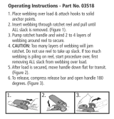
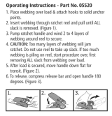
C. Rescue Cradle:
IMPORTANT: Consult competent personnel before moving injured or disabled
person. Remove all sharp objects from person being transported to avoid
tearing the cradle.
Step 1. Open cradle on floor near the escape point.
Step 2. Place the disabled person in the center of the cradle.
Step 3. Snap all three rings to the triangular D-ring on the escape belt
with the carabiner provided. See Figure 15.
Step 4. Drop the reel with the “return cable” to the ground. For cable
lengths over 250 ft (76.2m)see section 3.3 (B).
Figure 14
Cotter Pin
Knob
Pulley
Face
Plate
Figure 15
Figure 9
Figure 10
Figure 11
Figure 12
Figure 13

9
Step 5. Move disabled person in cradle to launch area. Pull on free end of rope to take up the slack. Rope must
be taught before descending. Slowly release cradle to begin descent.
Step 6. The guideline attached to the bottom of the cradle is used to steer the cradle past obstructions to the
ground.
CAUTION: Exert steady pull on guideline - never tug violently, cradle may tear. Do not pull guideline to cause cradle
angle to exceed ten degrees to vertical. To avoid damage to the guideline, never wrap around any object to control
descent speed or direction of descent. Swing injury may result if guideline breaks. Do not put sharp objects in cradle
which may rip or tear cradle.
4.0 TRAINING
4.1 It is the responsibility of the user to assure they are familiar with these instructions, and are trained in the correct
care and use of this equipment. User must also be aware of the operating characteristics, application limits, and the
consequences of improper use of this equipment.
WARNING: Training must be conducted without exposing the trainee to a fall hazard. Training should be repeated on
a periodic basis. Always use a back-up system when training.
4.2 All persons should experience the descent on the Rescumatic® Emergency Escape Device before the event of
an emergency situation which will require it’s use. Demonstrations organized at the time of installation are strongly
recommended with repeat demonstrations every six months just after the maintenance check (see section 6.0).
Initial training is advised from a low height, for example a standing height of approximately six feet above ground.
This is usually done by attaching the Rescumatic® unit to a crane or hoist hook at ground level and then raising
a person off the ground a few feet before the descent is allowed to begin.
It is highly recommended that a full body harness be used by the trainee. The Rescumatic® Emergency Escape
Device should be attached to the dorsal D-ring or the front D-ring. Attachment of the harness to the descent
device is made by using a carabiner connected to the D-ring on the harness and the metal D-ring on the end of
the Rescumatic® body support.
A backup fall arrest system (such as a self retracting lifeline) should be utilized during all training descents. A
means of rescue should be available during all training descents.
5.0 INSPECTION
5.1 MONTHLY: A formal inspection should be completed by a competent person other than the user. A formal
inspection should be completed if the system parameters are changed, such as after a system is moved,
re-rigged, anchorages moved, guide cable angle changed, etc. Extreme working conditions may require
increasing the Inspection frequency. Inspect the Rescumatic® Emergency Escape Device according to sections
5.2 and 5.3. Record inspection results in the inspection and maintenance log in section 9.0.
5.2 Inspection steps:
Step 1. Inspect device for loose fasteners and bent or damaged parts.
Step 2. Inspect cover and base plate for distortion, cracks or other damage.
Step 3. Device rope must pull out freely in both directions.
Step 4. Inspect rope for cuts, wear, breaks, or abraded cover.
IMPORTANT: After several descents the outside portion of the rope will begin to loosen up and increase in diameter.
This is a sign of wear and will potentially cause interference and binding as the rope enters and exits the descent unit.
Inspect the rope carefully and replace the rope immediately if the rope cover is loose, warn, or begins to bunch up as
the rope enters the descent unit.
Step 5. Inspect for corrosion.

10
Step 6. Inspect connecting carabiner and web body support for damage.
Step 7. Inspect rope spool for damage.
Step 8. Inspect angled guide line (if present).
Step 9. Inspect cover/enclosure.
Step 10. Inspect Rescue Cradle (if present).
5.3 If inspection reveals an unsafe condition, remove device from service and contact DBI/SALA or a authorized
service center for repair.
6.0 MAINTENANCE and STORAGE
6.1 Six Month Maintenance Check:
Step 1. Remove screw and metal cover to observe free movement of gears by passage of cable.
Step 2. Blow out any dust accumulation with air hose. DO NOT OIL!
Step 3. Check cable for wear. Worn cable must be replaced immediately. Only cable supplied by DBI/SALA
is acceptable for use with the Rescumatic® descent system.
Step 4. Evidence of chemical attack or environmental effects on the material of construction must immediately
be referred to DBI/SALA.
Step 5. Rotate internal drum. Drum should rotate freely.
Step 6. Inspect inside surface of brake drum. Check for brake lining wear evident by ridges or grooves inside
of brake drum.
Step 7. Replace metal cover and screw.
Step 8. A practice descent is strongly recommended after each maintenance check. See section 4.0.
Step 9. Return unit back to original location. Ensure that the Rescumatic® equipment is protected from the
effects of weather and environment until the next inspection. A vinyl protective cover is supplied by
DBI/SALA.
6.2 If maintenance check reveals an unsafe condition, remove from service immediately and contact DBI/SALA or
an authorized service center for repairs.
6.3 Service: Maintenance and servicing must be completed by an authorized service center. An authorization and
return number must be issued by DBI/SALA. Contact DBI/SALA for service frequencies when this equipment is
used in extreme working conditions.
6.4 Storage: The Rescumatic® Emergency Escape Device must be protected from the weather in a weather-
resistant container. The unit must also be protected from long term effects of sunlight which may cause
degradation of the belts and other synthetic materials.
Outdoors a protective box should be constructed to suit local conditions. The box should be dry, resistant to salt
spray, wind, fumes, and UV light.
Indoors for dusty locations, all permanently installed Rescumatic® units should be protected with a vinyl
protective cover furnished with each unit. This cover is not suitable for outdoor installation.
Inspect the Rescumatic® Device after extended storage.

11
7.0 SPECIFICATIONS
Rescumatic:
Hardware: High tensile alloy steel snap hook, stainless steel rivet, aluminum ferrule, plastic thimble, copper button
stop, alloy steel single pass buckle
Webbing: 1 3/4-in. (45mm) polyester strength member
Rope: 5/16-in. (8mm) braided polyester, 1/8-in. (3.2mm) diameter galvanized wire core, 7 x 19 construction.
In Canada: 3/16 in.(4.7mm) diameter galvanized wire core, 7 x 19 construction.
Capacity: 300 lbs. (136kg) (one person)
Rescumatic® Emergency Escape Device meets CSA Z259.2.3 - Class 1E.
Rescue Cradle:
Hardware: High tensile alloy steel snap hook, aluminum ferrule
Webbing: 1-3/4in. (45mm) polyester strength member
Cradle: Treated canvas with polyester web
Rope: 3 strand polypropylene
Capacity: 350 lbs. (159kg) (one person)
Snatch Block:
Hardware: Forged steel swivel tee and yokes, bronze bushing
Fits cable size: 5/16-in. to 3/8-in. diameter (8.0mm to 9.5mm diameter)
Rescumatic® Side Labels
U. S. Rescumatic Face Label
Canadian Rescumatic Face Label

12
Rescumatic® Rope System Label
Rescue Cradle ID Label
8.0 LABELING
8.1 These labels must be present and fully legible:
8.1 Continued:

13
ETADNOITCEPSNISMETINOITCEPSNI
DETON
NOITCAEVITCERROCECNANETNIAM
DEMROFREP
:yBdevorppA
:yBdevorppA
:yBdevorppA
:yBdevorppA
:yBdevorppA
:yBdevorppA
:yBdevorppA
:yBdevorppA
:yBdevorppA
:yBdevorppA
:yBdevorppA
:yBdevorppA
9.0 INSPECTION AND MAINTENANCE LOG
DATE OF MANUFACTURE: _______________________________________________________________________
MODEL NUMBER: ______________________________________________________________________________
DATE PURCHASED: ________________________________________________________________________________

14
ETADNOITCEPSNISMETINOITCEPSNI
DETON
NOITCAEVITCERROCECNANETNIAM
DEMROFREP
:yBdevorppA
:yBdevorppA
:yBdevorppA
:yBdevorppA
:yBdevorppA
:yBdevorppA
:yBdevorppA
:yBdevorppA
:yBdevorppA
:yBdevorppA
:yBdevorppA
:yBdevorppA
9.0 INSPECTION AND MAINTENANCE LOG
DATE OF MANUFACTURE: _______________________________________________________________________
MODEL NUMBER: ______________________________________________________________________________
DATE PURCHASED: ________________________________________________________________________________

15
ETADNOITCEPSNISMETINOITCEPSNI
DETON
NOITCAEVITCERROCECNANETNIAM
DEMROFREP
:yBdevorppA
:yBdevorppA
:yBdevorppA
:yBdevorppA
:yBdevorppA
:yBdevorppA
:yBdevorppA
:yBdevorppA
:yBdevorppA
:yBdevorppA
:yBdevorppA
:yBdevorppA
9.0 INSPECTION AND MAINTENANCE LOG
DATE OF MANUFACTURE: _______________________________________________________________________
MODEL NUMBER: ______________________________________________________________________________
DATE PURCHASED: ________________________________________________________________________________

I S O
9 0 0 1
Certificate No. FM 39709
Form: 5906277
Rev: G
This instruction applies to the following models:
Additional model numbers may appear on the next printing of these instructions
USA Canada
3833 SALA Way 260 Export Boulevard
Red Wing, MN 55066-5005 Mississauga, Ontario L5S 1Y9
Toll Free: 800-328-6146 Toll Free: 800-387-7484
Phone: (651) 388-8282 Phone: (905) 795-9333
Fax: (651) 388-5065 Fax: (905) 795-8777
www.capitalsafety.com www.capitalsafety.com
This manual is available for download at www.capitalsafety.com.
A CAPITALSAFETY COMPANY
3300008
3300010
3300016
3300018
3300020
3300021
3300022
3300024
3300025
3300026
3300027
3300028
3300029
3300030
3300032
3300033
3300034
3300035
3300038
3300040
3300041
3300042
3300043
3300044
3300045
3300046
3300050
3300052
3300053
3300055
3300060
3300062
3300065
3300066
3300069
3300070
3300071
3300073
3300075
3300076
3300077
3300080
3300081
3300084
3300085
3300089
3300090
3300095
3300096
3300100
3300105
3300110
3300112
3300115
3300116
3300120
3300125
3300128
3300130
3300131
3300138
3300140
3300142
3300143
3300150
3300160
3300165
3300170
3300175
3300180
3300182
3300185
3300190
3300200
3300210
3300212
3300215
3300225
3300227
3300231
3300235
3300240
3300250
3300260
3300265
3300275
3300280
3300282
3300300
3300310
3300330
3300340
3300350
3300390
3300400
3300430
3300440
3300450
3300490
3300500
3300520
3300610
3300660
3300700
3300750
3300800
3300850
3301000
3305000
3308006
3308007
3310035
3310045
3310080
3310085
3610000
3610050
3610055
3610080
3610100
3610150
3610200
3610400
3610500
/