Page is loading ...

INSTALLATION INSTRUCTIONS AND OWNER’S MANUAL
Models: 3663-372
Installation Instructions
and Owner’s Manual
IMPORTANT NOTICE!
To avoid possible injury, read the enclosed instructions carefully
before installing/operating this garage door opener. Pay close
attention to all warnings and notes. This manual MUST be attached
to the wall in close proximity to the garage door opener.
Copyright 2008 Wayne-Dalton Corp. Rev 7 7/16/2008
Part No. 320687
USE OF THIS MANUAL
WHEN INSTALLING A NEW DOOR WITH AN IDRIVE
®
:
If you just fi nished installing a new garage door along with
an idrive
®
opener, then proceed with these instructions
beginning with Step 14 on page 21. If you were referred to
these instructions as part of a new door installation, then
proceed with these instructions beginning with Step 1 on
page 7.
for TORQUEMASTER
®
/
TORQUEMASTER
®
PLUS
PHOTOELECTRIC EYES ARE NOT REQUIRED ON
WAYNE-DALTON SERIES 9000 AND MODEL 5120
AND 5140 DOORS. ALL OTHER DOORS, WHICH DO
NOT HAVE PINCH-RESISTANT SECTION JOINTS,
REQUIRE PHOTOELECTRIC EYES TO PREVENT
POSSIBLE SEVERE OR FATAL INJURY.
WARNING
GARAGE DOORS & OPENERS

HOW idrive
®
WORKS
1
3
2
Lift cables raise door
from bottom.
MOUNTS ON THE WALL INSTEAD OF CLUTTERING THE CEILING
1
2
idrive
®
mounts to the
counterbalance above door.
Security arm manually locks
closed door.
3

T
o
O
p
e
r
a
t
e
D
o
o
r
Press
Here
9 0
7 8
5 6
3 4
1 2
Package Contents
Key chain/Visor
Transmitter (2)
Opener
Deluxe Multi-function
Wireless Wall Station
Security Light with
Diffuser
Disconnect Handle
Disconnect
Handle Bracket
“S” Hook
1/4” x 1-1/2" Hex Head
Lag Screws (4)
#6 x 7/8" Phillips Pan
Head Screws (4)
Disconnect Cable
1/4” x 2" Hex Head Lag
Screws (2)
Owner’s Manual
Emergency
Disconnect Label
Installation DVD
Entrapment Label
5 Button Wireless
Keyless Entry
#6-20 x 1/2" Phillips
Pan Head Screw (1)
Lock Arm Assembly
Cable Clips (4)
#6-32 x 3/4" Phillips Pan Head
Screw (1)
(For Light Fixture)
5mm x .8mm x 12mm
Phillips Pan Head Screw (1)
(For Lock Arm)
Mounting Bracket
I
Please Do Not Return This Product To The Store. Call Us Directly! Our Trained Technicians Will Answer Your Questions and/or Ship Any Parts You May Need.
You can reach us Toll Free at 1-888-827-3667 for Consumer Assistance or online at www.wayne-dalton.com
Jumper
(Optional for Safety Sensors)

II
Please Do Not Return This Product To The Store. Call Us Directly! Our Trained Technicians Will Answer Your Questions and/or Ship Any Parts You May Need.
You can reach us Toll Free at 1-888-827-3667 for Consumer Assistance or online at www.wayne-dalton.com
PRE-INSTALLATION INSPECTION OF YOUR GARAGE DOOR
PRIOR TO TORQUEMASTER
®
IDRIVE
®
INSTALLATION
Congratulations, you have just purchased one of the world’s safest garage door openers! By
design, this opener will detect obstructions and reverse rather than force the door through
obstructions.
To ensure your new idrive
®
opener works as intended, your garage door must be
installed and balanced properly.
WHEN INSTALLING A NEW DOOR WITH AN IDRIVE
®
:
If you just nished installing a new garage door along with an idrive
®
opener, then proceed with
these instructions beginning with Step 14 on page 21. If you were referred to these instructions
as part of a new door installation, then proceed with these instructions beginning with Step 1
on page 7.
WHEN INSTALLING AN IDRIVE
®
ON AN EXISTING DOOR WITH TORQUEMASTER
®
OR
TORQUEMASTER
®
PLUS:
Before installing the idrive
®
opener, open and close you door manually to ensure that it
operates smoothly from top to bottom. A properly balanced door should not take a lot of effort
to open or close by hand. The door should stay in the open and in the closed position without
drifting down or creeping up. If a door opens fast going up, the door may need spring tension
reduced. If the door drops fast going down, the door may need spring tension increased.
If the operation of the door does not meet these criteria, you need to adjust the spring balance
per your door’s Installation Instructions and Owner’s Manual or call a professional installer to
make adjustments before installing idrive
®
.
If the door operates properly, check and record your Torquemaster
®
counterbalance spring
settings (for Torquemaster Plus spring settings, see warning tag(s) attached to the end
brackets or refer to your door Installation Instructions and Owner’s manual). Then proceed
with unwinding of the spring(s) for installation of your idrive
®
, carefully following the
instructions in the appropriate STEP R1 of your idrive
®
Installation Instructions and Owner’s
Manual. After the idrive
®
is installed on the Torquemaster
®
tube, rewind the Torquemaster
®
or
Torquemaster
®
Plus to the previously recorded settings.
Instruction manuals are available for download on www.wayne-dalton.com. Use the web site
to also nd the location of your nearest professional dealer.
Check out the new idrive
®
installation video at www.wayne-dalton.com
Idrive
®
for Torquemaster
®
http://www.wayne-dalton.com/idrive_TorqueMaster.asp
Look for this symbol.
®

Torque Tube
1” Clearance for Motor
Top of
Door
End Bracket
Mounting Surface
Electrical outlet on the
wall is for opener
Electrical outlet on
the ceiling is for
light/opener
Pre-Installation
Inspection
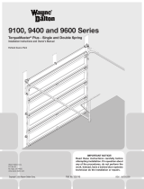
A. You must have a Wayne-Dalton Torquemaster
®
or Torquemaster
®
Plus counterbalance system to install this opener (see A above).
B. The motor requires 1" of clearance above the top of the end
bracket for Torquemaster and 1-1/4” of clearance above the top
of the end bracket for Torquemaster plus.
C. Two electrical outlets are recommended for the idrive
®
installation. One of these outlets needs to be located less than 6'
from the opener. The second outlet, for the light, can be located
at a position of your choice.
If, in the event that an electrical outlet is not located within 6' of
the opener, contact a local electrician for further options. As a
convenience, an electrical outlet is provided on the light fixture.
The 6’ opener cord can be used with this outlet.
D. Your door must not exceed 8' in height.
E. The idrive
®
opener will only work on sectional doors. Do not
install on one-piece doors.
F. Your garage door must be properly balanced (door must not be
heavy to lift, nor lift by itself).
G. Horizontal tracks should be raised 1" above level at rear of Track.
H. We do not recommend installing the idrive
®
opener on
Model 9700 door widths of 16’ - 18’.
I. Maximum door weight (without spring tension) must not
exceed 304 lb.
CAUTION: DO NOT INSTALL THIS OPENER ON YOUR DOOR UNLESS THE FOLLOWING REQUIREMENTS ARE MET.
USE THE ILLUSTRATION ABOVE AS A VISUAL AID.
III
Please Do Not Return This Product To The Store. Call Us Directly! Our Trained Technicians Will Answer Your Questions and/or Ship Any Parts You May Need.
You can reach us Toll Free at 1-888-827-3667 for Consumer Assistance or online at www.wayne-dalton.com
PRE-INSTALLATION INSPECTION
CAUTION! Do not install this opener on your door unless
the following requirements are met.
C
B
A
Torquemaster
®
Plus Torquemaster
®
PHOTOELECTRIC EYES ARE NOT REQUIRED ON WAYNE-DALTON
SERIES 9000 AND MODEL 5120 AND 5140 DOORS. ALL OTHER
DOORS, WHICH DO NOT HAVE PINCH-RESISTANT SECTION JOINTS, REQUIRE PHOTOELECTRIC
EYES TO PREVENT POSSIBLE SEVERE OR FATAL INJURY.
WARNING

Safety Glasses
Phillips Head
Screwdriver
Step Ladder
Ratchet Wrench
7/16” Wrench 5/64” Drill Bit
3/16” Drill Bit
1/8” Drill Bit7/16” Socket
Flat Tip
Screwdriver
Needle Nose Pliers
Level7/16” Socket Driver
Pliers/Wire
Cutters
3/32” Drill Bit
Tape Measure
Pencil
Power Drill
CAUTION TO REDUCE THE RISK OF INJURY, USE THIS OPENER ONLY WITH THE FOLLOWING DOOR MODELS:
System Requirements
Locking Pliers
WAYNE-DALTON
DOOR MODEL
WAYNE-DALTON
SPRING SYSTEM
TRACK (RADIUS)
PHOTOELECTRIC
SAFETY SENSORS
LOW HEAD
ROOM KIT
9000 SERIES,
5120 & 5140
Torquemaster
®
Torquemaster
®
Plus
10",12",14",15" Not Required Not Required
9000 SERIES,
5120 & 5140
Torquemaster
®
Torquemaster
®
Plus
6" Low Head Room Not Required
P/N 302883
Required
Door Models below require the use of photo eyes.
8000 SERIES or
other doors
Torquemaster
®
Torquemaster
®
Plus
10",12",14",15"
P/N’s 252118 or
301674 Required
Not Required
8000 SERIES or
other doors
Torquemaster
®
Torquemaster
®
Plus
6" Low Head Room
P/N’s 252118 or
301674 Required
P/N 302883
Required
IV
Please Do Not Return This Product To The Store. Call Us Directly! Our Trained Technicians Will Answer Your Questions and/or Ship Any Parts You May Need.
You can reach us Toll Free at 1-888-827-3667 for Consumer Assistance or online at www.wayne-dalton.com
Vice Clamps
Tools Needed

Table of Contents
Package Contents ............................................................................... I.
Pre-Installation Inspection ................................................................... II, III.
Tools Needed ...................................................................................... IV.
Important Safety Instructions .............................................................. V.
Retro-Fit Installations .......................................................................... 1-6.
idrive
®
for Torquemaster
®
Installation ................................................. 7-21.
Pre-Operation ...................................................................................... 21-32.
Operation ............................................................................................ 33-38.
Maintenance ....................................................................................... 38.
Power Connection-Permanent Wiring Option........................................39.
Programming Wireless Wall Station(s) or Transmitter(s) to Opener ...... 40.
Troubleshooting ................................................................................... 41-42.
Warranty ............................................................................................. 43.
Customer Service Number .................................................................. 44.
Drill Template.......................................................................................44.
INCORRECT INSTALLATION CAN
LEAD TO SEVERE OR FATAL
INJURY. FOLLOW THESE
INSTRUCTIONS CAREFULLY.
IMPORTANT SAFETY
INSTRUCTIONS
1. READ AND FOLLOW ALL INSTALLATION INSTRUCTIONS.
2. Do not connect the opener to electrical power until instructed
to do so.
3. Install the entrapment warning label next to the wall station in
a prominent location. Install the emergency disconnect label
next to the emergency disconnect.
4. Remove all ropes and remove, or make inoperative in the unlocked
position, all locks connected to the garage door before installing the
opener.
5. Do not wear rings, watches or loose clothing when installing
or servicing a garage door system.
6. It is important that you install all the components supplied with the
idrive
®
opener, i.e., wall stations, safety sensors, etc. Use
of parts not supplied by Wayne-Dalton Corp. may cause the opener to
malfunction and create unsafe conditions.
7. Wear safety glasses for eye protection when installing or servicing the
opener or door.
8. Install opener on a properly balanced and operating garage
door. Have a qualified service person make adjustments/repairs
to cables, spring assemblies, and other hardware before
installing the opener. An improperly balanced door could
cause severe injury.
9. Where possible, install the opener seven feet or more above the floor.
Mount the emergency disconnect six feet above the floor.
10. Locate the wall station: (a) within sight of door, (b) at a minimum
height of five feet, so small children cannot reach it, and (c) away from
all moving parts of the door.
11. After installing the opener, the door must reverse when it contacts a 1-
1/2” high object (or 2 x 4 board laid flat) on the floor.
12. Installation and wiring must comply with local building and electrical
codes. Connect the power cord to a properly grounded outlet. Do not
remove the ground pin from power cord.
AFTER INSTALLATION IS COMPLETE, FASTEN
THIS MANUAL NEAR GARAGE DOOR.
PERFORM MONTHLY OBSTRUCTION TEST
AND MAINTENANCE AS RECOMMENDED. SEE
PAGES
31, 32 AND 38.
WARNING
V
Please Do Not Return This Product To The Store. Call Us Directly! Our Trained Technicians Will Answer Your Questions and/or Ship Any Parts You May Need.
You can reach us Toll Free at 1-888-827-3667 for Consumer Assistance or online at www.wayne-dalton.com
Defi nition of key words used in this manual:
INDICATES A POTENTIALLY HAZARDOUS SITUATION
WHICH, IF NOT AVOIDED, COULD RESULT IN SEVERE
OR FATAL INJURY.
CAUTION: PROPERTY DAMAGE OR INJURY CAN RESULT FROM
FAILURE TO FOLLOW INSTRUCTIONS.
IMPORTANT: REQUIRED STEP FOR SAFE AND PROPER DOOR
OPERATION.
NOTE: Information assuring proper installation of the door.
WARNING

1
Please Do Not Return This Product To The Store. Call Us Directly! Our Trained Technicians Will Answer Your Questions and/or Ship Any Parts You May Need.
You can reach us Toll Free at 1-888-827-3667 for Consumer Assistance or online at www.wayne-dalton.com
R2
Spring Tension Removal
Counterbalance spring tension must be
relieved before removing any hardware.
A POWERFUL SPRING RELEASING ITS
ENERGY SUDDENLY CAN CAUSE SEVERE
INJURY.
Starting with the right hand side, ensure
pawl knob is in upper position. Place a
ratchet with a 5/8” socket on the winding
shaft.
NOTE: A 3” extension is also recommended
for added clearance from the horizontal
angle.
To remove spring tension, ensure the ratchet
and socket is set so that it will add tension
(counter clockwise) on the right hand side
and (clockwise) on the left hand side. Rotate
ratchet to relieve pressure between the pawl
and the ratchet wheel. Push in on the pawl
to allow the ratchet wheel teeth to pass by.
NOTE: In the event of a broken spring, it
might not be necessary to unwind spring(s).
IMPORTANT! BE PREPARED TO HOLD THE
FULL TENSION OF THE SPRING.
Gently let the ratchet rotate upward, while
watching the number of teeth on the ratchet
wheel pass by the pawl. Remove 3/10 of a
turn (watch the 3 teeth of the ratchet wheel
pass the pawl). Release the pawl to allow it
to engage with the ratchet wheel. Repeat
this process until all spring tension has been
removed from spring(s). Cables should be
loose and the torque tube should be free to
rotate in either direction.
IMPORTANT! SPRING(S) ARE FULLY
UNWOUND WHEN COUNTERBALANCE
CABLES HAVE NO TENSION.
IMPORTANT! DO NOT USE AN IMPACT GUN
TO UNWIND THE SPRINGS.
Tools Needed:
Ratchet Wrench
5/8” Socket
3” Extension
Gloves
Step Ladder
INSTALLATION NOTICE: If installing the idrive
®
opener on a door currently installed with Torquemaster
®
Plus counterbalance system,
start the installation with Step: R1 below. For Torquemaster
®
counterbalance system, start the installation with Step R1 on page 3.
Pawl Knob In Upper Position
END BRACKET
Pawl Knob In Lower Position
END BRACKET
R1
Retro-Fit Installation
Drum Wrap & End Bracket
Removal
IMPORTANT! RIGHT AND LEFT HAND IS
ALWAYS DETERMINED FROM INSIDE THE
BUILDING LOOKING OUT.
NOTE: Warning tag removed for illustration
clarity.
Starting on the right hand side, unlock the
drum wraps from the cable drums. Un-snap
hinged latch. PULL COUNTERBALANCE
CABLE SLIGHTLY OUTWARD FROM THE
JAMB to allow hinged latch to pass to the left
of the cable. Pry radially outward with a small
screwdriver on the three tabs (one at a time)
while maintaining pressure on drum wrap in
direction shown to remove. Repeat drum wrap
removal for left side.
Tools Needed:
Step Ladder
Flat Blade
Screwdriver
Retro-Fit TorqueMaster
®
Plus
WARNING
Ratchet
RIGHT HAND SIDE
LEFT HAND SIDE
Marks
3” Extension
Pawl
Marks
3” Extension
Ratchet
TORQUEMASTER
®
PLUS END BRACKET
(Right hand shown, left hand bracket symmetrically opposite)
PAWL KNOB
IN UPPER POSITION
PAWL KNOB
IN LOWER POSITION
Pawl
Ratchet Wheel
PAWL
RATCHET PAWL
RATCHET WHEEL
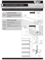
Pushing in on Pawl Causes
Ratchet Pawl to move away
from Ratchet Wheel, allowing
wheel teeth to pass by.
Drum Wrap
Drum
Before
After
Hinged Latch
Counterbalance
Cable
Tab x 3
Hinged Latch
Counterbalance
Cable

2
Please Do Not Return This Product To The Store. Call Us Directly! Our Trained Technicians Will Answer Your Questions and/or Ship Any Parts You May Need.
You can reach us Toll Free at 1-888-827-3667 for Consumer Assistance or online at www.wayne-dalton.com
Winding Shaft
Cable
Drum
Groove
Round Notch
Flagangle
Splines
Drum
Wrap
R3
End Bracket Removal
To remove end brackets, start with the right
hand end bracket and remove (1) 5/16”-18
x 3/4” carriage bolt, 3/4” washer and hex
nut; then the 5/16” x 1-5/8” hex head lag
screw holding the bracket to the jamb.
Repeat for left hand end bracket.
CAUTION: THE WINDING SHAFT MAY
ROTATE WHEN REMOVING THE END
BRACKET AND GEAR.
Tools Needed:
Power Drill
7/16” Socket
Driver
1/2” Wrench
Step Ladder
Center Bracket & Cable Drum
Removal
To remove the cable drum/center bracket,
follow the steps below:
a. Remove the two 1/4" lag screws from
the center bracket. slide center bracket
to the right side of the torque tube.
Lift the right side of the torque tube up
and slide the cable drum and center
bracket off the end of the torque tube.
discard the center bracket.
b. Drape the cable drum over the flagangle
by the counterbalance cable and re-align
the groove in the winding shaft with the
round notch in the flagangle.
Once aligned, lower the winding shaft
and torque tube onto the flagangle.
Repeat cable drum removal for left side.
After completing this step, continue with
Step R5 on page 5.
R4
a
b
1/4”
Lag Screws
Center
Bracket
Torque
Tube
Tools Needed:
Power Drill
7/16" Socket
Driver
Step Ladder
Cable Drum
No space between Ratchet
Pawl and Cable Drum
indicates engagement
Cable Drum
Ratc
het Pawl
ENGAGED SIDE VIEW
No space between
Ratchet Pawl and
Cable Drum
ENGAGED U
NDE
RNE
ATH V IEW
Space between Ratchet Pawl
and Cable Drum
non-in
dicates engagement
Cable Drum
Ratchet Pawl
DISENGAGED SIDE
VIEW
No space between
Ratchet Pawl and
DISENGAGED U
NDER
NE
A
T
H V
IEW
UPPER POSITION
LOWER POSITION
UPP
ERPO
Rat
chet
R
atchet Pawl in Upper Position
Use these Illustration, in conjunction with the Instructions on the other side of
this label.
WARNING
WA
RNI
NG
Rachet Bracket is under
Rachet
Bra
cke
t
i
s
un
de
r
EXTREME SPRING
EXTR
EME SPR
IN
G
TENSION
TENSION
.
To avoid possible severe or
T
o avoi
d poss
i
ble sever
e or
fatal injury,
fatal
i
njur
y
,
DO NOT
D
O
N
O
T
remove
r
em
ove
fasteners from ratchet bracket
f
astene
r
s
f
r
om ratchet br
ack
et
until spring(s) are fully
un
ti
l
spr
i
ng
(
s) ar
e full
y
wnwound.
wnwound
.
To safely unwind spring(s)
To safely
un
w
i
nd spr
i
ng
(s)
read
r
ead
and follow the directions in the
and f
oll
ow
t
he
dir
ecti
on
s in
the
installation instructions/owners
i
nstal
l
ation
i
nstru
ct
i
on
s/ow
ners
manual.
m
an
ual
.
DO NOT REMOVE THIS TAG.
D
O
N
OT REMOV
E TH
I
S TA
G
.
5/16” X 1-5/8”
Hex Head Lag
End Bracket
(Right Hand)
5/16”-18 Hex Nut
5/16” - 18 X 3/4”
Carriage Bolt
RETRO-FIT TORQUEMASTER
®
PLUS
3/4” WASHER

3
Please Do Not Return This Product To The Store. Call Us Directly! Our Trained Technicians Will Answer Your Questions and/or Ship Any Parts You May Need.
You can reach us Toll Free at 1-888-827-3667 for Consumer Assistance or online at www.wayne-dalton.com
R1
Retro-Fit Installation
Spring Tension Removal
Counterbalance spring tension must be
relieved before removing any hardware.
A POWERFUL SPRING RELEASING ITS
ENERGY SUDDENLY CAN CAUSE SEVERE,
EVEN FATAL INJURY.
NOTE: Warning tag removed for illustration
clarity.
Place door in the fully closed position and
remove drum wraps from cable drums (if
installed).
Using a 7/16" wrench, loosen lock nut on
the back of the end bracket. Using a power
drill (high torque/gear reduced to 1300 RPM
preferred), with a 7/16" socket driver,
unwind the right hand winding bolt counter
clockwise until the counter cover shows “0”
(zero). If the door has two springs, repeat
this process for the left hand side.
NOTE: A door with only one spring will not
have a counter assembly on the left hand
side.
NOTE: Spring(s) is/are fully unwound when
counterbalance cables have no tension.
CAUTION: DO NOT USE AN IMPACT GUN
TO UNWIND THE SPRINGS!
NOTE: It is recommended that cable drums
and end bracket assemblies get updated to
current designs for optimal performance.
current end brackets are made of metal
instead of plastic, and counter cover and
worm gears are made of grey plastic, instead
of black and white plastic. If new parts are
required, contact Wayne-Dalton customer
service.
Tools Needed:
Flat Tip
Screwdriver
Step Ladder
R2
Right Hand Counter Removal
IMPORTANT! RIGHT AND LEFT HAND IS
ALWAYS DETERMINED FROM INSIDE THE
GARAGE LOOKING OUT.
Remove the counter cover. Slide a flat tip
screwdriver between the end bracket and
the counter gear.
Gently pull the counter gear away from the
end bracket. If the door has two springs,
repeat this process for the opposite side.
7/16”
Wrench
Lock Nut
Power
Drill
Counter
Balance
Cable
Drum
Wrap
End Brackets
(Metal)
Counter
Cover
Worm
Gear
Counter
Gear
Flat Tip
Screwdriver
End Brackets
(Metal)
Counter
Cover
WARNING
Winding
Bolt
Winding
Bolt
Tools Needed:
7/16" Wrench
Power Drill
7/16"
Socket Driver
Step Ladder
Cable
Drum
7/16”
Socket Driver
Retro-Fit TorqueMaster
®

4
Please Do Not Return This Product To The Store. Call Us Directly! Our Trained Technicians Will Answer Your Questions and/or Ship Any Parts You May Need.
You can reach us Toll Free at 1-888-827-3667 for Consumer Assistance or online at www.wayne-dalton.com
R3
End Bracket Removal
To remove the end brackets, follow the
steps below starting with the right hand
end bracket first:
a. Remove the upper lag screw from the
end bracket.
b. Attach a pair of locking pliers to the
upper portion of the end bracket and
hold the end bracket steady while
removing the lower lag screw.
If present, remove and save the #10
phillips head screw.
c. Holding the end bracket with the locking
pliers, carefully pry the end bracket from
the cable drum with a flat tip
screwdriver.
Repeat for left hand end bracket.
CAUTION: THE WINDING SHAFT MAY
ROTATE WHEN REMOVING THE END
BRACKET AND GEAR.
Center Bracket & Cable Drum
Removal
To remove the cable drum/center bracket,
follow the steps below:
a. Remove the two 1/4" lag screws from
the center bracket. Slide center bracket
to the right side of the torque tube.
Lift the right side of the torque tube up
and slide the cable drum and center
bracket off the end of the torque tube.
Discard the center bracket.
b. Drape the cable drum over the flagangle
by the counterbalance cable and re-align
the groove in the winding shaft with the
round notch in the flagangle.
Once aligned, lower the winding shaft
and torque tube onto the flagangle.
Repeat cable drum removal for left side.
After completing this step, continue with
Step R5 on page 5.
R4
Upper
Lag Screw
Lower
Lag Screw
#10 Phillips
Head
Screw
Flat Tip
Screwdriver
a b
c
a
b
1/4”
Lag Screws
Center
Bracket
Torque
Tube
Winding
Shaft
Round Notch
in Flagangle
Cable
Drum
Cable
Drum
RETRO-FIT TORQUEMASTER
®
Tools Needed:
Locking Pliers
Phillips Head
Screwdriver
Flat Tip
Screwdriver
Power Drill
7/16” Socket
Driver
Step Ladder
Tools Needed:
Power Drill
7/16" Socket
Driver
Step Ladder
End
Bracket
Locking
Pliers
Flagangle
Counterbalance
Cable

5
Please Do Not Return This Product To The Store. Call Us Directly! Our Trained Technicians Will Answer Your Questions and/or Ship Any Parts You May Need.
You can reach us Toll Free at 1-888-827-3667 for Consumer Assistance or online at www.wayne-dalton.com
If installing an idrive
®
opener on an installed
9100 door, the top bracket and roller
location will have to be adjusted for the
opener to work properly.
Loosen the (2) 1/4”-20 nuts from the top
bracket slide.
Remove the (4) 1/4”-14 x 5/8" self-tapping
screws from the top bracket.
Raise the top bracket to align the bottom
slots with the second set of holes in the
end cap.
Re-attach top bracket to the end cap with
the (4) 1/4”-14 x 5/8" self-tapping screws.
Re-align the top roller in the horizontal track
by moving the top bracket slide out to force
the door section against the weather seal.
Tighten (2) 1/4”-20 Nuts.
Repeat for the opposite side.
NOTE: The 9100 doors have a painted steel face, foam insulation and
white paper backing. If your door does not match this description you may
skip this step.
CAUTION: TO AVOID THE TOP PANEL FROM FALLING, COMPLETE RE-
INSTALLATION ON ONE SIDE BEFORE BEGINNING THE OTHER.
R5
9100 Top Bracket
Re-Install (If Necessary)
NOTE: The door must be in the fully closed
position.
If installing an idrive
®
opener on an
8000/8100/8200 door, the top roller location
and track height will have to be modified for
the opener to work properly. Perform the
following steps:
NOTE: The bottom edge of the track needs to
be spaced 1” above the floor. If the track is
already spaced off the floor 1”, skip this step.
Fasten a nail in the door jamb, between the
door and the track at the ends of each
section. Bend the nail over each section to
hold them in place.
Remove the lag screws from the flagangle and
each jamb bracket. Using a 7/16" socket
driver, loosen the flange nut on the Top
bracket slide. Place a mark 1" up from one of
the tops of one of the jamb brackets. Raise
the track up and align the jamb bracket with
this line. With the track relocated, re-attach
the flagangle, end bracket, and jamb brackets
to the header and/or door jamb. Make certain
to maintain spacing between edge of door and
vertical track.
NOTE: Pilot drill all lag screw locations.
8000/8100/8200 Track
Vertical Track Height Adjustment
(If Required)
a
b
Top
Bracket
Slide
1/4” - 20
Carriage Bolts
and Nuts
1/4” - 14 x 5/8”
Self-Tapping
Screws
Top
Roller
Horizontal
Track
Top
Bracket
Remove
Lag Screws
Jamb
Bracket
Flagangle
Nail
Nail
Nail
Nail
Nail Placement
End Cap
Track
Track
Nail bent
over door
section
Tools Needed:
Power Drill
7/16" Socket
Driver
Step Ladder
Tools Needed:
Power Drill
7/16" Socket
Drive
Pencil
Tape Measure
Step Ladder
Flange Nut
Top Bracket Slide
(Door Section)
R6

6
Please Do Not Return This Product To The Store. Call Us Directly! Our Trained Technicians Will Answer Your Questions and/or Ship Any Parts You May Need.
You can reach us Toll Free at 1-888-827-3667 for Consumer Assistance or online at www.wayne-dalton.com
1"
FAILURE TO RE-ATTACH HORIZONTAL
TRACKS TO THE SUPPORT BEFORE
OPENING DOOR CAN CAUSE DOOR
TO FALL FROM OVERHEAD POSITION,
POSSIBLY CAUSING SEVERE OR FATAL
INJURY.
NOTE:
Door must be in the fully closed
position.
If the vertical track was raised then the
horizontal track will need to be adjusted.
Remove bolt securing back of horizontal
track to the perforated angle and reposition
horizontal track UP 1” (25mm) from it’s
original position.
Re-attach the horizontal track to the
perforated angle with the same
bolt and nut.
Assemble bolt and nut from the direction
shown so bolt will extend inside of track.
8000/8100/8200 Track
Horizontal Track Height
Adjustment (If Required)
Remove the (3) self-tapping screws from
the top bracket.
Align the top hole of the top bracket with
the #2 hole in the end cap and re-attach the
top bracket to the end cap with the same
three self-tapping screws. It may be
necessary to relocate the top strut (if
installed) to correctly place the top bracket
in its new location.
Re-align the top roller in the track by
moving top bracket slide out until door
section is straight up and down. Tighten the
flange nut.
Repeat for opposite side.
8000/8100/8200 Track
Top Roller Adjustment
(If Necessary)
Perforated
Angles
Top
Strut
Self-tapping
Screws
#2 Hole
Top
Bracket
End Cap
#2 Hole with
Self-tapping
Screw
Self-tapping
Screws
Top
Strut
End Cap
Tools Needed:
Level
1/2” Wrench
Step Ladder
Tools Needed:
Power Drill
7/16" Socket
Driver
Step Ladder
Flange Nut
Door Section
Top Roller
Horizontal
Track
Bolt
Nut
Top Bracket
Slide
WARNING
RETRO-FIT INSTALLATIONS
R7
R8

7
Please Do Not Return This Product To The Store. Call Us Directly! Our Trained Technicians Will Answer Your Questions and/or Ship Any Parts You May Need.
You can reach us Toll Free at 1-888-827-3667 for Consumer Assistance or online at www.wayne-dalton.com
IMPORTANT! RIGHT AND LEFT HAND IS
ALWAYS DETERMINED FROM INSIDE THE
GARAGE LOOKING OUT.
NOTE: Older versions of the torque tube
have a label applied on the right side that
the opener will not slide over. Check the
location of the label on the torque tube. If
your torque tube has the label located on
the right side, document the information on
the label, then remove it completely using
an adhesive remover or mineral spirits. If
your torque tube has the label located on
the left side, proceed with the following
instructions.
Lay the torque tube on the floor (inside
garage) in front of the door with the labeled
end to the left.
Look into the opener’s left side to ensure
the left hand bearing and the internal (black)
sleeve are aligned with the torque tube
profile.
IMPORTANT! HOLD OPENER BY THE MAIN
BODY. DO NOT HOLD BY THE MOTOR.
Once aligned, slide the opener onto the
right hand end of the torque tube. As the
right end of the torque tube enters the
internal (black) sleeve, rotate the opener
back and forth slightly to help aid alignment.
Continue sliding the opener onto the torque
tube until the torque tube exits the opener
right hand bearing.
NOTE: Do not force the opener onto the
torque tube if misalignment occurs.
Continue sliding the opener to the center
of the torque tube.
Plug the motor power cord into the opener.
After completing this step, continue with
Step 2 on page 8 for Torquemaster
®
Plus;
Step 2 on page 10 for Torquemaster
®
.
Tools Needed:
None
Idrive
®
for Torquemaster
®
Installation
Assembling Opener
Left Hand Side
Torque Tube and
Bearing profiles
aligned
Align Torque Tube profile
with cam shaped profile
Plug-in Motor
Power Cord
Motor
1
Sleeve has cam
shaped pattern
Right Hand End
of Torque Tube cam
shaped
Right Hand End of
Torque Tube coming
out of right hand side
of idrive.

8
Please Do Not Return This Product To The Store. Call Us Directly! Our Trained Technicians Will Answer Your Questions and/or Ship Any Parts You May Need.
You can reach us Toll Free at 1-888-827-3667 for Consumer Assistance or online at www.wayne-dalton.com
NOTE: If you have a Torquemaster
®
counterbalance, skip this step and continue
with Step 2 on page 10. If you have a
Torquemaster
®
Plus counterbalance system,
complete Steps 2-3 on pages 8 and 9.
IMPORTANT! RIGHT AND LEFT HAND IS
ALWAYS DETERMINED FROM INSIDE THE
GARAGE LOOKING OUT.
Shake the TorqueMaster
®
spring tube
assembly gently to extend the winding shafts
out about 5" on each side. For single spring
applications, there will be no left hand spring
in the TorqueMaster
®
spring tube assembly.
Lift the TorqueMaster
®
spring tube assembly
and rest it on the top of the flagangles.
NOTE: Cable drums are marked right and
left hand. Cable drums and TorqueMaster
®
spring tube assembly are cam shaped to fit
together only one way.
Pre-wrap the Torquemaster
®
Plus cable
drum with the counter balance cable 1-1/2
wraps (see illustrations).
To install the cable drum, slide the correct
cable drum over the winding shaft until the
cable drum seats against the TorqueMaster
®
spring tube assembly.
The winding shaft must extend past the
cable drum far enough to expose the splines
and the groove. Align the winding shaft
groove with the round notch in the flagangle.
For double spring applications, repeat for
opposite side.
For single spring applications, insert
the loose winding shaft into the left hand
cable drum prior to sliding the cable drum
over the TorqueMaster
®
spring tube
assembly.
NOTE: On single spring applications, take
care in handling the loose winding shaft (left
side) so that it does not slide back into the
TorqueMaster
®
spring tube assembly.
Winding Shaft
Cable
Drum
Groove
Round Notch
Flagangle
Splines
Counterbalance Cable
Cable Drum
Winding Shaft
Splines
Groove
2
Cable Drums
Loose Winding Shaft
Tools Needed:
Tape Measure
Step Ladder
2
Right Drum
1-1/2 Wrap Shown
Counterbalance Cable
Drums come with drum wraps pre-installed
on them.
TorqueMaster
®
Plus Installation
IDRIVE
®
FOR TORQUEMASTER
®
INSTALLATION
5”
TorqueMaster
®
Spring Tube
Assembly (Cam Peak Straight Up)
(Right hand cable drum shown, left hand cable drum is
symmetrically opposite)
Cam Peak
Straight Up
Cam Peak
Straight Up

9
Please Do Not Return This Product To The Store. Call Us Directly! Our Trained Technicians Will Answer Your Questions and/or Ship Any Parts You May Need.
You can reach us Toll Free at 1-888-827-3667 for Consumer Assistance or online at www.wayne-dalton.com
Cable Drum
No space betwe
e
Pawl and Ca
b
indicates eng
a
C
a
Ratchet Pawl
EN
GA
GED
SID
E
V
IE
W
No space between
Ratchet Pawl and
Cable Drum
ENGAGED U
NDER
NE
A
TH V
I
E
W
Space betwee
n
R
and Cable
non-indicates e
Ratchet Pawl
DISENGAGED SIDE VIEW
No space between
Ratchet Pawl and
DISENGAGED U
NDE
R
NE
A
T
H V
IEW
UPPER POSITION
LOWER POSITION
L
UPPER POSITION SIDE VIEW
Ratchet Paw
l in Lower
P
Ratchet Pawl in Upper Position
Use these Illustration, in conjunction with the Instructions on the o
t
this label.
WARNING
WARNING
Rachet Bracket is under
Rach
e
t
B
r
a
c
ke
t
is un
d
e
r
EXTREME SPRING
EX
TR
E
ME
SP
RING
TENSION
TE
NS
IO
N
.
To avoid possible severe or
To avo
i
d
p
o
ss
i
ble se
ve
r
e
o
r
fatal injury,
fa
tal
inju
r
y,
DO NOT
DO
N
O
T
remove
re
mo
ve
fasteners from ratchet bracket
fa
sten
er
s fr
o
m ratch
e
t
b
r
a
cket
until spring(s) are fully
u
n
til
s
pr
i
ng(
s) are
f
u
l
ly
wnwound.
w
n
wo
u
n
d
.
To safely unwind spring(s)
To
sa
f
e
ly
un
wi
n
d
s
pri
n
g
(
s
)
read
r
e
a
d
and follow the directions in the
an
d fo
l
l
o
w th
e
d
i
r
e
ction
s in
th
e
installation instructions/owners
in
sta
ll
a
tion
instru
ction
s
/o
wne
r
s
manual.
ma
n
u
a
l
.
DO NOT REMOVE THIS TAG.
DO
N
OT
R
EM
O
V
E
THIS
TAG
.
Cable
Dru
m
N
o
s
pa
c
e
b
e
t
ween
R
a
tche
t
Pawl and
Cable
Dru
m
ind
i
cates
engagement
C
a
ble Drum
Ra
tc
het Pa
wl
EN
G
AGED SIDE VIEW
No space between
Ratchet
P
awl and
Cab
l
e Drum
ENGAGED U
NDERNE
A
T
H
V
I
EW
Space
b
e
t
ween R
a
tc
h
e
t
Paw
l
and C
ab
le
Dru
m
non-
i
ndicate
s
engagement
Ca
b
le
D
r
um
Ra
tch
e
t Pawl
DISEN
G
AGED SIDE VIEW
No sp
a
ce
b
etw
e
en
R
atch
e
t
Paw
l a
n
d
DISENGAGED U
NDE
R
N
E
A
T
H
V
IEW
U
P
P
ER
P
O
S
I
TION
L
O
W
ER
PO
S
ITI
O
N
LO
W
ER
P
O
SI
TI
O
N S
I
DE
V
UPPER
P
OSITION SIDE VIEW
Rat
c
het Pa
w
l in Lower
Position
Ra
t
chet Pawl in U
p
per Posi
t
ion
Use these Illus
tration, in conjunction with the Instructions on the other side of
this label.
WARNING
WARNING
Rachet Bracket is under
Ra
c
h
et
B
r
a
c
k
e
t
is
u
n
d
e
r
EXTREME SPRING
E
X
T
R
E
M
E
S
P
R
I
N
G
TENSION
TE
N
S
IO
N
.
To avoid possible severe or
To
av
o
i
d
p
os
s
ib
l
e
s
e
v
e
r
e
o
r
fatal injury,
fa
t
a
l
in
j
u
r
y,
DO NOT
DO
N
O
T
remove
r
e
mo
v
e
fasteners from ratchet bracket
f
a
s
t
e
n
e
r
s
f
r
o
m
r
a
t
c
h
e
t
b
r
a
c
k
e
t
until spring(s) are fully
u
n
t
i
l
s
p
r
in
g
(
s
)
a
re
fu
ll
y
wnwound.
w
n
w
ou
nd
.
To safely unwind spring(s)
T
o
s
a
f
e
l
y
unwi
n
d
s
p
r
i
n
g
(
s
)
read
rea
d
and follow the directions in the
an
d
f
ol
lo
w
t
h
e
di
r
e
c
ti
o
n
s
i
n
t
h
e
installation instructions/owners
in
s
ta
l
l
at
io
n
i
n
s
tr
u
c
t
i
o
n
s
/o
w
n
e
rs
manual.
ma
n
u
a
l
.
DO NOT REMOVE THIS TAG.
DO
N
O
T
R
E
M
O
V
E
THI
S
TAG
.
IMPORTANT! WARNING TAGS MUST BE
SECURELY ATTACHED TO BOTH END
BRACKETS.
End brackets are right and left hand. You
can identify the right hand end bracket by
the disconnect cable guide hole in the top
of the bracket.
Beginning with either side, slide the end
bracket onto the winding shaft so that the
grooves in the ratchet wheel fit onto the
winding shaft splines.
Secure end bracket to the flag angle using
(1) 5/16”-18 x 3/4” carriage bolt, 3/4”
washer and hex nut; then secure to the
jamb with 5/16” x 1-5/8” hex head lag
screw.
Repeat for other end bracket.
NOTE: No ratchet wheel is required on the
left hand side for single spring applications.
Only an end bracket is needed.
After completing this step, continue with
Step 4 on page 12.
Splines
Winding
Shaft
Groove
Disconnect Cable
Guide Hole
Right End
Bracket
Warning Tag
Right End
Bracket
Ratchet
Wheel
Teeth Pointing
Upward
3
End Brackets
No space between Ratchet
Pawl and Cable Drum
indicates engagement
Cable Drum
Ratchet Pawl
ENGAGED SIDE VIEW
No space between
Ratchet Pawl and
Cable Drum
ENGAGED U
NDE
RNE
ATH V IEW
C
Ratche
tPa
DISENGAGED SIDE VIEW
DISENGAGED U
NDE
R
NE
A
T
H V
IEW
Use these Illustration, in conjunction with the Instructions on the other sid
e
this label.
WARNING
WA
RNI
NG
Rachet Bracket is under
Rachet
Bra
cke
t
i
s
un
de
r
EXTREME SPRING
EXTR
EME SPR
IN
G
TENSION
TENSION
.
To avoid possible severe or
T
o avoi
d poss
i
ble sever
e or
fatal injury,
fatal
i
njur
y
,
DO NOT
D
O
N
O
T
remove
r
em
ove
fasteners from ratchet bracket
f
astene
r
s
f
r
om ratchet br
ack
et
until spring(s) are fully
un
ti
l
spr
i
ng
(
s) ar
e full
y
wnwound.
wnwound
.
To safely unwind spring(s)
To safely
un
w
i
nd spr
i
ng
(s)
read
r
ead
and follow the directions in the
an
d f
oll
ow
t
he
dir
ecti
on
s in
the
installation instructions/owners
i
nstal
l
ation
i
nstru
ct
i
on
s/ow
ners
manual.
man
ual
.
DO NOT REMOVE THIS TAG.
D
O
N
OT REMOV
E TH
I
S TA
G
.
5/16” x 1-5/8”
Hex Head Lag
End Bracket
(Right Hand)
5/16”-18 Hex
Nut
5/16” - 18 X 3/4”
Carriage Bolt
Tools Needed:
Power Drill
7/16” Socket
Driver
1/2” Wrench
Step Ladder
3
Black Tooth
3/4” WASHER

10
Please Do Not Return This Product To The Store. Call Us Directly! Our Trained Technicians Will Answer Your Questions and/or Ship Any Parts You May Need.
You can reach us Toll Free at 1-888-827-3667 for Consumer Assistance or online at www.wayne-dalton.com
Loose
Winding
Shaft
Cable
Drum
Left Hand Side
Single Spring Application
Groove
Flagangle
Torsion
Tube
NOTE: If you just installed the
Torquemaster
®
Plus
counterbalance,
continue with Step 4 on page 12. If you
have the Torquemaster
®
counterbalance
system, complete Steps 2-3 on pages 10
and 11.
Shake the torque tube gently to extend the
winding shafts out about 5" on each side.
For single spring applications, there will be
no left hand spring in the torque tube.
Lift the torque tube and rest it on the top of
the flagangles. Orient torque tube so that
back of opener is flat against header/
mounting surface.
NOTE: Cable drums and torque tube are
cam shaped to fit together only one way.
Pre-wrap the Torquemaster
®
cable drum
with the counter balance cable 1/2 wrap
(see illustrations).
To install the cable drum, slide the cable
drum over the winding shaft until the cable
drum seats against the torque tube. The
winding shaft must extend past the cable
drum far enough to expose the splines and
the groove.
Align the winding shaft groove with
the round notch in the flagangle.
Repeat for opposite side for double spring
applications.
For single spring applications, insert
the loose winding shaft into the left hand
cable drum prior to sliding the cable drum
over the torque tube.
NOTE: On single spring applications, take
care in handling the loose winding shaft
(left side) so that it does not slide back into
the torque tube.
Beginning with the right hand side, lubricate
entire circumference of the drive gear
with lubricating oil. Slide the drive gear onto
the winding shaft splines until it touches
the flagangle.
NOTE: On single spring applications,
no drive gear is required on the left side.
NOTE: If additional lubricating oil is
required “Dura-Lube Engine Oil Treatment”
is recommended.
Cable Drum/ Drive Gear
Installation
Torque
Tube
Winding
Shaft
Cable Drum
Counterbalance
Cable
Torque
Tube
Cable Drum
Round
Notch
Winding
Shaft Groove
Winding
Shaft Splines
Lubricating
Oil
Drive
Gear
Flagangle
Drive
Gear
Winding
Shaft
Cable
Drum
Cable
Drum
Splines
Groove
Flag Angle
Round
Notch
2
TorqueMaster
®
Installation
Tools Needed:
Step Ladder
1/2 Wrap Shown
Winding
Shaft Groove
align and seated
in ro
IDRIVE
®
FOR TORQUEMASTER
®
INSTALLATION

11
Please Do Not Return This Product To The Store. Call Us Directly! Our Trained Technicians Will Answer Your Questions and/or Ship Any Parts You May Need.
You can reach us Toll Free at 1-888-827-3667 for Consumer Assistance or online at www.wayne-dalton.com
End Bracket Installation
IMPORTANT! WARNING TAGS MUST BE
SECURELY ATTACHED TO BOTH END
BRACKETS.
Slide the right hand end bracket over
the drive gear. Replace #10 phillips head
screw that was removed in Step R3. Secure
end bracket and the flagangle to the jamb
using (2) 5/16” x 1-5/8" lag screws.
NOTE: Older end brackets may not have
a hole needed for the opener’s emergency
disconnect cable. If the right hand end
bracket does not have a hole for the
disconnect cable, drill a 3/32" (3mm) hole
as shown prior to installing the end bracket.
Install the right side counter gear, with
the missing tooth toward the outside and
away from the end bracket. Press the
counter gear onto the end bracket until
snaps engage.
Select the right hand counter cover and
align the hex of the counter cam with
the end of the winding shaft. Also, align the
“0” on the counter cover with the raised rib
on the end bracket. Press the counter cover
against the counter gear until it locks into
place.
Repeat for left hand side for double
spring applications.
NOTE: No drive gear, counter gear or
counter cover is required on left hand side
for single spring applications. Only an end
bracket is needed.
IMPORTANT! AT THIS TIME DO NOT WIND
COUNTERBALANCE SPRINGS!
After completing this step, continue with
Step 4 on page 12.
Winding
Shaft Inside End
Bracket
Missing
Tooth
Raised Rib
Hex of the
Counter Cam
Counter
Cover
3/32” Hole
5/16 x 1-5/8”
Lag Screws
Counter
Gear
#10 Phillips
Head
Screw
Warning
Tag
1/4”
1/8”
Tools Needed:
Power Drill
3/32” Drill Bit
7/16”
Socket Driver
Phillips Head
Screwdriver
Step Ladder
End Bracket
Flagangle
3

12
Please Do Not Return This Product To The Store. Call Us Directly! Our Trained Technicians Will Answer Your Questions and/or Ship Any Parts You May Need.
You can reach us Toll Free at 1-888-827-3667 for Consumer Assistance or online at www.wayne-dalton.com
Positioning Support Bracket
NOTE: idrive
®
must be installed on a solid
wood mounting surface.
Locate the mounting surface. The mounting
surface is a vertical board running directly
above the center of the door. Remove
(2) 1/4”-20 flange nuts from bottom
of opener.
NOTE: Do not discard flange nuts.
Place the support bracket underneath
opener, to the right side of motor, centered
on mounting surface.
Using a tape measure, maintain equal
measurements between torque tube and top
of door at both ends and in center to ensure
torque tube is level. Once torque tube is
level, with idrive resting on support bracket,
drill 1/8” pilot holes for the lag screws.
Now secure support bracket to the mounting
surface with (2) 1/4” x 1-1/2" lag screws.
NOTE: If wood mounting surface is covered
with dry wall, use 1/4” x 2” lag screws.
1/4 x 1-1/2”
Lag Screws
Support
Bracket
1/4” - 20
Flange Nuts
Mounting
Studs
Mounting
Surface
(Header)
Top Of Door
S1
S2
S3 S4
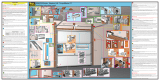
Learn Delete
Controls
w
ww
.Wayne-Dalt
o
n.c
o
m/
access
Fin
d
ou
t
mor
e
:
what’s
OPENING
yo
ur world?
Wi
th Z-Wave
®
t
ech
no
lo
gy
y
ou
can
contr
ol
y
ou
r
light
s,
th
e
rmos
t
at
and
s
t
ar
t
your
mo
r
n
ing
co
f
fee
,
al
l
with
t
h
e sing
le
t
o
u
c
h
of a
but ton
.
P/
N
33598
2
Z-Wave
®
enabled
Attaching Opener To
Support Bracket
Lift and slide the opener over the support
bracket, aligning the mounting studs with
the bracket slots. Loosely fasten to
mounting studs with the (2) 1/4”-20
flange nuts.
Alternately, the disconnect cable can be
pulled to allow motor to pivot up. This will
enable assembly of the support bracket to
the opener first, followed by leveling of the
torque tube and then attachment of support
bracket to mounting surface.
NOTE: Do not tighten 1/4”-20 flange
nuts to opener studs at this time.
Remove the orange label holding the
antenna wire. Straighten antenna wire and
angle it 45 degrees to the right.
NOTE: Do not coil the antenna wire. This
will reduce the radio signal range.
Antenna Wire
(2) 1/4”-20
Flange Nuts
Support
Bracket
Mounting
Studs
45° Angle
Tools Needed:
Step Ladder
Bracket
Slots
Torque Tube
Torque Tube
USING A TAPE MEASURE, MAINTAIN AN EQUAL MEASUREMENT “X” (TOP OF DOOR
TO BOTTOM OF TORQUEMASTER
®
TUBE) AT BOTH ENDS AND THE CENTER.
TOP SECTION
“X” “X” “X”
Tools Needed:
Power Drill
1/8” Drill Bit
7/16” Socket
Driver
Tape Measure
Step Ladder
4
5
IDRIVE
®
FOR TORQUEMASTER
®
INSTALLATION

13
Please Do Not Return This Product To The Store. Call Us Directly! Our Trained Technicians Will Answer Your Questions and/or Ship Any Parts You May Need.
You can reach us Toll Free at 1-888-827-3667 for Consumer Assistance or online at www.wayne-dalton.com
Attaching Disconnect Cable
Attach the loose disconnect cable (located in
opener hardware bag) to the opener with the
“S” hook. Close both ends of the “S” hook
with pliers, to lock assembly together with
pliers.
Thread the disconnect cable (behind the
counterbalance cable) through the hole in
the right hand end bracket, and remove all
slack between opener and right end
bracket.
Close “S” Hook
Disconnect
Cable
S-Hook
Hole in Right
End Bracket
Hole in
End Bracket
Right Side of
End Bracket
Disconnect
Cable
S-Hook
Hole in Right
End Bracket
Hole in
End Bracket
Right Side of End
Bracket
6
Tools Needed:
Step Ladder
Pliers
Torquemaster
®
Torquemaster
®
Plus
/