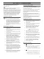
Ingersoll-Rand 302 SERIES Operating instructions
- Type
- Operating instructions

INGERSOLL RAND
302 SERIES
VARIABLE FREQUENCY DRIVE
INSTALLATION AND OPERATION MANUAL
More Than Air. Answers.
Online answers: http://www.air.irco.com
Before installing or starting this unit for the first time, this
manual should be studied carefully to obtain a working
knowledge of the unit and/or the duties to be performed
while operating and maintaining the unit.
RETAIN THIS MANUAL WITH UNIT. This Technical
manual contains IMPORTANT SAFETY DATA and
should be kept with the unit at all times.
C.C.N. : 23046360
REV. C
DATE: DECEMBER 2009

2
TABLE OF CONTENTS
TABLE OF CONTENTS ................................................... 2
SECTION 1 — INTRODUCTION ..................................... 3
SECTION 2 — SAFETY .................................................. 3
SAFETY PRECAUTIONS ....................................................... 3
SHIPMENT INSPECTION / PRE-INSTALLATION CHECK ............... 3
LIFTING .......................................................................... 3
INSTALLATION ................................................................. 3
MECHANICAL INSTALLATION .............................................. 3
OPERATION .................................................................... 4
MAINTENANCE AND REPAIR .............................................. 4
INGERSOLL RAND 302 SERIES VFD WARNINGS AND
PRECAUTIONS ................................................................. 4
WARNING AGAINST UNINTENDED START ............................. 5
SECTION 3 — CONTROL FEATURES AND FUNCTIONS .. 6
STANDARD FEATURES AND FUNCTIONALITY .......................... 6
SECTION 4 — INSTALLATION ..................................... 10
SECTION 5 — DISPLAY AND MENU OPERATION ........ 18
SECTION 6 — COMMISSIONING ................................ 25
PHYSICAL CHECKS .......................................................... 25
RESISTANCE CHECKS ....................................................... 25
KEYPAD OPERATIONS ..................................................... 25
POWER-UP CHECKS ....................................................... 25
INTELLISYS SETUP ........................................................... 25
SECTION 7 — FAULT CODES ...................................... 31
WARNINGS / ALARM MESSAGES ...................................... 31
SECTION 8 — PART LIST ............................................ 39
SECTION 9 — TECHNICAL DATA ................................. 40
SECTION 10 — WIRING DIAGRAM ............................. 46
Refer to Section Indicated
Note
Important or Caution, Safety

3
SECTION 1 — INTRODUCTION
The purpose of this manual is to provide instructions
needed to install, operate, and maintain the Ingersoll-
Rand rotary screw air compressor with the Ingersoll Rand
302 Series Variable Frequency Drive (VFD). The
Operators/Instruction Manual supplied with the
compressor and this Instruction Manual supplied with the
Ingersoll Rand 302 Series VFD should be referenced for
more detailed instructions regarding each of these
components.
The Ingersoll Rand 302 Series VFD will maintain a
constant pressure in compressed air systems by
adjusting the compressor motor’s speed to match the
compressed air usage. Depending on the application and
air demand profile, the Ingersoll Rand 302 Series VFD
system can achieve 25-35% energy savings. Smooth
start-up, reduced machine cycling, lower noise, and
monitoring energy parameters are other benefits from an
Ingersoll-Rand compressor equipped with Ingersoll Rand
302 Series VFD.
SECTION 2 — SAFETY
SAFETY PRECAUTIONS
WARNING: Risk of Danger
WARNING: Risk of Electric Shock
WARNING: Risk of High Pressure
WARNING: Consult Manual
• Before installing or operating the Ingersoll Rand
302 Series VFD, take time to carefully read all
the instructions contained in this manual, all
compressor manuals, and all manuals of any
other peripheral devices that may be installed or
connected to the unit.
• Electricity and compressed air have the
potential to cause severe personal injury or
property damage.
• The operator should use common sense and
good working practices while operating and
maintaining this system. All applicable codes
should be strictly adhered to.
• Maintenance must be performed by adequately
qualified personnel that are equipped with the
proper tools.
SHIPMENT INSPECTION / PRE-
INSTALLATION CHECK
• The crating should be inspected for shipping
damage after the unit has arrived.
• Before unpacking the frequency converter it is
recommended that it is located as close as
possible to the final installation site. Remove the
box and handle the frequency converter on the
pallet, as long as possible.
LIFTING
• Always lift the frequency converter in the
dedicated lifting eyes. Use a bar to avoid
bending the lifting holes of the frequency
converter.
INSTALLATION
• Installation work must only be carried out by a
competent person under qualified supervision.
• A fused isolation switch must be fitted between
the main power supply and the Ingersoll Rand
302 Series VFD.
• The Ingersoll Rand 302 Series VFD should be
mounted in such a location as to allow
operational and maintenance access without
obstruction or hazard and to allow clear visibility
of indicators at all times.
• If raised platforms are required to provide
access to the Ingersoll Rand 302 Series VFD,
they must not interfere with normal operation or
obstruct access. Platforms and stairs should be
of grid or plate construction with safety rails on
all open sides.
MECHANICAL INSTALLATION
• Preparation of the mechanical installation of the
frequency converter must be done carefully to
ensure a proper result and to avoid additional
work during installation. Start taking a close look
at the mechanical drawings at the end of this
instruction to become familiar with the space
demands.
• To perform the mechanical installation the
following tools are needed:
o Drill with 10 or 12 mm drill
o Tape measure
o Wrench with relevant metric sockets (7-17
mm)
o Extensions to wrench
o Sheet metal punch for conduits or cable
glands in IP 21/Nema 1 and IP 54 units
o Lifting bar to lift the unit (rod or tube max. Ø
25 mm (1 inch), able to lift minimum 400 kg
(880 lbs)).
o Crane or other lifting aid to place the
frequency converter in position
o A Torx T50 tool is needed to install the E1
in IP21 and IP54 enclosure types.

4
• Space: Ensure proper space above and below
the frequency converter to allow airflow and
cable access. In addition space in front of the
unit must be considered to enable opening of
the door of the panel.
• Wire access: Ensure that proper cable access is
present including necessary bending allowance.
As the IP00 enclosure is open to the bottom
cables must be fixed to the back panel of the
enclosure where the frequency converter is
mounted, i.e. by using cable clamps.
o All cable lugs/ shoes must mount within the
width of the terminal bus bar
OPERATION
• The Ingersoll Rand 302 Series VFD must only
be operated by competent personnel under
qualified supervision.
• Never remove or tamper with safety devices,
guards or insulation materials fitted to the
Ingersoll Rand 302 Series VFD.
• The Ingersoll Rand 302 Series VFD must only
be operated at the supply voltage and frequency
for which it is designed.
• When main power is switched on, lethal
voltages are present in the electrical circuits and
extreme caution must be exercised whenever it
is necessary to carry out any work on the unit.
• Do not open access panels or touch electrical
components while voltage is applied unless it is
necessary for measurements, tests or
adjustments. Such work should be carried out
only by a qualified electrician equipped with the
correct tools and wearing appropriate protection
against electrical hazards.
• All air compressors and/or other equipment
connected to the unit should have a warning
sign attached stating “THIS UNIT MAY START
WITHOUT WARNING” next to the display panel.
• If an air compressor and/or other equipment
connected to the unit is to be started remotely,
attach two warning signs to the equipment
stating “THIS UNIT CAN BE STARTED
REMOTELY”. Attach one sign in a prominent
location on the outside of the equipment, and
the other sign inside the equipment control
compartment.
MAINTENANCE AND REPAIR
• Maintenance, repairs or modifications must only
be carried out by competent personnel under
qualified supervision.
• If replacement parts are required, use only
genuine parts from the original equipment
manufacturer, or an alternative approved
source.
• Carry out the following operations before
opening or removing any access panels or
carrying out any work on the Ingersoll Rand 302
Series VFD:
i. Isolate the Ingersoll Rand 302 Series
VFD from the main electrical power
supply. Lock the isolator in the “OFF”
position and remove the fuses.
ii. Attach labels to the isolator switch and
to the unit stating “WORK IN
PROGRESS - DO NOT APPLY
VOLTAGE”. Do not switch on electrical
power or attempt to start the CX Box if
such a warning label is attached.
• Make sure that all instructions concerning
operation and maintenance are strictly followed
and that the complete unit, with all accessories
and safety devices, is kept in good working
order.
• The accuracy of sensor devices must be
checked on a regular basis. They must be
calibrated when acceptable tolerances are
exceeded. Always ensure any pressure within
the compressed air system is safely vented to
atmosphere before attempting to remove or
install a sensor device.
• The Ingersoll Rand 302 Series VFD must only
be cleaned with a damp cloth, using mild
detergents if necessary. Avoid the use of any
substances containing corrosive acids or alkalis.
• Do not paint the control faceplate or obscure
any indicators, controls, instructions or
warnings
.
INGERSOLL RAND 302 SERIES VFD
WARNINGS AND PRECAUTIONS
• The frequency converter DC link capacitors
remain charged after power has been
disconnected. To avoid electrical shock hazard,
disconnect the frequency converter from the
mains before carrying out maintenance. Before
doing service on the frequency converter wait at
least the amount of time indicated below:
o 380 - 500 V 90 - 200 kW 20 minutes
250 - 800 kW 40 minutes
o 525 - 690 V 37 - 315 kW 20 minutes
355 - 1200 kW 30 minutes
• The Stop/Reset key on the local control panel of
the Ingersoll Rand 302 Series VFD DOES NOT
disconnect the equipment from the AC line. DO
NOT use the Stop/Reset key as a safety switch.
• The installer must supply correct protective
grounding of the equipment. The user must be
protected against supply voltage, and the motor
must be protected against overload in
accordance with National Electric Code and
local codes.
• To avoid potential shock hazard when servicing
a motor or Ingersoll Rand 302 Series VFD ,
remove all power to all drives with wiring that
shares any conduit to be worked on. If that is
not possible, remove power to the drive and
ground the motor wires at the drive. When the
work has been completed, remove the grounds
before reapplying power to the drive. In general,
a conduit should not contain unshielded power
conductors for more than three PWM operated
motors.

5
• The earth leakage current from the frequency
converter exceeds 3.5 mA. To ensure that the
earth cable has a good mechanical connection
to the earth connection (terminal 95), the cable
cross section must be at least 10 mm
2
or 2 rated
earth wires terminated separately.
• The Electronic Thermal Relay (ETR) in UL/cUL
listed VFDs provides class 20 motor overload
protection in accordance with the NEC in a
single motor applications when parameter 1-40
is set for "TRIP" and parameter 1-24 is set for
the nominal motor rated (nameplate) current.
Protection against motor overload is NOT
included in the factory setting. If this function is
desired, set parameter to 1-40 to data value
ETR trip or data value ETR warning.
ETR function is initialized at 1.16 x rated motor
current.
WARNING AGAINST UNINTENDED
START
• The motor can be brought to a stop by means of
digital commands, bus commands, references
or a local stop, while the Ingersoll Rand 302
Series VFD is connected to the AC line. These
stop functions are NOT sufficient to ensure that
no unintended start occurs and should NOT be
used for personal safety considerations.
• While parameters are being changed, the motor
may start. Consequently, the Stop/Reset button
must be enabled (Parameter 0-41) after which
data can be modified. When the drive is in local
stop the LCP will be flashing. Parameter 0-41
will be changed later during the startup
procedure.
• A motor that has been stopped may start if
faults occur in the electronics of the Ingersoll
Rand 302 Series VFD or if a temporary overload
or a fault in the AC line supply or the motor
connection clears.
WARNING: The Ingersoll Rand 302 Series VFD contains dangerous voltages when connected to line
voltage. After disconnecting from the line wait at least 15 minutes before touching any electrical components. Also make
sure that other voltage inputs have been disconnected, such as external 24 VDC, load-sharing (linkage of DC intermediate
circuit), as well as the motor connection for kinetic back-up. Only a competent electrician should carry out the electrical
installation. Improper installation of the motor or the Ingersoll Rand 302 Series VFD may cause equipment failure, serious
injury or death. Follow this manual and National
WARNING: Electrostatic Discharge (ESD) Precaution. Many electronic components are sensitive to static
electricity. Voltages are so low that they cannot be felt, seen or heard, can reduce the life, affect performance, or completely
destroy sensitive electronic components. When performing service, proper ESD equipment should be used to prevent
possible damage from occurring.
WARNING: It is the responsibility of the user or the person installing the Ingersoll Rand 302 Series VFD to
provide proper grounding, as well as motor overload and branch circuit protection according to the National Electrical Code
and local codes.

6
SECTION 3 — CONTROL FEATURES AND FUNCTIONS
STANDARD FEATURES AND
FUNCTIONALITY
The Ingersoll Rand 302 drive is an external device that is
wired to the compressor’s motors through the starter
panel. The Intellisys controller on the compressor still
starts and stops the compressor, while the Ingersoll Rand
302 Series VFD’s controller varies the compressor’s
motor speed to regulate constant system pressure. The
Ingersoll Rand 302 Series VFD operates in two different
setups:
1) In Setup 1, the Ingersoll Rand 302 Series VFD runs at
constant minimum speed and the compressor is
unloaded.
2) In Setup 2, the Ingersoll Rand 302 Series VFD
regulates a constant pressure and the compressor is
loaded.
The Intellisys controller logic determines which setup the
Ingersoll Rand 302 Series VFD operates.
See Intellisys and Ingersoll Rand 302 Series VFD
Controllers Interface Logic Diagram
As always, the Intellisys controller, set to On / Off Line
mode, will load and unload the compressor, depending
on the system pressure relative to the pressure band
limits. The Ingersoll Rand 302 Series VFD, however, tries
to keep the system pressure within the pressure band as
long as possible.
When the system pressure rises above the target
pressure, the drive will slow the compressor’s motors so
that the compressor supplies less air to the system and
allows the pressure to fall. Likewise, when the system
pressure falls, the drive increases the compressor’s
motor speed so that the compressor supplies more air to
the system.
The compressor with the Ingersoll Rand 302 Series VFD
will only load and unload at minimum speed, unless the
system pressure swings outside the Intellisys pressure
band faster than the drive can react. When the system
pressure rises above the Off Line pressure setpoint, the
blowdown valve opens and the inlet valve closes to
unload the compressor. The load relay, 2CR,
simultaneously opens to switch the drive to Setup 1
(constant, minimum speed).
Conversely, when the system pressure falls below the On
Line pressure setpoint, the blowdown valve closes and
the inlet valve opens to load the compressor. The load
relay, 2CR, simultaneously closes to switch the drive to
Setup 2 (pressure regulation).
Even with the Ingersoll Rand 302 Series VFD wired to
the compressor, the Start button on the Intellisys
controller initiates the full-voltage or star-delta starters.
When the 1M contactor closes, the start relay, 1CR,
closes to start the Ingersoll Rand 302 Series VFD. On
air-cooled, SSR units, the contactors have no power
flowing through them. However, the 1M contactor does
provide power to the constant-speed fan (for a water-
cooled unit) and the oil pump (on Sierra units only). After
the Start process is completed, the compressor will
automatically load and the Ingersoll Rand 302 Series
VFD will try to regulate the pressure.
On SSR air cooled units, the Ingersoll Rand 302 Series
VFD controls the main drive motor and the cooling fan
motor.
On SSR water cooled units, the Ingersoll Rand 302
Series VFD controls the main drive motor. The small
enclosure fan motor gets its power from the compressor
starter.
On Sierra units, the air cooled and water cooled units are
configured the same as the SSR units, except the
externally driven oil pump gets its power from the
compressor starter.

7
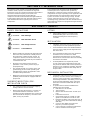
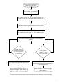
Power at VFD & Compressor
VFD Closes 3CR Relay
Press “START” on Compressor
The Intellisys Closes 1CR Relay to “START” the VFD. The
Compressor begins to run Unloaded with the VFD in SETUP 1
The Intellisys loads the Compressor and closes 2CR Relay
switching to SETUP 2. Variable Speed and Flow operation
continues until the Intellisys Unloads the Compressor.
The Intellisys Unloads the Compressor, opening 2CR Relay.
This switches the VFD to SETUP 1. The Compressor slows
down to minimum speed for the duration of the Unload cycle.
The Compressor continues to cycle between Load and Unload
(2CR Relay closing/opening) until one of the following
happens:
Has the Intellisys
decided the Unload time
has been long enough
to shut the
Compressor off?
Has the VFD Faulted
for any reason?
(I.E.: High Current,
Loss of Phase, etc.)
The Intellisys shuts down the Compressor and
Opens 1CR Relay, stopping the VFD power to
the motor.
The VFD Drive opens 3CR Relay telling the
Intellisys to Stop the Compressor immediately,
similar to the Compressor “Emergency Stop”
button being pressed.
The Compressor and the VFD are
stopped in “Stand-by” mode awaiting a
Start signal.
The Compressor and VFD Stop, both
flashing alarms.
INTELLISYS AND Ingersoll Rand 302 Series VFD CONTROLLERS INTERFACE LOGIC DIAGRAM

8
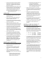
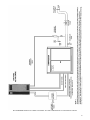
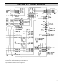
RECOMMENDED INGERSOLL RAND 302 SERIES VFD AND COMPRESSOR SYSTEM INSTALLATION

9
RECOMMENDED INGERSOLL RAND 302 SERIES VFD AND COMPRESSOR SYSTEM INSTALLATION
WITH X-SERIES INTERFACE

10
SECTION 4 — INSTALLATION
When you receive the Ingersoll Rand 302 Series VFD,
inspect it closely. Any indication of careless handling by
the carrier should be noted on the delivery receipt,
especially if the Ingersoll Rand 302 Series VFD will not
be immediately uncrated. Obtaining the delivery person’s
signed agreement to any noted damages will facilitate
any future insurance claims.
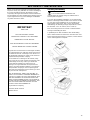
Uncrating and Handling
It is recommended that installation and
commissioning be carried out by an authorized and
trained product supplier.”
To lessen the possibility of damage, it is recommended
that the crated Ingersoll Rand 302 Series VFD be located
as close to the final installation site as possible. If the
Ingersoll Rand 302 Series VFD is not to be installed
immediately, the following storage temperatures need to
be observed: –13°F to +150°F (-25°C to +65°C).
Door and ceiling clearances must be considered when
moving and installing the drive.
A qualified person with a forklift or other similar lifting
device will be needed to remove the drive from the crate.
When unpacking the frequency converter, ensure that the
unit is undamaged and complete.
IMPORTANT
READ THIS
LOST OR DAMAGED GOODS
THOROUGHLY INSPECT THIS SHIPMENT
IMMEDIATELY UPON ARRIVAL
OUR RESPONSIBILITY FOR THIS SHIPMENT
CEASED WHEN THE CARRIER SIGNED
If goods are received short or in damaged condition,
it is important that you notify the carrier and insist on
a notation of the loss or damage across the face of
the freight bill. Otherwise no claim can be enforced
against the transportation company.
If concealed loss or damage is discovered, notify
your carrier at once and request an inspection. This
is absolutely necessary. Unless you do this the
carrier will not entertain any claim for loss or
damage. The agent will make an inspection and
grant a concealed damage notation. If you give the
transportation company a clear receipt for goods
that have been damaged or lost in transit, you do so
at your own risk and expense.
WE, AT INGERSOLL RAND, ARE WILLING TO
ASSIST YOU IN EVERY POSSIBLE MANNER TO
COLLECT CLAIMS FOR LOSS OR DAMAGE, BUT
THE WILLINGNESS ON OUR PART DOES NOT
MAKE US RESPONSIBLE FOR COLLECTION OF
CLAIMS OR REPLACEMENT OF MATERIAL. THE
ACTUAL FILING AND PROCESSING OF THE
CLAIM IS YOUR RESPONSIBILITY.
Ingersoll-Rand Company
Davidson, North Carolina
APDDG-99-79

11
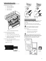
To open the crate: Pry up the metal locking tabs that
secure the top panel of the crate, this will allow access to
the lifting rings on the top of the drive.
See General Arrangement drawings in the VSD
Interconnect Guide for dimensions, weight, and
installation information.
Environment
The area selected for the location of the Ingersoll Rand
302 Series VFD should be free of dust, chemicals, metal
filings, paint fumes and overspray.
Dimensions: NEMA1 & NEMA 12
See General Arrangement drawings in the VSD
Interconnect Guide for dimensions, weight, and
installation information.
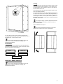
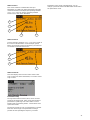
Cooling
The Ingersoll Rand 302 Ingersoll Rand 302 Series VFD is
cooled by means of air circulation. For the cooling air to
escape from the unit a minimum clearance must be left
above and below the unit.
The Ingersoll Rand 302 Ingersoll Rand 302 Series VFD
must be installed vertically.
To avoid overheating the unit, the ambient temperature is
not to exceed 115°F (46°C) and the mean temperature is
not to exceed 104°F (40°C). If the ambient temperature is
in the range of 115°F to 131°F (46°C to 55°C), there is a
possibility of a reduction of the service life of the Ingersoll
Rand 302 Series VFD .
For proper cooling, mount the Ingersoll Rand 302
Series VFD against a flat surface, such as a wall or a
piece of sheet metal.
Top and Bottom Free Space
See General Arrangement drawings in the VSD
Interconnect Guide for Air Space requirements.
DUST CHEMICALS
PAINT SPRAY
METAL FILINGS
OVERSPRAY

12
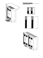
Side by Side Free Air Space
The Ingersoll Rand 302 Series VFD does not require free
air space between drives.

13
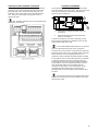
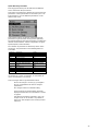
Terminal and Switch Locations
Control Terminals, Ingersoll Rand 302 Series VFD
Drawing reference numbers:
1. 10 pole plug digital I/O.
2. 3 pole plug RS485 Bus.
3. 6 pole analog I/O.
4. USB Connection.
To mount the cable to the terminal:
1. Strip insulation of 9-10 mm
2. Insert a screwdriver1) in the square hole.
3. Insert the cable in the adjacent circular hole.
4. Remove the screw driver. The cable is now
mounted to the terminal.
To remove the cable from the terminal:
1. Insert a screwdriver (1) in the square hole.
2. Pull out the cable.
(1)Max. 0.4 x 2.5 mm
.
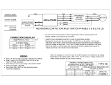
Switches S201, S202, and S801
Switches S201 (A53) and S202 (A54) are used to select
a current (0-20 mA) or a voltage (-10 to 10 V)
configuration of the analog input terminals 53 and 54
respectively.
Switch S801 (BUS TER.) can be used to enable
termination on the RS-485 port (terminals 68 and 69).
See Power Wiring Diagram in the VSD
Interconnect Guide for all electrical terminals.
Default setting:
• S201 (A53) = OFF (voltage input)
• S202 (A54) = OFF (voltage input)
• S801 (Bus termination) = OFF
When changing the function of S201, S202 or
S801 be careful not to use force for the switch over. It is
recommended to remove the LCP fixture (cradle) when
operating the switches. The switches must not be
operated with power on the frequency converter.

14
Ingersoll Rand 302 Series VFD Electrical
Installation
The voltage of the Ingersoll Rand 302 Series VFD is
dangerous when the unit is connected to the AC line.
Incorrect installation of the motor or Ingersoll Rand 302
Ingersoll Rand 302 Series VFD may lead to material
damage or serious injury or death. Follow the instructions
in this manual and comply to National Electrical Codes
(NEC) and local codes and safety guidelines.
DO NOT touch the electrical components of the
Ingersoll Rand 302 Series VFD for at least 15 minutes
after the AC line has been disconnected.
To avoid potential shock hazard when servicing a motor
or variable frequency drives, remove all power to all
drives having wiring that shares any conduit to be worked
on. If that is not possible, remove power to the drive and
ground the motor wires at the drive. When the work has
been completed, remove the grounds before reapplying
power to the drive.
In general, a conduit should not contain unshielded
power conductors for more than three PWM operated
motors.
It is the responsibility of the user or installer to
ensure correct grounding, branch circuit and motor
protection in accordance with the NEC and local codes
Connection of AC Line
Connect the three AC line phases to L1 (91), L2 (92), and
L3 (93) of the terminal block labeled Mains.
See Power Wiring Diagrams in the VSD
Interconnect Guide
To minimize electrical noise, install the drive within
100 feet (30 meters) of compressor.
To avoid electrical noise, do not route high-voltage
motor wires and low-voltage control wires through the
same conduit.
For proper safety, wire compressor and drive to a
common ground.
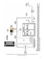
Schematics
The following table lists the electrical schematics that
illustrate the proper way to wire the Ingersoll Rand 302
Series VFD to the compressor. Locate the correct
schematic for the corresponding compressor and refer to
the Wiring Schematics section in this manual. The three
control relays, pressure transducer, and contactor (Sierra
only) should be wired per the proper schematic.
See Compressor Schematics in the VSD
Interconnect Guide
Safety Grounding
Please note that the Ingersoll Rand 302 Series VFD has
a high leakage current and must be grounded
appropriately for safety reasons. Use the ground
terminals (refer to the terminal drawings) which enable
reinforced grounding.
All national and local safety codes must be
observed.
See Power Wiring Diagrams in the VSD
Interconnect Guide
Motor Connection
The power cables from the Ingersoll Rand 302 Series
VFD connect to the motor terminal block located at the
bottom of the compressor’s starter box. The compressor
and fan motors’ leads are connected to the other side of
this block.
The power cables from the compressor/Ingersoll Rand
302 Series VFD system’s main disconnect (DIS1) to the
top of the compressor’s starter contactors should be
sized for the full amp rating of the machine. This setup
allows for the compressor to be quickly converted from
variable speed to constant speed control should the
Ingersoll Rand 302 Series VFD need servicing.
See Power Wiring Diagrams in the VSD
Interconnect Guide

15
Cable and Control Terminal Connection
All terminals for the control cables are located under the
protective cover of the Ingersoll Rand 302 Series VFD.
The protective cover can be removed using care. All
terminals to the control cables are located beneath the
LCP. They are accessed by removing the cover or
opening the door.
Max. 16 AWG (4.0mm2) wire for all Ingersoll Rand
302 Series VFD models.
Transducer Installation
The Ingersoll Rand 302 Series VFD utilizes the signal
from an electronic pressure sensor. The pressure sensor
must be located where it will see the discharge air
pressure of the compressor.
1. Compressor Package Discharge Pressure
Transducer
2. Ingersoll Rand 302 Series VFD Discharge
Pressure Transducer
A pressure transducer (4-20 mA; 0-200 psig / 0-13.8
barg) has been provided as a feedback sensor for the
Ingersoll Rand 302 Series VFD.
It is recommended that the transducer receives its
pressure signal from discharge of the compressor.
The pressure sensor must be connected to the Ingersoll
Rand 302 Series VFD using a shielded (earth screened),
three-conductor (3 core), 20 gauge (0.5mm
2
CSA
minimum), cable no greater than 330ft (100m) in length.
The transducer has a 0.125-in NPT threaded connection.
A 6-ft long cable has also been provided to wire the
transducer into the drive (see proper wiring schematic).
The transducer can be mounted somewhere near the
drive and plastic tubing can be plumbed into the
compressor’s discharge. Or, the transducer can be
mounted at the discharge of the compressor and
shielded cable can be ran between the transducer and
the drive.
Connect the transducer to the Ingersoll Rand 302
Series VFD per the proper wiring schematic in the VSD
Interconnect Guide
1
2

16
Modbus RS-485 Installation and Set-up
RS-485 is a two-wire bus interface compatible with multi-
drop network topology, i.e. nodes can be connected as a
bus, or via drop cables from a common trunk line. A total
of 32 nodes can be connected to one network segment.
Network segments are divided up by repeaters. Please
note that each repeater functions as a node within the
segment in which it is installed. Each node connected
within a given network must have a unique node address,
across all segments. Terminate each segment at both
ends, using either the termination switch (S801) of the
frequency converters or a biased termination resistor
network. Always use screened twisted pair (STP) cable
for bus cabling, and always follow good common
installation practice. Low-impedance ground connection
of the screen at every node is very important, including at
high frequencies. This can be achieved by connecting a
large surface of the screen to ground, for example by
means of a cable clamp or a conductive cable gland. It
may be necessary to apply potential equalizing cables to
maintain the same ground potential throughout the
network, particularly in installations where there are long
lengths of cable. To prevent impedance mismatch,
always use the same type of cable throughout the entire
network. When connecting a motor to the frequency
converter, always use screened motor cable.
Cable: Screened twisted pair (STP)
Impedance: 120 Ohm
Cable length: Max. 1200 m (including drop lines)
Max. 500 m station-to-station
Connect the frequency converter to the RS-485 network
as follows (see also diagram):
1. Connect signal wires to terminal 68 (P+) and
terminal 69 (N-) on the main control board of the
frequency converter.
2. Connect the cable screen to the cable clamps.
Screened, twisted-pair cables are recommended
in order to reduce noise between conductors.
The following EMC precautions are recommended
in order to achieve interference-free operation of the RS-
485 network.
1. Relevant national and local regulations, for
example regarding protective earth connection,
must be observed. The RS-485 communication
cable must be kept away from motor and brake
resistor cables to avoid coupling of high
frequency noise from one cable to another.
2. Normally a distance of 200 mm (8 inches) is
sufficient, but keeping the greatest possible
distance between the cables is generally
recommended, especially where cables run in
parallel over long distances.
3. When crossing is unavoidable, the RS-485
cable must cross motor and brake resistor
cables at an angle of 90 degrees.
See the Dan Foss Design Guide for more detailed
Modbus information

17
Field Conversion
For field conversions contact your local Ingersoll
Rand distributor or air center to ensure that the motor
and controls are appropriate and to determine the proper
speed range of your compressor. Conversion to an SG
Controller may be required in some applications to avoid
operation problems. Check with your Ingersoll Rand
representative.
The Ingersoll Rand 302 Series VFD option can be
supplied as a factory option or as a field conversion kit for
an existing compressor. The field kit includes the
additional pressure transducer, terminals, and three
relays required to convert to Ingersoll Rand 302 Series
VFD operation. On Sierra machines, this kit also includes
an additional electric-driven oil pump and all of its
mounting and piping to provide constant oil pressure for
the inlet valve's hydraulic cylinder. The factory option has
all of the necessary components already installed into the
compressor with the exception of the drive and pressure
transducer.
For a field installation of an existing compressor, the
additional components for the VFD must be installed. The
terminals, relays, and manual motor starter (for Sierra
only) must be installed into the starter panel box per the
assembly drawing. The electric-driven oil pump and its
components (for Sierra only) must be installed per the
assembly drawing specified.
See Compressor Schematics in the VSD
Interconnect Guide
. Prime the Sierra oil pump by filling suction hose
with oil BEFORE applying power to compressor. Once
filled with oil, quickly start and stop compressor until
pump and associated hose are free of vibrations.
The compressor should not be started and
stopped in this manner more than 3 times. Pump seals
may fail if pump runs dry. Once primed, there should be
no need to prime pump again unless compressor has sat
idle for extended time.
If Sierra oil pump was not installed at factory,
check for proper pump rotation. Ensure pump rotates
counter-clockwise while viewing pump from behind
motor.
Starter to Ingersoll Rand 302 Series VFD
Conversion
If the Ingersoll Rand 302 Series VFD is wired as shown
in the schematics in the Wiring Schematics Section of
this manual, a simple procedure is followed to convert the
compressor from operation with the compressor’s
conventional starter to operation with the Ingersoll Rand
302 Series VFD and vice versa.
Changes required for conversion from a conventional
starter to the Ingersoll Rand 302 Series VFD are
described in the following:
1. Disconnect all power from the Ingersoll Rand
302 Series VFD and compressor.
2. Wait at least 15 minutes for power to dissipate
from the Ingersoll Rand 302 Series VFD’s
capacitors.
3. Move the motor leads from the starter contactor
terminal lugs to the tie-off block mounted in the
bottom of the starter box (where the Ingersoll
Rand 302 Series VFD leads come into the
compressor starter box). For air cooled units,
the fan motor leads must also be moved. The
lugs on the bottom of the 1M, 2M, and 1S
contactors may have to be removed to meet the
terminal clearance requirements of some local
electrical codes.
4. Wire the normally-open contact of the Ingersoll
Rand 302 Series VFD alarm relay (3CR) into the
control power wiring as shown in the Wiring
Schematics Section of this manual. Make sure
relays (1CR and 2CR) are properly wired as
shown on the appropriate wiring schematic.
See Compressor Schematics in the VSD
Interconnect Guide
5. Restore power to the machine and Ingersoll
Rand 302 Series VFD .
Ingersoll Rand 302 Series VFD to Starter
Conversion
For conversion back to the starter from the Ingersoll
Rand 302 Series VFD, reconnect the motor leads to the
motor contactors and remove the Ingersoll Rand 302
Series VFD alarm relay (3CR)

18
SECTION 5 — DISPLAY AND MENU OPERATION
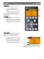
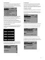
Graphical LCP
The control panel is divided into four functional groups:
1. Graphical display with Status lines.
2. Menu keys and indicator lights - changing
parameters and switching between display
functions.
3. Navigation keys and indicator lights (LEDs).
4. Operation keys and indicator lights (LEDs).
All data is displayed in a graphical LCP display, which
can show up to five items of operating data while
displaying [Status].
Display lines:
a. Status line: Status messages displaying
icons and graphic.
b. Line 1-2: Operator data lines displaying data
defined or chosen by the user. By pressing the
[Status] key, up to one extra line can be added.
c. Status line: Status messages displaying text.
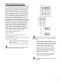
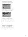
The LCD-Display
The LCD-display has back light and a total of 6 alpha-
numeric lines. The display lines show the direction of
rotation (arrow), the chosen Set-up as well as the
programming Set-up. The display is divided into 3
sections:
Top section: Displays up to 2 measurements in
normal operating status.
Middle section: The top line in the displays up to
5 measurements with related unit, regardless of
status (except in the case of alarm/warning).
Bottom section: This always displays the state
of the frequency converter in Status mode.
Top Section
Middle Section
Bottom Section
The Active Set-up (selected as the Active Set-up in par.
0-10) is shown. When programming another Setup than
the Active Set-up, the number of the programmed Set-up
appears to the right.

19
Display Contrast Adjustment
Press [status] and [▴] for darker display
Press [status] and [▾] for brighter display
Most FC 300 parameter set-ups can be changed
immediately via the control panel, unless a password has
been created via par. 0-60 Main Menu Password or via
par. 0-65 Quick Menu Password
Indicator lights (LEDs):
If certain threshold values are exceeded, the alarm
and/or warning LED lights up. A status and alarm text
appear on the control panel.
The ON LED is activated when the frequency converter
receives mains voltage or via a DC bus terminal or 24 V
external supply. At the same time, the back light is on. •
Green LED/On: Control section is working
Yellow LED/Warn.: Indicates a warning
Flashing Red LED/Alarm: Indicates an alarm
LCP Keys
The control keys are divided into functions. The keys
below the display and indicator lamps are used for
parameter Set-up, including choice of display indication
during normal operation. 130BP045.10
[Status] indicates the status of the frequency converter
and/or the motor. You can choose between 3 different
readouts by pressing the [Status] key:
5 line readouts, 4 line readouts or Smart Logic Control.
Use [Status] for selecting the mode of display or for
changing back to Display mode from either the Quick
Menu mode, the Main Menu mode or Alarm mode. Also
use the [Status] key to toggle single or double read-out
mode. [
Quick Menu] allows quick access to different Quick
Menus such as: -
My Personal Menu
- Quick Set-up
- Changes Made
- Loggings
Use [Quick Menu] for programming the parameters
belonging to the Quick Menu. It is possible to switch
directly between Quick Menu mode and Main Menu
mode.
[Main Menu] is used for programming all parameters. It
is possible to switch directly between Main Menu mode
and Quick Menu mode. Parameter shortcut can be
carried out by pressing down the [Main Menu] key for 3
seconds. The parameter shortcut allows direct access to
any parameter.
[Alarm Log] displays an Alarm list of the five latest
alarms (numbered A1-A5). To obtain additional details
about an alarm, use the arrow keys to maneuver to the
alarm number and press [OK]. You will now receive
information about the condition of your frequency
converter right before entering the alarm mode.
[Back] takes you to the previous step or layer in the
navigation structure.
[Cancel] annuls your last change or command as long as
the display has not been changed.
[Info] supplies information about a command, parameter,
or function in any display window. [Info] provides detailed
information whenever help is needed. Exit info mode by
pressing either [Info], [Back], or [Cancel].
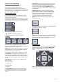
Navigation Keys
The four navigation arrows are used to navigate between
the different choices available in [Quick Menu], [Main
Menu] and [Alarm Log]. Use the keys to move the
cursor.
[OK] is used for choosing a parameter marked by the
cursor and for enabling the change of a parameter.

20
Local Control Key
Four local control are found at the bottom of the control
panel
[Hand On] enables control of the frequency converter via
the LCP. [Hand on] also starts the motor, and it is now
possible to enter the motor speed data by means of the
arrow keys. The key can be selected as Enable [1] or
Disable [0] via par. 0-40 [Hand on] key on LCP. External
stop signals activated by means of control signals or a
serial bus will override a “start” command via the LCP.
The following control signals will still be active when
[Hand on] is activated:
[Hand on] – [Off] – [Auto on]
Reset •
Coasting stop inverse •
Reversing •
Set-up select bit 0-
Set-up select bit 1 •
Stop command from serial communication •
Quick stop •
DC brake
[Off] stops the connected motor. The key can be
selected as Enable [1] or Disable [0] via par. 0-41 [Off]
key on LCP. If no external stop function is selected and
the [Off] key is inactive the motor can be stopped by
disconnecting the voltage.
[Auto On] enables the frequency converter to be
controlled via the control terminals and/or serial
communication. When a start signal is applied on the
control terminals and/or the bus, the frequency converter
will start. The key can be selected as Enable [1] or
Disable [0] via par. 0-42 [Auto on] key on LCP.
An active HAND-OFF-AUTO signal via the digital
inputs has higher priority than the control keys [Hand on]
– [Auto on].
[Reset] is used for resetting the frequency converter after
an alarm (trip). It can be selected as Enable [1] or
Disable [0] via par. 0-43 Reset Keys on LCP.
The parameter shortcut can be carried out by holding
down the [Main Menu] key for 3 seconds. The parameter
shortcut allows direct access to any parameter.
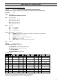
Display Mode
In normal operation, up to 5 different operating variables
can be indicated continuously in the middle section: 1.1,
1.2, and 1.3 as well as 2 and 3.
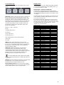
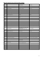
Display Mode - Selection of Read-Outs
It is possible to toggle between three status readout
screens by pressing the [Status] key. Operating variables
with different formatting are shown in each status screen
- see below.
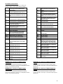
The table shows the measurements you can link to each
of the operating variables. Define the links via par. 0-20,
0-21, 0-22, 0-23, and 0-24.
Each readout parameter selected in par. 0-20 to par. 0-
24 has its own scale and digits after a possible decimal
point. By larger numeric value of a parameter fewer digits
are displayed after the decimal point. Ex.: Current
readout 5.25 A; 15.2 A 105 A.
Operating Variable: Unit:
Par. 16-00
Control Word
hex
Par. 16-01
Reference
[unit]
Par. 16-02
Reference
%
Par. 16-03
Status Word
hex
Par. 16-05
Main Actual Value
%
Par. 16-10
Power
[kW]
Par. 16-11
Power
[HP]
Par. 16-12
Motor Voltage
[V]
Par. 16-13
Frequency
[Hz]
Par. 16-14
Motor Current
[A]
Par. 16-16
Torque
Nm
Par. 16-17
Speed
[RPM]
Par. 16-18
Motor Thermal
%
Par. 16-20
Motor Angle
Par. 16-30
DC Link Voltage
V
Par. 16-32
Brake Energy / s
kW
Par. 16-33 Brake Energy / 2 min kW
Par. 16-34
Heatsink Temp.
C
Par. 16-35
Inverter Thermal
%
Par. 16-36
Inv. Nom. Current
A
Par. 16-37
Inv. Max. Current
A
Par. 16-38
SL Control State
Par. 16-39 Control Card Temp. C
Par. 16-40
Logging Buffer Full
Par. 16-50
External Reference
Par. 16-51
Pulse Reference
Par. 16-52
Feedback [Unit]
Par. 16-53
Digi Pot Reference
Par. 16-60
Digital Input bin
Par. 16-61
Terminal 53 Switch Setting
V
Par. 16-62
Analog Input 53
Par. 16-63
Terminal 54 Switch Setting
V
Par. 16-64
Analog Input 54
Par. 16-65
Analog Output 42
[mA]
Par. 16-66
Digital Output [bin]
Par. 16-67
Freq. Input #29
[Hz]
Par. 16-68 Freq. Input #33 [Hz]
Par. 16-69
Pulse Output #27
[Hz]
Par. 16-70
Pulse Output #29
[Hz]
Par. 16-71 Relay Output
Par. 16-72
Counter A
Par. 16-73
Counter B
Par. 16-80
Fieldbus CTW hex
Par. 16-82
Fieldbus REF 1
hex
Par. 16-84
Comm. Option STW
hex
Par. 16-85
FC Port CTW 1
hex
Par. 16-86
FC Port REF 1
hex
Par. 16-90
Alarm Word
Par. 16-92
Warning Word
Par. 16-94
Ext. Status Word
Page is loading ...
Page is loading ...
Page is loading ...
Page is loading ...
Page is loading ...
Page is loading ...
Page is loading ...
Page is loading ...
Page is loading ...
Page is loading ...
Page is loading ...
Page is loading ...
Page is loading ...
Page is loading ...
Page is loading ...
Page is loading ...
Page is loading ...
Page is loading ...
Page is loading ...
Page is loading ...
Page is loading ...
Page is loading ...
Page is loading ...
Page is loading ...
Page is loading ...
Page is loading ...
-
 1
1
-
 2
2
-
 3
3
-
 4
4
-
 5
5
-
 6
6
-
 7
7
-
 8
8
-
 9
9
-
 10
10
-
 11
11
-
 12
12
-
 13
13
-
 14
14
-
 15
15
-
 16
16
-
 17
17
-
 18
18
-
 19
19
-
 20
20
-
 21
21
-
 22
22
-
 23
23
-
 24
24
-
 25
25
-
 26
26
-
 27
27
-
 28
28
-
 29
29
-
 30
30
-
 31
31
-
 32
32
-
 33
33
-
 34
34
-
 35
35
-
 36
36
-
 37
37
-
 38
38
-
 39
39
-
 40
40
-
 41
41
-
 42
42
-
 43
43
-
 44
44
-
 45
45
-
 46
46


Ingersoll-Rand 302 SERIES Operating instructions
- Type
- Operating instructions
Ask a question and I''ll find the answer in the document
Finding information in a document is now easier with AI
Related papers
-
Ingersoll-Rand X41 User manual
-
-
-
-
-
-
-
-
-
Other documents
-
International comfort products NASA001SC Installation guide
-
Pentair Aurora 7710 IntelliBoost Constant Pressure Variable Speed Booster Systems Owner's manual
-
Ingersoll Rand UP6 Series User manual
-
Danfoss Maneurop VTZ & Compressor Drive Installation guide
-
DAB TR8 SUBMERSIBLE MOTORS Operating instructions
-
-
Franklin Electric VR Spec PAK Owner's manual
-
 RONK ADD-A-PHASE Power Converter User manual
-
Greenheck 101662 Variable Frequency Drive and Control Packages Operating instructions
-
GE BL Series Case Studies
