Broan B6EW Installation guide

Category
Split-system air conditioners
Type
Installation guide
Vertical Wall Mount Air Handler
Please read all information in this manual thoroughly and become familiar with the capabilities
and use of your appliance before attempting to operate or maintain this unit. These instructions
are primarily intended to assist qualified individuals experienced in the proper installation of
this appliance. Some local codes require licensed installation/service personnel for this type
of equipment. Improper installation, service, adjustment, or maintenance may cause explosion,
fire, electrical shock or other hazardous conditions which may result in personal injury or
property damage.
Unless otherwise noted in these instructions, only factory authorized kits or accessories may
be used with this product. Keep this manual where you have easy access to it in the future. If a
problem occurs, check the instructions and follow recommendations given. If these suggestions
don’t eliminate your problem, call your servicing contractor.
DO NOT DESTROY. PLEASE READ CAREFULLY AND
KEEP IN A SAFE PLACE FOR FUTURE REFERENCE.
IMPORTANT
B6EW Series
INSTALLATION INSTRUCTIONS
NOTE: Unit style may appear different depending on model.
2
TABLE OF CONTENTS
Important Safety Information ....................................2
Requirements & Codes ..............................................3
General Information ...................................................4
Before You Install this Unit .........................................4
Locating the Air Handler ............................................4
Minimum Clearances .................................................4
Operation of Air Handler During Construction ...........4
Installation in a Garage .............................................5
Plenums & Air Ducts .................................................5
Acoustical Duct Work .............................................5
Unconditioned Spaces ...........................................5
Filter Requirements ...................................................5
Air Handler Installation ..............................................6
Packaging Removal ...................................................6
Mounting Applications ...............................................6
Connecting Refrigerant Tubing ..................................6
System Depressurization .......................................7
Connecting the Linsets ..........................................7
Condensate Drainage ..............................................7
Electrical Wiring ..........................................................8
Line Voltage ...............................................................8
Grounding..................................................................9
Thermostat Connections ...........................................9
Configuring Blower Speed for Multi-Speed Units ....10
Selecting Continuous Low Speed Fan Operation .... 10
Startup & Adjustments ............................................11
Before You Start the Unit .........................................11
Air Circulation .......................................................11
System Cooling ...................................................11
System Heating ......................................................11
Unit Maintenance ...................................................... 12
Air Filter(s)...............................................................12
Blower Compartment ..............................................12
Blower Fan Wheel ...................................................12
Blower Motor & Assembly .......................................12
Troubleshooting ........................................................12
Figures & Tables .......................................................13
Figure 4. B6EW Physical Dimensions .................13
Table 7. B6EW Specifications..............................13
Table 8. Blower Performance Data.......................14
Wiring Diagrams .................................................15
Figure 5. B6EW 5 kW (1.5, 2, 2.5 & 3 Ton) .............15
Figure 6. B6EW 8 kW/10 kW (1.5, 2, 2.5 & 3 Ton) ..16
Location of Air Handler Components ......................17
Figure 7. Air Handler Components ......................17
Installation CheckList .......................20
IMPORTANT SAFETY INFORMATION
INSTALLER: Please read all instructions before servicing
this equipment. Pay attention to all safety warnings and
any other special notes highlighted in the manual. Safety
markings are used frequently throughout this manual to
designate a degree or level of seriousness and should not
be ignored. WARNING indicates a potentially hazardous
situation that if not avoided, could result in personal injury
or death. CAUTION indicates a potentially hazardous
situation that if not avoided, may result in minor or moderate
injury or property damage.
WARNING:
B6EW Air Handlers leave the factory with a
nitrogen holding charge. Use caution when
preparing coils for field connections. If repairs
make it necessary for evacuation and charging,
it should only be attempted by qualified,
trained personnel thoroughly familiar with this
equipment. Some local codes require licensed
installation service personnel to service this
type of equipment. Under no circumstances
should the equipment owner attempt to install
and/or service this equipment. Failure to comply
with this warning could result in equipment
damage, personal injury, or death.
NITROGEN
HEALTH
FLAMMABILITY
REACTIVITY
0 Minimal Hazard 1 Slight Hazard
1
0
0
WARNING:
ELECTRICAL SHOCK, FIRE OR EXPLOSION
HAZARD
Failure to follow safety warnings exactly could
result in serious injury or property damage.
Improper servicing could result in dangerous
operation, serious injury, death or property
damage.
Before servicing, disconnect all electrical power
to air handler.
When servicing controls, label all wires prior
to disconnecting. Reconnect wires correctly.
Verify proper operation after servicing.
3
REQUIREMENTS & CODES
WARNING:
This unit must be installed in accordance with
instructions outlined in this manual during
the installation, service, and operation of
this unit. Unqualified individuals should not
attempt to interpret these instructions or
install this equipment. Failure to follow safety
recommendations could result in possible
damage to the equipment, serious personal
injury or death.
The installer must comply with all local codes and
regulations which govern the installation of this type
of equipment. Local codes and regulations take
precedence over any recommendations contained in
these instructions. Consult local building codes and the
National Electrical Code (ANSI CI) for special installation
requirements.
This equipment contains nitrogen gas. Installation or
servicing should only be performed by qualified trained
personnel thoroughly familiar with this type of equipment.
All electrical wiring must be completed in accordance
with local, state and national codes and regulations
and with the National Electric Code (ANSI/NFPA 70)
or in Canada the Canadian Electric Code Part 1 CSA
C.22.1.
Installation of equipment may require brazing operations.
Installer must comply with safety codes and wear
appropriate safety equipment (safety glasses, work
gloves, fire extinguisher, etc.) when performing brazing
operations.
Install this unit only in a location and position as specified
on pages 4 & 5. This unit is designed only for indoor
installations and should be located with consideration
of minimizing the length of the supply and return ducts.
See Table 8 (page 14) and the rating plate for proper
circulating airflow data.
Follow all precautions in the literature, on tags, and
on labels provided with the equipment. Read and
thoroughly understand the instructions provided with
the equipment prior to performing the installation and
operational checkout of the equipment.
This air handler may be used for temporary heating
of buildings or structures under construction. See the
guidelines listed on page 4.
Air handler installations in a residential garage must be
installed as specified on page 5.
The information listed below is for reference purposes only
and does not necessarily have jurisdiction over local or state
codes. Always consult with local authorities before installing
any gas appliance.
Duct Systems
US and CANADA: Air Conditioning Contractors Association
(ACCA) Manual D, Sheet Metal and Air Conditioning
Contractors National Association (SMACNA), or American
Society of Heating, Refrigeration, and Air Conditioning
Engineers (ASHRAE) Fundamentals Handbook
Electrical Connections
US: National Electrical Code (NEC) ANSI/NFPA 70
CANADA: Canadian Electrical Code CSA C22.1
General Installation
US: Current edition of the NFPA 90B. For copies, contact
the National Fire Protection Association Inc., Batterymarch
Park, Quincy, MA 02269; or www.NFPA.org
CANADA: NSCNGPIC. For a copy, contact Standard Sales,
CSA International, 178 Rexdale Boulevard, Etobicoke
(Toronto), Ontario, M9W 1R3 Canada
Safety
US: (NFGC) NFPA 54–1999/ANSI Z223.1 and the
Installation Standards, Warm Air Heating and Air
Conditioning Systems ANSI/NFPA 90B.
CANADA: CAN/CGA-B149.1 and .2–M00 National
Standard of Canada. (NSCNGPIC)
4
GENERAL INFORMATION
The unit has been tested and certified by AHRI for capacity
and efficiency and will provide many years of safe and
dependable comfort, providing it is properly installed
and maintained. Abuse, improper use, and/or improper
maintenance can shorten the life of the appliance and
create unsafe hazards. Please read all instructions before
installing the unit.
Before You Install this Unit
This equipment is securely packaged at the time of
shipment and upon arrival should be carefully inspected
for damage prior to installing the equipment at the job
site. Claims for damage (apparent or concealed) should
be filed immediately with the carrier.
The cooling load of the area to be conditioned must be
calculated and a system of the proper capacity selected.
It is recommended that the area to be conditioned be
completely insulated and vapor sealed.
Check the electrical supply and verify the power supply
is adequate for unit operation. The system must be wired
and provided with circuit protection in accordance with
local building codes. If there is any question concerning
the power supply, contact the local power company.
Verify the air delivery of the air handler is adequate to
handle the static pressure drop of the coil, filter, and
duct work.
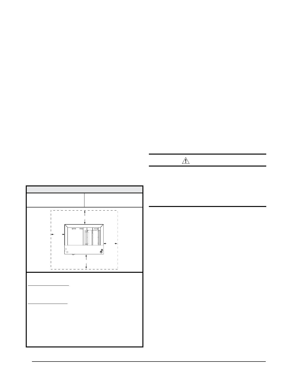
Table 1. Minimum Unit Clearances
INSTALLATION CLEARANCES
Left Side ......... 0 Inches Right Side ...... 0 Inches
Back ............... 0 Inches Front ........... See Notes
NOTES:
Alcove Installations - Allow 24 in. minimum clearance
from front of unit to nearest wall or partition for servicing.
Recommended clearance is 36 in.
Closet installations - require a return air grill installed in
the door or a partially louvered door across the opening
for proper air circulation. For clearances 6” or greater, the
closet must have an open free area of 235 in2 minimum.
For special clearances between 1” - 5”, requirements
are a louvered door with a minimum of 250 in2 (1613
cm2) free area. A fully louvered closet door is strongly
recommended for both installation types.
REAR
RIGHT
SIDE
LEFT
SIDE
FRONT
Locating the Air Handler
Survey the job site to determine the best location for
mounting the unit. Consideration should be given to
availability of electric power, service access, and noise.
The dimensions of the room or alcove must be able
to accommodate the overall size of the unit and the
installation clearances listed in Table 1. Physical
dimensions for this air handler are also shown in Figure
4 (page 13).
The air handler should be installed before routing the
refrigerant tubing.
Minimum Clearances
This appliance must be installed in accordance with
clearances listed in Table 1. The air handler must be
installed with ample clearance for easy access to the
air filter, blower assembly, burner assembly, controls,
and vent connections.
Sufficient clearance for unobstructed airflow through a
louvered door must be maintained in order to achieve
rated performance.
Operation of Air Handler During Construction
CAUTION:
Failure to follow these instructions will void the
factory warranty and may significantly reduce
the life or the performance of the air handler,
and/or result in other unsafe conditions. It is
the responsibility of the installing contractor
to insure these provisions are met.
Operating an air handler in a construction environment
can cause the appliance a variety of problems. Proper
use of commercial portable space heating equipment
during construction is recommended. This air handler
may be used during construction if it is not in violation of
any applicable codes and the following criteria are met:
The installation (including electrical supply, gas supply,
and duct work), must meet all applicable codes and
be permanently installed according to the instructions
supplied with the air handler.
The air handler must be controlled by a properly installed
thermostat that complies with the current provisions
of the NEC (ANSI/NFPA 70) and all applicable codes
having jurisdiction. Thermostat connections must be
made in accordance with instructions supplied with the
air handler and thermostat.
The installation must include a properly installed filter in
the return air system with no by-pass air. The filter must
be inspected frequently and replaced when necessary.
Return air must be supplied unrestricted and located
such that dust and gases from construction activity are
not introduced into the circulating air system.
• Before occupying the structure: The filter must be
replaced or cleaned, the duct work must be inspected
and cleaned of any construction debris, and the furnace
5
must be cleaned and/or repaired if found to be dirty,
damaged, or malfunctioning in any way by a qualified
HVAC technician. The air handler shall be inspected
and approved by applicable local authority even if this
requires redundant inspections.
• The serial number for the air handler used during
construction must be submitted in writing (fax and
email also acceptable). This information will be used to
track the long-term affects of air handler usage during
construction. Proof of this submittal shall be available for
the final inspection of the air handler prior to occupancy.
Installation in a Garage
WARNING:
Do not place combustible materials on or against
the cabinet. Do not place flammable materials,
(gasoline, paint thinners, etc.) or any other
flammable vapors and liquids, in the vicinity
of the air handler.
The B6EW air handler may be installed in a residential
garage with the provision that the unit must be located or
protected to prevent physical damage by vehicles.
Standard for the Installation of Warm Air Heating and
Air Conditioning Systems (NFPA No. 90B).
Design the duct work according to methods described
by the Air Conditioning Contractors of America (ACCA).
The return air duct must have the same free area as
the opening provided on the blower coil unit.
The ducts should be appropriately sized to the capacity
of the air handler to ensure its proper airflow rating.
It is good practice to seal all connections and joints
with industrial grade sealing tape or liquid sealant.
Requirements for sealing ducts vary from region to
region. Consult with local codes for requirements specific
to your area.
Acoustical Duct Work
Certain installations may require the use of acoustical
lining inside the supply duct work.
Acoustical insulation must be in accordance with the
current revision of the Sheet Metal and Air Conditioning
Contractors National Association (SMACNA) application
standard for duct liners.
Duct lining must be UL classified batts or blankets with
a fire hazard classification of FHC-25/50 or less.
Fiber duct work may be used in place of internal duct
liners if the fiber duct work is in accordance with the
current revision of the SMACNA construction standard
on fibrous glass ducts. Fibrous duct work and internal
acoustical lining must be NFPA Class 1 air ducts when
tested per UL Standard 181 for Class 1 ducts.
Unconditioned Spaces
All duct work passing through unconditioned space must
be properly insulated to minimize duct losses and prevent
condensation. Use insulation with an outer vapor barrier.
Refer to local codes for insulation material requirements.
Filter Requirements
B6EW Air Handlers are supplied with a single air filter
when shipped from the factory. Accessing the filter does
not require tools and can be removed from the front of
the unit. See Unit Maintenance (page 12) for filter sizes
and installation information.
WARNING:
Never operate the furnace without a filter in
place. Dust and lint can build up on internal
components, resulting in loss of efficiency,
equipment damage, and possible fire.
Plenums & Air Ducts
This unit is designed only for use with a supply and return
duct. Air ducts should be installed in accordance with the
standards of the National Fire Protection Association
Standard for Installation of Air Conditioning Systems
(NFPA 90A), Standard for Installation of Residence Type
Warm Air Heating and Air Conditioning Systems (NFPA
90B), and all applicable local codes. NFPA publications
are available by writing to: National Fire Protection
Association, Batterymarch Park, Quincy, ME 02269 or visit
www.NFPA.org on the web.
WARNING:
All return ducts must be secured to the air
handler with appropriate fasteners. All return
ducts must be adequately sealed. When return
air is provided through the bottom of the unit,
the joint between the air handler and the return
air plenum must be air tight.
Return air and circulating air ducts must not be
connected to any other heat producing device
such as a fireplace insert, stove, etc. This may
result in fire, explosion, carbon monoxide
poisoning, personal injury, or property damage.
Plenums and air ducts must be installed in accordance
with the Standard for the Installation of Air Conditioning
and Ventilating Systems (NFPA No. 90A) or the
6
AIR HANDLER INSTALLATION
The B6EW Air Handler is shipped ready for vertical upflow
installation and can be mounted directly on a wall or
recessed between framing studs as shown in Figure 1.
Units are also approved for closet or alcove installation
with zero clearance to combustibles. See Table 1 (page
4) for required installation clearances. This appliance is
only for indoor use.
The unit must be leveled at installation and attached to
a properly installed duct system.
The surface that the air handler is mounted on must
provide sound physical support of the unit.
The air handler must be installed so that all electrical
components are protected from water.
If a louvered door is installed across the front of this
unit, the appliance must be mounted flush or behind
front edge of finished wall. See Figure 1.
Packaging Removal
Remove the shipping crate and User’s Manual from the
equipment. Take care not to damage the tubing connections
when removing the crate.
Mounting Applications
Units have a bottom and/or front return. Units are shipped
for installation in a front return application. Front close-
off panel (if supplied) may be discarded. If installed in a
bottom return application, attach bottom access panel to
the front of the unit below the top service panel.
NITROGEN
HEALTH
FLAMMABILITY
REACTIVITY
0 Minimal Hazard 1 Slight Hazard
1
0
0
If the air handler is recessed in a wall, attachment to the
framing studs are through the inside of the front flange.
For hanging applications, these units are provided with
2-piece offset hanging bracket (Figure 1) attached to the
rear of the cabinet. Mounting bracket dimensions are
shown in Figure 4 (page 13).
Connecting Refrigerant Tubing
WARNING:
Evaporator Coils are factory shipped with a
nitrogen charge. Avoid direct face exposure
or contact with valve when gas is escaping.
Always ensure adequate ventilation is present
during the depressurization process. Address
any uncertainties before proceeding. Failure
to comply with this warning could result in
equipment damage, personal injury, or death.
Figure 1. Unit Installation
18"
(457 mm)
24” Clearance from
nearest wall or
partition
Full Louvered
Door
Wall
Mount
Closet
Installation
Alcove
Installation
6”
(152mm)
Typical Closet Door
with Return Air Grill
Installed
OR
Recessed
Wall
Wall
2-Piece
Mounting
Bracket
24” Clearance from
nearest wall or
partition
7
CAUTION:
This unit uses refrigerant R-410A. DO NOT use
any other refrigerant in this unit. Use of another
refrigerant will damage the unit.
• Every effort should be made by the installer to ensure
that the field installed refrigerant containing components
of the system have been installed in accordance with
these instructions and sound installation practices to
insure reliable system operation and longevity.
Always refer to the installation instructions supplied with
the outdoor unit for piping requirements. The suction
and liquid lines must be sized in accordance with the
condensing unit specifications. See Figure 4 (page 13)
for liquid and suction line locations.
• When connecting refrigerant linesets together, it is
recommended that dry nitrogen be flowing through the
joints during brazing. This will prevent internal oxidation
and scaling from occurring.
Refrigerant tubing should be routed in a manner that
minimizes the length of tubing and the number of bends
in the tubing. It should be supported in a manner that
prevents it from vibrating or abrading during system
operation. Tubing should be kept clean of foreign debris
during installation.
If precise forming of refrigerant lines is required, a copper
tubing bender is recommended. Avoid sharp bends and
contact of the refrigerant lines with metal surfaces.
Refrigerant lines should be wrapped with pressure
sensitive neoprene or other suitable material where
they pass against sharply edged sheet metal.
CAUTION:
Before brazing the B6EW, remove the core from
the service port. Failure to comply may result in
leakage at the service valve. Replace the core
and cap once brazing is complete.
The B6EW air handler is charged through service valves
on the end of the liquid tube for each circuit. These must
be removed before brazing the line sets.
System Depressurization
1. Remove the cap from the end of the liquid line.
2. Verify pressurization by depressing the Schrader valve
on the end of the liquid line. Listen for any escaping gas.
If there is no pressure, test the unit for leakage.
If leakage is found, clearly mark the location of the leak
and return the unit to the distributor for processing.
• If no leaks are found, the air handler may be installed.
3. Depress the valve to relieve all pressure from the coil.
Connecting the Linesets
NOTES: Before proceeding, perform steps 1 - 3 in the
System Depressurization section.
1. Route and cut both lineset tubes to proper length in
accordance with the outdoor unit specifications. Verify
the ends are round, clean, and free of any burrs.
2. Connect the suction and liquid lineset tubes.
CAUTION:
It is recommended that a wet rag be wrapped
around the suction line before applying heat.
Failure to keep components cool during brazing
may result in structural damage, premature
equipment failure, or possible personal injury.
3. Braze the individual connections with dry nitrogen flowing
through the joints. This will prevent internal oxidation
and scaling from occurring.
4. Wrap the refrigerant lines with pressure sensitive
neoprene or other suitable material especially where
the lines enter the opening in the sheet metal.
5. Evacuate the system of moisture and non-condensables
to prevent low efficiency operation or damage to the
unit. The suggested range of evacuation is 250 - 500
microns.
6. Charge the system with refrigerant. Refer to the
outdoor unit installation manual for additional charging
instructions.
7. Check the system for leaks, including the lineset and the
brazed joints. NOTE: Apply a soap and water solution on
each joint or union with a small paintbrush. If bubbling
is observed, the connection is not adequately sealed.
8. Properly dispose of all removed parts.
NOTE: On models which use a TXV, it is recommended
to wrap a wet rag around the suction line between the
sensing bulb and the line set braze joint before applying
any heat.
Condensate Drainage
The drain pan that is supplied with this air handler contains
a primary and secondary drain fitting. The condensate is
drained from the unit through two 3/4” male pipe fittings
located on the front side of the unit as shown in Figure
2 (page 8).
CAUTION:
The air handler must be level to ensure proper
condensate drainage. An unlevel installation
may result in structural damage, premature
equipment failure, or possible personal injury.
The method for disposing of condensate varies according
to local codes. Consult your local code or authority
having jurisdiction.
8
Rubber
Washers
Side Drainage
Bottom Drainage
1/2” I.D.
Drain T
ubes
3/4” NPT Adapters
w/ 1/2Hose Barb
NOTES:
1. Field supplied drain lines must be looped to form a trap
.
2.
Drain lines must be routed to the outside of the cabinet.
3. Avoid sharp bends and pinching of the tubing.
Knockouts for condensate drain tubes
(bottom, left, or right side of unit)
Primary & Secondary
Drain Locations
See Notes
See Notes
Figure 2. Condensate Drainage
The drain lines can be routed out the bottom, left or right
side of the air handler, but must maintain a downward
slope to ensure proper condensate drainage. If the
bottom access panel is moved to the front (for bottom
return air), the condensate drain tubes must be routed
thru one of the side openings. DO NOT route the
condensate drain tubes thru the front panel.
Drain pan MUST be drained with field supplied tubing and
looped to form a trap. Failure to install a trap could result
in condensation overflowing the drain pan, resulting in
substantial water damage to surrounding area. Both
drains must be trapped separately. See Figure 2.
It is recommended that both drain tubes have a minimum
internal diameter of 1/2” and be separately routed to
a suitable drain, avoiding sharp bends and pinching of
the lines. Refer to local codes and restrictions for proper
condensate disposal requirements.
• Both adapters should be made of PVC or similar
material and contain a rubber washer. Hand tightened
the adapters to the drain pan. DO NOT use pliers or
any other tools. Overtightening may crack the drain
pan and cause condensate to leak.
During system checkout, inspect the drain line and
connections to verify proper condensate drainage.
ELECTRICAL WIRING
WARNING:
ELECTRICAL SHOCK, FIRE OR EXPLOSION
HAZARD
Failure to follow safety warnings exactly could
result in serious injury or property damage.
Improper servicing could result in dangerous
operation, serious injury, death or property
damage.
• Before servicing, disconnect all electrical power
to air handler.
When servicing controls, label all wires prior
to disconnecting. Reconnect wires correctly.
Verify proper operation after servicing.
• Electrical connections must be in compliance with
all applicable local codes and ordinances, and with
the current revision of the National Electric Code
(ANSI/NFPA 70).
For Canadian installations, the electrical connections
and grounding shall comply with the current Canadian
Electrical Code (CSA C22.1 and/or local codes).
Line Voltage
An electrical disconnect must be located within sight
of and readily accessible to the unit. This switch shall
be capable of electrically de-energizing the outdoor unit.
See unit data label for proper incoming field wiring. Any
other wiring methods must be acceptable to authority
having jurisdiction.
• It is recommended that the line voltage to the unit be
supplied from a dedicated branch circuit containing the
correct fuse or circuit breaker for the unit.
Overcurrent protection must be provided at the branch
circuit distribution panel and sized as shown on the unit
rating label and according to applicable local codes. See
the unit rating plate and Table 2 (page 9) for maximum
circuit ampacity and maximum overcurrent protection
limits.
Refer to the unit wiring label for proper high and low
voltage wiring.
Use only copper wire for the line voltage power supply
to this unit. Use proper code agency listed conduit and
a conduit connector for connecting the supply wires to
the unit.
• If replacing any of the original wires supplied with the
unit, the replacement wire must be copper wire consisting
of the same gauge and temperature rating.
Provide power supply for the unit in accordance with
the unit wiring diagram, and the unit rating plate. The
installer should become familiar with the wiring diagram/
schematic before making any electrical connections to
the unit. See Figures 5 & 6 (pages 15 & 16).
9
All 208/230 Volt units are shipped from the factory wired
for 240 volt operation. For 208V operation, remove the
lead from the transformer terminal marked 240V and
connect it to the terminal marked 208V.
Grounding
WARNING:
The unit cabinet must have an uninterrupted or
unbroken electrical ground to minimize personal
injury if an electrical fault should occur. Do not
use gas piping as an electrical ground!
This unit must be electrically grounded in accordance
with local codes or, in the absence of local codes, with
the National Electrical Code (ANSI/NFPA 70) or the CSA
C22.1 Electrical Code. Use the grounding lug provided in
the control box for grounding the unit.
Minimum Circuit Ampacity & Maximum Overcurrent Protection
Model #
B6EW-
240VAC, 50 & 60Hz 208VAC, 50 & 60Hz
MCA MOP MCA MOP
X18K-05 29.8 30 26.2 30
X18K-08 43.3 45 38.8 40
X24K-05 29.8 30 26.2 30
X24K-08 43.3 45 38.8 40
X24K-10 54.8 60 47.8 50
X25K-05 29.8 30 26.2 30
X25K-08 44.3 45 38.8 40
X25K-10 54.8 60 47.8 50
X30K-05 29.8 30 26.2 30
X30K-08 44.3 45 38.8 40
X30K-10 54.8 60 47.8 50
X36K-05 29.8 30 26.2 30
X36K-08 44.3 45 38.8 40
X36K-10 54.8 60 47.8 50
MCA = Minimum Circuit Ampacity, MOP = Maximum Over-Current
Protection
Table 2. Electrical Rating Data
Thermostat Connections
Thermostat connections shall be in accordance with the
instructions supplied with the thermostat and the indoor
equipment. The low voltage wires must be properly
connected to the units low voltage terminal block.
A single stage thermostat is used with this equipment
and must operate in conjunction with any installed
accessories. Typical AC and air handler hookups are
shown in Figure 3.
The thermostat should be mounted about 5 feet above the
floor on an inside wall. DO NOT install the thermostat on
an outside wall or any other location where its operation
may be adversely affected by radiant heat from fireplaces,
sunlight, or lighting fixtures, and convective heat from
Thermostat
Thermostat
GR
W
Y
GR
W2 E
Y
CO
NOTE: Jumper between
W2 & E is required when
no OD T-stat is used.
Grey
White W1
Red R
Green G
R
W2
OD
Stat
C
O
Y
C
Air Handler Heat pump
Typical Heat Pump & Wall Mount Air Handler Connection
Air Handler Air
Conditioner
Typical AC & Wall Mount Air Handler Connection
Grey C
White W1
Red R
Green G
CY
Figure 3. Typical Thermostat Connections
warm air registers or electrical appliances. Refer to the
thermostat manufacturer’s instruction sheet for detailed
mounting and installation information.
10
Configuring Blower Speed for Multi-Speed Units
The blower speed is preset at the factory for operation
at the same speed for heating and cooling, by using the
jumping terminal on the blower motor and connecting it
to the desired speed with both the red and black wires
connected to the jumping terminal.
CAUTION:
To avoid personal injury or property damage,
make sure the motor leads do not come into
contact with any uninsulated metal components
of the unit.
For optimum system performance and comfort, it may be
necessary to change the factory setting speed. See Table
8 (page 14) for airflow data.
1. Disconnect all electrical power to the unit and remove
the upper door.
2. Change DIP switch according to desired blower speed.
See Table 3 for DIP switches setting.
Table 4. Control Board Operation
Control Signal & MODE Operation Total kW Board Action
W
(EHEAT)
ON
5 kW Stage 1 Heat on instantly
Heat blower on after 3 second delay
8 kW/10 kW
Stage 1 Heat on instantly
Heat blower on after 3 second delay
Stage 2 Heat on after 5 seconds delay
OFF Heat stages off instantly
Blower off after 15 second delay
W & Y
(AUX HEAT)
ON
5 kW Stage 1 Heat on instantly
Cool blower on after 3 second delay
8 kW/10 kW
Stage 1 Heat on instantly
Cool blower on after 3 second delay
Stage 2 Heat on after 5 seconds delay
OFF Heat stages off instantly
Heat blower turns off after 40 second delay
G
(FAN)
ON Cool blower on after 3 second delay
OFF Cool blower off instantly
Y
(HP & COOL)
ON Cool Blower on after 3 second delay
OFF Cool Blower off after 40 second delay
5 Speed Motor Terminals
Terminal M1 = Low speed
Terminal M2 = Medium Low speed
Terminal M3 = Medium speed
Terminal M4 = Medium Hi speed
Terminal M5 = Hi speed
CAUTION:
To prevent overheating of the air handler, make
sure the DIP switch is not in the M1 position
when the heater is operating at 10kW.
3. Replace the upper door and secure it to the unit.
4. Restore power to the unit.
Selecting Continuous Low Speed Fan Operation
(Standard Blower)
The air handler is equipped with the option of continuous
low speed fan operation. When G is energized without Y/
Y2, the air handler will operate using the cooling speed.
With G & Y/Y2 or Y/Y2 is energized, the air handler will
operate in the selected cooling speed (including 40 sec
blower-off delay).
SET HEAT COOL
5432112345
M1 Off Off Off Off On On Off Off Off Off
M2 Off Off Off On Off Off On Off Off Off
M3 Off Off On Off Off Off Off On Off Off
M4 Off On Off Off Off Off Off Off On Off
M5 On Off Off Off Off Off Off Off Off On
Table 3. DIP Switch Setting
11
STARTUP & ADJUSTMENTS
WARNING:
The evaporator coil is shipped from the factory
with a nitrogen charge. Use caution when
preparing coils for field connections. If repairs
make it necessary for evacuation and charging,
it should only be attempted by qualified,
trained personnel thoroughly familiar with this
equipment. Some local codes require licensed
installation service personnel to service this
type of equipment. Under no circumstances
should the equipment owner attempt to install
and/or service this equipment. Failure to comply
with this warning could result in equipment
damage, personal injury, or death.
NITROGEN
HEALTH
FLAMMABILITY
REACTIVITY
0 Minimal Hazard 1 Slight Hazard
1
0
0
5. Inspect the unit rating plate for the proper type of
refrigerant and quantity.
6. Weigh in the proper amount of new (or reclaimed)
refrigerant.
Air Circulation
Running the Blower Continuously
Set the thermostat’s system mode to OFF and the
thermostat’s fan mode to ON. The blower motor should
run continuously. Check for air delivery at the register(s).
Ensure that there are no obstructions at the registers or
in the ducts.
Turning the Blower Off
Set thermostat’s fan mode to AUTO, the blower will shut
down immediately.
System Cooling
1. Set the thermostat’s system mode to COOL and fan
mode to AUTO. Lower the thermostat’s temperature
mode below room temperature and observe that the
blower energizes. Check the air being discharged at
the register is cooler than room temperature. Verify unit
refrigerant pressures are in order.
2. Allow the unit to run for several minutes and then set
the thermostat’s temperature above room temperature.
Verify the blower cycles off with the thermostat.
System Heating
1. Set the thermostat’s system mode to HEAT and the fan
mode to AUTO. Increase the thermostat’s temperature
above room temperature and observe that the blower
energizes. Check the air being discharged at the register
is warmer than room temperature.
2. Allow the unit to run for several minutes and then set
the thermostat’s temperature below room temperature.
Verify the blower cycles off with the thermostat.
Before You Start the Unit
Prior to start-up, complete the following inspections:
Verify the unit is level and mounted securely to the wall.
Also make sure the air handler is properly located with
adequate clearances for servicing the unit as listed in
Table 1 (page 4).
Check condensate drain line(s) for proper drainage.
Verify the surrounding area and top of the unit is free
from obstructions and debris.
Check all duct connections. Make sure the duct work
is adequately sealed to prevent air leakage.
Check all coil connections for leaks.
Verify that the line voltage power leads are securely
connected and the unit is properly grounded.
Verify the thermostat is wired correctly. Make sure all
low voltage wires are securely connected to the correct
leads of the low voltage terminal strip.
Verify the power supply branch circuit overcurrent
protection is sized properly.
Verify filter is properly and securely installed.
IMPORTANT: Before you start the unit, perform the
following procedures to install the initial charge on units
that are factory shipped with a nitrogen holding charge:
1. Read all installation instructions first.
2. Purge the nitrogen holding charge.
3. Evacuate the unit to 350 - 500 microns.
4. Allow the unit to remain under vacuum for at least 30
minutes.
12
UNIT MAINTENANCE
Proper maintenance is most important to achieve the best
performance from a furnace. Follow these instructions for
years of safe, trouble free operation.
WARNING:
ELECTRICAL SHOCK, FIRE OR EXPLOSION
HAZARD
Failure to follow safety warnings exactly could
result in serious injury or property damage.
Improper servicing could result in dangerous
operation, serious injury, death or property
damage.
Before servicing, disconnect all electrical power
to air handler.
When servicing controls, label all wires prior
to disconnecting. Reconnect wires correctly.
Verify proper operation after servicing.
These maintenance instructions are primarily intended
to assist qualified technicians experienced in the proper
maintenance and operation of this appliance.
Always reinstall the doors on the furnace after servicing
or cleaning/changing the filters. Do not operate the
furnace without all doors and covers in place.
Verify that the thermostat is properly installed and is
not being affected by drafts or heat from lamps or other
appliances.
To achieve the best performance and minimize
equipment failure, it is recommended that a yearly
maintenance checkup be performed. At a minimum,
this check should include the following items:
Air Filter(s)
WARNING:
Never operate the furnace without a filter in
place. Dust and lint in the return air can build
up on internal components, resulting in loss of
efficiency, equipment damage, and possible fire.
B6EW Air Handlers are supplied with a single air filter
when shipped from the factory. It is recommended that
the filter be cleaned or replaced monthly. Newly built or
recently renovated homes may require more frequent
changing until the construction dust has minimized. Filter
sizes shown in Table 5 are available at most local retailers.
Filters designed to remove smaller particles such as
pollen, may require additional maintenance.
Blower Compartment
Dirt and lint can create excessive loads on the motor
resulting in higher than normal operating temperatures
and shortened service life. It is recommended that the
blower compartment be cleaned of dirt or lint that may
have accumulated in the compartment or on the blower
and motor as part of the annual inspection.
Blower Fan Wheel
Inspect the blower wheel blades for accumulations of dirt
and clean if necessary. Inspect mounting nut for tightness
when done.
Blower Motor & Assembly
Inspect the blower assembly and motor mounting
brackets for tightness and corrosion. Correct deficiencies
if necessary. The blower motor contains sealed bearings
and under normal operating conditions, no maintenance
is necessary for the life of the equipment.
TROUBLESHOOTING
If the air handler fails to operate, check the following:
• Is the electric turned on?
• Is the thermostat operating properly?
• Are the blower compartment door(s) in place?
• Is the furnace disconnect closed?
Has the circuit breaker tripped or the control board fuse
burned open?
• Are any manual reset switches open?
• Is the filter dirty or plugged?
Is the LED on the furnace control board constantly ON?
If not, refer to Table 6 to determine fault condition.
Red LED (AN2) Diagnostic Description
OFF Control Fault (No Power)
Flash Blower Fault
ON Normal Operation
Table 6. Furnace Control Board Fault Conditions
Model Number Filter Size
B6EW-X18K 16” x 20 x 1”
B6EW-X24K
B6EW-X25K 20” x 20 x 1”
B6EW-X30K 20” x 20 x 1”
B6EW-X36K 24” x 20 x 1”
Table 5. Filter Sizes
13
“C”
18 5/8
1
1
Ø3/8" K.O.
3/4
“B”
1 1/2
1 1/2
2 5/86 1/4
10 1/2
19
10 1/2
Drain
Knockout
Optional
Refrigerant
Line Entry
1 5/8
20 1/2
1 5/8
Liquid Line
2 1/8
Suction
Line
1
7/8
1 1/4
1
1 7/8
3/4
Ø3/8" Low
Voltage
Optional
Refrigerant
Line Entry
Drain
Knockout
Ø1 1/8" K.O.
Power Entry
Ø1 1/8" K.O.
Power Entry
1 5/8
FRONT VIEW RIGHT
SIDE
LEFT
SIDE
BOTTOM
VIEW
3/4
TOP
VIEW
Primary & Secondary
Drain Connections
“A”
Table 7. B6EW Specifications
MODEL
B6EW-
REFRIGERANT CONNECTIONS SUPPLY AIR
DUCT DIMENSION A B
SUCTION DIA. LIQUID DIA.
X18K 3/4 3/8 9 x 17 1/4 36 3/8 9 1/2
X24K 3/4 3/8 9 x 17 1/4 36 3/8 9 1/2
X25K 3/4 3/8 9 x 17 1/4 43 1/2 9 1/2
X30K 3/4 3/8 9 x 17 1/4 43 1/2 9 1/2
X36K 3/4 3/8 15 x 17 1/4 43 1/2 15 1/2
Figure 4. B6EW Physical Dimensions
FIGURES & TABLES
8” 8”
7/8”
20 3/8”
10 3/16”
Ø 7/32”
(3 places)
3 1/2”
1 3/4”
1 3/4”
.07”
MTG BRACKET
14
AIRFLOW DATA
Table 8. Blower Performance Data
X18K/X24K
Dry Coil ESP 0.1 0.2 0.3 0.4 0.5 0.6 0.7 0.8
M1 712 678 644 604 558 514 475 436
M2 896 859 831 805 764 731 697 657
M3 980 927 915 885 843 813 768 730
M4 1080 1040 1026 993 976 942 915 878
M5 1165 1128 1118 1065 1048 1020 995 964
X25K/X30K
Dry Coil ESP 0.1 0.2 0.3 0.4 0.5 0.6 0.7 0.8
M1 773 728 698 653 608 571 518 484
M2 943 917 901 861 824 783 743 701
M3 1034 993 959 942 913 869 836 795
M4 1163 1128 1099 1067 1054 1019 967 942
M5 1245 1215 1191 1155 1124 1102 1068 1047
X36K
Dry Coil ESP 0.1 0.2 0.3 0.4 0.5 0.6 0.7 0.8
M1 805 758 706 645 580 518 461 412
M2 1026 983 934 889 839 792 732 667
M3 1121 1080 1039 1001 947 902 846 791
M4 1275 1235 1193 1152 1112 1070 1024 971
M5 1388 1349 1302 1261 1226 1185 1141 1092
NOTES:
1) Airflow is shown in cfm, +/- 5%.
2) External static pressure is shown in inches W.C.
3) All airflows are measured without filter and with dry coil. For filter, subtract .08” external static pressure. For wet
coil, subtract .1” external static pressure.
4) See unit nameplate or installation instructions for maximum recommended external static pressure.
15
WIRING DIAGRAMS
Figure 5. Wiring Diagram for B6EW-X18K, B6EW-X24K, B6EW-X25K, B6EW-X30K, & B6EW-X36K
(1.5, 2, 2.5, & 3 Ton Units)
711465A
1. The blower motor speed tap connection may not be as shown.Refer to installation instructions provided
with unit to set DIP switches for theappropriate heating and cooling speed setting for your application.
2. Disconnect all power before servicing.
3. The transformer may have a dual voltage primary tap. Match the tap positionwith the supply voltage used.
4. If the internal wiring is replaced, use only 105°C copper wire of the same gauge.
NOTES:
Wall Mount Air Handler ECM (5KW)
WIRING DIAGRAM
FIELD WIRING
LEGEND:
LOW VOLTAGE
HIGH VOLTAGE
WIRING DIAGRAM
(Replaces 7114650)
09/15
Remarques
1. Le connecteur de vitesse du moteur du ventilateur
peut différer de l’illustration. Consultez les
Instructions d’installation.
2. Débranchez toutes les sources d’alimentation avant
l’entretien.
3. Le transformateur peut avoir un robinet principal à
double tension. Agencez la position du robinet au
type de tension de l’installation.
4. Si le câblage interne est remplacé, utilisez seulement
un fil de cuivre 105° C du même gabarit.
CIRCUIT
BREAKER
LIMIT
ELEMENT RELAY ELEMENT
SUPPLY VOLTAGE
CONTROL
BOARD
R
C
L2
L1
L1
L2
L2
YWGCR
TRANSFORMER
24V
208V
240V
ECM
MOTOR
HEATER
ORANGE
GRAY
COM
NO
L1
HEAT
OFF
ON
COOL
1
5678
234
BLACK
BLUE
YELLOW
ORANGE
RED
BROWN
WHITE
RED
YELLOW/GREEN
5 4 3 2 1 1 2 3 4 5
BLACK
AC RELAY
COM NO
RED
BLACK
WHITE
GRAY
YELLOW
WHITE
GRAY
GREEN
RED
BLACK
BLACK WHITE
RED
BLACK
HARNESS
RED
WHITE
GRAY
RED
16
NOTES:
Wall Mount Air Handler ECM (8KW/10KW)
WIRING DIAGRAM
FIELD WIRING
LEGEND:
LOW VOLTAGE
HIGH VOLTAGE
WIRING DIAGRAM
1. The blower motor speed tap connection may not be as shown.Refer to
installation instructions provided with unit to set DIP switches for the
appropriate heating and cooling speed setting for your application.
2. Disconnect all power before servicing.
3. The transformer may have a dual voltage primary tap.
Match the tap positionwith the supply voltage used.
4. If the internal wiring is replaced, use only 105°C copper wire of the same gauge.
7114660
10/14
Remarques
1. Le connecteur de vitesse du moteur du ventilateur peut différer de
l’illustration. Consultez les Instructions d’installation.
2. Débranchez toutes les sources d’alimentation avant l’entretien.
3. Le transformateur peut avoir un robinet principal à double tension. Agencez
la position du robinet au type de tension de l’installation.
4. Si le câblage interne est remplacé, utilisez seulement un fil de cuivre 105° C
du même gabarit.
CONTROL
BOARD
R
C
L2
L1
L1
L1
L2
L2
YWGCR
CIRCUIT
BREAKER
TRANSFORMER
24V
208V
240V
ELEMENT RELAY
ELEMENT RELAY
ELEMENT
ELEMENT
SUPPLY VOLTAGE
ECM
MOTOR
HEATER
BLUE
ORANGE
LIMIT
2
1
4
3
COMNO
COM
NO
GRAY
1
5678
234
BLACK
BLUE
YELLOW
ORANGE
RED
WHITE
BROWN
YELLOW/GREEN
HEAT
OFF
ON
COOL
5 4 3 2 1 1 2 3 4 5
BLACK
WHITE
AC RELAY
COM NOCOM NO
RED
BLACK
WHITE
GRAY
YELLOW
RED
GREEN
BLACK RED
RED
RED
BLACK
BLACK
BLACK WHITE
HARNESS
RED
BLACK
GRAY
GRAY
WHITE
GRAY
WHITE
GRAY
WHITE
RED
RED
Figure 6. Wiring Diagram for B6EW-X18K, B6EW-X24K, B6EW-X25K, B6EW-X30K, & B6EW-X36K
(1.5, 2, 2.5, & 3 Ton Units)
17
LOCATION OF AIR HANDLER COMPONENTS
Figure 7. Air Handler Components
Element Relay
Limit
Switch
Heating Element
Assembly
Circuit
Breaker (60A)
Blower Motor
Motor Mount
PCB Board
Blower Wheel
Distributor
Mounting
Bracket
Coil
Assembly
Drain Pan
Blower Housing
Transformer
18
19
INSTALLATION CHECKLIST
INSTALLER NAME:
CITY: STATE:
INSTALLATION ADDRESS:
CITY: STATE:
UNIT MODEL #
UNIT SERIAL #
Minimum clearances per Table 1
(page 4)? YES NO
Is the unit properly installed and
leveled? YES NO
Does condensate drain properly
in both drain tubes? YES NO
Has the owner’s information been
reviewed with the home-owner? YES NO
Has the literature package been
left near the appliance? YES NO
ATTENTION INSTALLERS:
It is your responsibility to know this product better than your customer. This includes being able to install the product according to strict safety
guidelines and instructing the customer on how to operate and maintain the equipment for the life of the product. Safety should always be
the deciding factor when installing this product and using common sense plays an important role as well. Pay attention to all safety warnings
and any other special notes highlighted in the manual. Improper installation of the furnace or failure to follow safety warnings could result in
serious injury, death, or property damage.
These instructions are primarily intended to assist qualified individuals experienced in the proper installation of this appliance. Some local
codes require licensed installation/service personnel for this type of equipment. Please read all instructions carefully before starting the
installation. Return these instructions to the customer’s package for future reference.
ELECTRICAL SYSTEM:
Electrical connections tight? YES NO
Line voltage polarity correct? YES NO
Supply Voltage: ___________________________________(V)
Has the thermostat been calibrated? YES NO
Is the thermostat level? YES NO
Is the heat anticipator setting correct? YES NO
Specifications & illustrations subject to change without notice or incurring obligations (11/20).
O’Fallon, MO, © Nortek Global HVAC LLC 2020. All Rights Reserved.
10348710
(Replaces 709207C)
  • Page 1 1
  • Page 2 2
  • Page 3 3
  • Page 4 4
  • Page 5 5
  • Page 6 6
  • Page 7 7
  • Page 8 8
  • Page 9 9
  • Page 10 10
  • Page 11 11
  • Page 12 12
  • Page 13 13
  • Page 14 14
  • Page 15 15
  • Page 16 16
  • Page 17 17
  • Page 18 18
  • Page 19 19
  • Page 20 20

Broan B6EW Installation guide

Category
Split-system air conditioners
Type
Installation guide

Ask a question and I''ll find the answer in the document

Finding information in a document is now easier with AI