Page is loading ...

®
C US
Read and understand this manual. Improper installation, adjustment, alteration,
service or maintenance can cause serious injury, property damage or even death.
For assistance or additional information consult a qualified installer, service
agency or the gas supplier.
DANGER
Glass doors on gas fireplaces are extremely hot while the fireplace is on and
remain hot even after the fireplace has been turned off. Safety screens are
available and can reduce the risks of severe burns. Please keep children away
from the fireplace at all times.
CAUTION
Do not store or use gasoline or any other flammable vapors and liquids in the vicinity of
this or any other gas burning appliance. A fire or explosion my occur causing serious
injury, property damage or even death.
WARNING
Installer: Leave this manual with the appliance. Do not remove.
Consumer: Retain this manual for maintenance and future reference. Do not Discard.
NOTICE
IF YOU SMELL GAS
Do not try to light any appliance.
Do not touch any electrical switch; do not use any phone in your building.
Immediately call your gas supplier from a neighbor's phone. Follow the gas
supplier's instructions.
If you cannot reach your gas supplier, call the fire department.
DANGER
Irritant
Cutting
Watch your step
Slippery floor
High temperatures
Glass hazard
Danger of suffocation
High voltage
Toxic
Flammable materials
Corrosive
Fork lift trucks
Danger overhead crane
Explosion risk
Oxidising
Danger of death
Biohazard
Laser Radiation
Danger of entrapment
Hot surface
General Warning
Blank
Gas bottles
Watch for
falling objects
Electricity
Danger for cutter
Entrapment hazard
Battery hazard
Rotating parts
Low temperature
Strong magnetic field
Optical radiation
Non ionizing
radiation
Radiation
Hazardous to the
Environment
Danger of harming
your hands
Irritant
Cutting
Watch your step
Slippery floor
High temperatures
Glass hazard
Danger of suffocation
High voltage
Toxic
Flammable materials
Corrosive
Fork lift trucks
Danger overhead crane
Explosion risk
Oxidising
Danger of death
Biohazard
Laser Radiation
Danger of entrapment
Hot surface
General Warning
Blank
Gas bottles
Watch for
falling objects
Electricity
Danger for cutter
Entrapment hazard
Battery hazard
Rotating parts
XG0193 103111.1
P38DF Indoor
Prestige Series
Residential
Fireplace
Installation & Maintenance Manual
Langley, BC V4W 4A1 | Ferndale, WA 98248

You must read and understand this manual prior to installation, operation or
troubleshooting this appliance. Please retain this owner’s manual for furure reference
and maintenance.
NOTICE
Table of Contents
P38DF* Indoor Gas Fireplace
XG0193 - 103111.1
.................................................................................3
Before you start
.................................................................................4
Installation Checklist ...............................................................................4
Installation Overview and Product Dimensions .....................5
Framing & Clearances ...........................................................6
Framing the Fireplace .............................................................................6
Clearances .................................................................................6
Venting .................................................................................7
Notes for Planning Venting ..........................................................................7
▪ Section 3-1: Converting to Rear Vent
..................................................7
▪ Section 3-2: Installing PVTK-1 ..............................................................8
▪ Section 3-2-1 V
enting Layout
..........................................................8
▪ Section 3-2-2: V
enting Components
....................................................9
▪ Section 3-3: Installing W
all Mounted Direct Vent Termination
............10
▪ Section 3-3-1: Venting Layout Wall Mounted Termination ........11-13
▪ Section 3-3-2: V
enting Components
..............................................14
▪ Section 3-3-3:Heat Shields ............................................................15
Wiring ...............................................................................16
▪
........................................................................16
▪
................................................................16
Installing the Gas Line .........................................................17
Fuel Conversion
...............................................................17
Gas Pressure ...................................................................17
Gas Connection
...............................................................17
Finishing ..............................................................................18
▪ Finishing
Around the Fireplace
.....................................................18
▪Fireplace Facing ............................................................................18
▪ Installing the Nailing Flange Extension .........................................18
Removing the door ..............................................................19
Installing the Accessories .....................................................20
▪ Installing the Firestones ................................................................20
............................................................................21
▪ For
Your Safety - READ BEFORE LIGHTING
..............................21
▪ Lighting Instructions ......................................................................21
▪
Turn Off Gas to Appliance
............................................................21
........................................................................22 - 24
▪ General ...............................................................................22
▪ Cleaning
...............................................................................22
▪ Replacing Light Bulbs ...................................................................23
▪
Troubleshooting
............................................................................24
▪ Replacement Parts List ................................................................24
A. Termination Locations ...............................................................25
B. W
arranty
...............................................................................26
C. State of Massachusetts. ...........................................................27

Indicates a hazardous situation which, if not
avoided, WILL result in death or serious
injury or property damage.
Indicates a hazardous situation which, if not
avoided, COULD result in death or serious
injury or property damage.
Indicates a hazardous situation which, if not
avoided, WILL result in minor or moderate
injury.
Address practices that are important, but
not related to personal injury
DANGER WARNING
CAUTION NOTICE
P38DF* Indoor Gas Fireplace
Safety Alert Key
Introduction
XG0193 -103111.1
INTRODUCTION
Congratulations on your purchase of a .
With over 30 years of experience, Montigo is committed to providing you
with a gas replace that is not only a beautiful addition to your space, but
that is also designed and manufactured to the highest safety, reliability
and engineering standards.
We strongly encourage you to read and carefully follow the instructions
laid out in this Installation, Operation and Maintenance Manual and retain
it for your future reference. Pay special attention to all cautions, warnings,
and notices throughout this manual intended to ensure your safety.
This manual covers installation, operation and maintenance. Lighting,
operation and care of this replace can be easily performed by the
homeowner. All installation and service work should be performed by
a qualied or licensed installer, plumber or gas tter as certied by the
state, province, region or governing body where the replace is being
installed.
This installation, operation and maintenance manual is applicable to
the models described to the right. Refer to your rating plate to verify
included options.
The Montigo warranty will be voided by, and Montigo disclaims any
responsibility for, the following actions:
► Modication of the replace and/or components including
Direct-Vent assembly or glass doors.
► Use of any component part not manufactured or approved
by Montigo in combination with this Montigo replace system.
► Installation other than as instructed in this manual.
Consult your local Gas Inspection Branch on installation requirements
for factory-built gas replaces. Installation & repairs should be done by
a qualied contractor.
Hot glass will cause
burns. Do not touch
glass until unit is cooled.
Never allow children to
touch glass.
Irritant
Cutting
Watch your step
Slippery floor
High temperatures
Glass hazard
Danger of suffocation
High voltage
Toxic
Flammable materials
Corrosive
Fork lift trucks
Danger overhead crane
Explosion risk
Oxidising
Danger of death
Biohazard
Laser Radiation
Danger of entrapment
Hot surface
General Warning
Blank
Gas bottles
Watch for
falling objects
Electricity
Danger for cutter
Entrapment hazard
Battery hazard
Rotating parts
Low temperature
Strong magnetic field
Optical radiation
Non ionizing
radiation
Radiation
Hazardous to the
Environment
Danger of harming
your hands

P38DF* Indoor Gas Fireplace
XG0193 - 103111.1
Installation
The Direct Vent replace must be installed in accordance with
these Instructions. Carefully read all the Instructions in this manual
rst. Consult the Local Gas Branch to determine the need for a permit
prior to starting the installation. It is the responsibility of the installer to
ensure this replace is installed in compliance with the manufacturers
instructions and all applicable codes.
Due to high operating temperatures, this appliance should be located out of traffic &
away from furniture and draperies.
Children and adults should be alerted to the hazards of the high surface temperature,
which could cause burns or clothing ignition.
Young children should be carefully supervised when they are in the same room as the
appliance.
Clothing or other flammable materials should not be placed on or near the appliance.
CAUTION
When this appliance is installed directly on any combustible material other than wood
flooring, it must be installed on a metal or wood panel extending the full width and
depth of the appliance or a fire will occur causing serious injury, property damage or
even death.
DANGER
Determine the desired install location of your replace.
See , Dimensions on and refer to the Framing
for details.
Select the location of your termination and resulting vent run.
.
Should it be impossible to meet the venting requirements laid
out in : Venting, please contact a local Montigo dealer
regarding the use of a Montigo Power Vent.
Lay out the Vent run; calculating the required elbows and straight
runs of 5"/8" flex or rigid pipe.
Layout Electrical Requirements Refer to Wiring, for
Details.
Refer to Installing the Gas Line, for details on the
gas connection and access.
Refer to local codes and guidelines for installation requirements.
:
• must conform to the local codes or in the
absence of local codes to the current version of Natural Gas and Propane
Installation Code, CSA B149. Electrical Installations must conform to
the local codes or, in the absence of local codes, to the current version
of Canadian Electrical Code, CSA C22.1.1
• must conform to the local codes or in
the absence of local codes to the current version of National Fuel Gas
Code, ANSI Z223.1/NFPA 54. Electrical Installations must conform to
the local codes or, in the absence of local codes, to the current version
of the National Electrical Code, ANSI/NFPA 70. See for
installation within the State of Massachusetts.
Installation and repairs should be done by an authorized gas fireplace service technician.
The appliance should be inspected before use and at least annually by a professional. More
frequesnt cleaning may be required due to exessive lint from carpeting, bedding material,
ect. It is imperative that control compartments, burners and circulating air passageways of
the fireplace are kept clean.
NOTICE

P38DF* Indoor Gas Fireplace
XG0193 -103111.1
Installation
Section 1: Installation Overview and Product Dimensions
Fireplace dimensions, (Tolerance ± ⅛").
Please review the Installation Checklist on Page 4 for general information
on preparing for a successful installation of your replace.
The replace may be installed in any location that maintains
proper clearances to air conditioning ducts, electrical wiring and plumbing.
Safety, as well as efciency of operation, should be considered when
selecting the replace location. Try to select a location that does not
interfere with room trafc, has adequate ventilation and offers an
accessible path for Direct Vent installation.
8
"
5"
8"
39
1
4
"
35
1
4
"
18
1
8
"
37
3
4
"
38
1
2
"
6
1
8
"
29
1
2
"
19
1
2
"
33
3
4
"
26
3
8
"

P38DF* Indoor Gas Fireplace
XG0193 - 103111.1
Installation
Section 2: Framing
1). Frame in the enclosure for the unit with framing materials. The
framed opening for the assembled replace is 37 3/4" wide, x 41 1/4"
high x 20 1/8" deep, see Figure 2
.
When constructing the framed opening, please ensure there is
access to install the gas line when the unit is installed. See .
Framing dimensions, (Straight wall & Corner
Installation).
Non Combustible Framing for Top Vent or Rear
Vent, with alcove. Note: Straight through the wall rear
vent available for Natural Gas only.
Combustible Framing for shelves over the replace,
Top vent.
Combustible Framing for shelves over the replace,
Rear vent. Note: Rear vent available for Natural Gas only.
78 1/2
”
0" c
l
earance
to corners
37 3/4
55 1/2”
MIN
96”
12”
door
opening
3”
Rear
Vent
Ceiling
Floor
Alcove
area over
Fireplace,
Top Vent
N.
G
.
&
L.P.
12”
max.
Non-combustible
header
Min 1”
REAR VENT
N.G ONLY
Non-Combustible
Materials Only
* When steetrock is not used behind the
fireplace, framing depth 20 1/8” may be
reduced by 5/8”
2
0
1
/8
”
37 3/4”
411/ 4”
41 1/4”
9”
33 3/4”
Combustible Header
Combustible Shelf
26 3/8”
12”
max.
REAR VENT
N.G ONLY
Non Combustible
Stud 1/2” Above Top
RHS102
39”
MEL Short
90° elbow
49 3/4
”
17 1/2”
Combustible Header
Combustible Shelf
RHS102
Non Combustible
Stud 1/2” Above Top

P38DF* Indoor Gas Fireplace
XG0193 -103111.1
Installation
Clearances
When installing a shelf over the top of the replaces, the following
guidelines must be adhered to:
For Rear Vent applications, the minimum clearance is 0" from the rear
of the replace to a wall, or any combustible materials, and 9" clearance
from the top of the replace to the underside of any combustible shelf
materials.
For Top Vent applications, the minimum clearance is 0" from the rear of
the replace to a wall, or any combustible materials, and 17 1/2" to the
underside of any combustible shelf materials.
1” clearance is maintained on sides and bottom of vent runs and 2”
above horizontal vent runs to any combustible material.
†
†
† Clearance from top of replace to a combustible ceiling within
the replace enclosure.
Securing the Nailing Flange Extension.
The supplied nailing extension must be placed along the top edge of
the replace and securely fastened into place, as shown in .
Note: The nailing ange extension can be substituted with a piece of
material of the same size and thermal characteristics,
ie: cement board or equivalent.
Before installing the supplied nailing ange extension, fold tabs at bottom
of nailing ange to a 90 degree angle.
Bottom of Nailing Flange Extension
Bottom of Nailing Flange Extension with tab folded at 90
degree angle
Insert folded tabs into slots above the front of the replace
To avoid elevated mantel temperatures, all gas
replaces are required to have the supplied standoffs installed.
The replace is supplied with two standoffs. Bend and install these
standoffs on top of the replace ensuring that the height of the standoff
maintains a 7 1/2" clearance.
7½”
Installing standoffs

P38DF* Indoor Gas Fireplace
XG0193 - 103111.1
Installation
Section 3: Venting
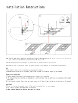
Flue cover and collar removal, Top Vented
replace.
Flue cover and collar installation, Rear Vented
replace.
Section 3-1: CONVERTING TO REAR VENT
Use the following instructions to convert an for Rear Vent use:
1. Remove the Rear ue cover and gasket (5" and 8") on the ue
outlet, as shown in Figure 8.
2. Next, Remove the Top ue collar's (5" and 8") on the ue outlet,
as shown in Figure 8.
3. Install the (removed) Rear ue cover and gasket material, to the
Top vent outlet. Fasten the cover with included hardware, as
illustrated Figure 8a.
4. Install the (5" and 8") collars to the rear vent outlet using the
included hardware, as illustrated Figure 8a.
5” Inner Flue Collar
8” Outer Flue Collar
Flue Gasket
Flue Cover Plate
Flue Gasket
Flue Cover Plate
8” Outer Flue Collar
5” Inner Flue Collar
Montigo supplies a variety of direct venting and termination options.
It should also be
selected such that it provides the shortest vent run possible. Should it
be impossible to ensure that the termination is the highest point or to
meet the venting guidelines laid out below please contact your Montigo
dealer to discuss power venting options.
NOTES FOR PLANNING VENTING:
Top vent.

P38DF* Indoor Gas Fireplace
XG0193 -103111.1
Installation
. Top vent, Roof mounted termination with no offset in vent run.
Top vent, Roof mounted with 1 offset (1 offset= two 90°
bends).
Top vent, Roof mounted with 2 offsets (1 offset= two 90°
bends).
The following details are some possible congurations for Roof mounted
terminations.
Support ring
Support plate
Firestop
32’ max.
2’ min.
PVTK1
Termination
Support ring
Support plate
Firestop
32’ max.
2’ min.
Obstacle
PVTK1
Termination
Support straps or
support plate & ring
2’ min.
Firestop
Firestop
2’
Firestop
3
2’ max
Support plate
& ring
Obstacle
PVTK1
Termination
The maximum termination point is 32’ above the replace (NOTE:
if the maximum termination height is used, the ame pattern
may be affected).
The Vertical termination must be a minimum 2’ higher than where
the termination exits the roong materials, (asphalt shingles,
cedar shakes, etc). This distance should be measured from the
high side of the roof slope where the ue ashing intersects the
roong materials. (see Figures 9 to 9c).
Termination location must be a minimum 6’ from a mechanical
air inlet.
Termination location must be a minimum 18” from a parapet wall.
For a more detailed diagram of allowed termination locations,
see .
A maximum of two offsets (each offset is made up of 2-90°
bends) may be made.
Firestops must be installed as required by National & local codes
Ensure all runs are supported with a minimum of 3 supports
per 10’ of venting.
Install all roof ashing and storm collars as shown.

P38DF* Indoor Gas Fireplace
XG0193 - 103111.1
Installation
Rear vent, Roof mounted venting (1 = 90° bend).
Support ring
Support plate
32’ max
Termination
12”
Max.
PVTK1
PEXT Sections

P38DF* Indoor Gas Fireplace
XG0193 -103111.1
Installation
1
12”
2”
1
2”
12”
Section 3-3: INSTALLING A WALL MOUNTED
DIRECT VENT TERMINATION
1). Installation of Termination with built in frame
A Termination with a Built-In Frame is installed during framing of a structure.
1. Frame the termination opening to 11" x 11".
2. Install exterior sheathing to the structure framing.
3. Fasten the termination to the sheathing using a minimum of 4 screws.
MSR Frame
PTO-4 (5"/8")
Termination
PTO-4F (5"/8")
Termination
Installing a PTO4-F termination.
Installing a PTO termination with the MSR frame.
Installing the VSS Vinyl Shield.
5). Installation of a termination shield for Vinyl Siding
The VSS Termination shield is installed when the exterior of a structure
is clad with Vinyl siding. It is placed directly above, and on-center with
the termination.
2). Installation of termination frame at time of framing
Terminations with a MSR frame allow the installation of the frame prior
to installation of the termination.
1. Frame the termination opening to 12" x 12".
2. Secure the MSR Frame to the exterior sheathing of the structure.
3. Fasten the termination to the MSR Frame using a minimum of 4 screws.
Figure 9b. Installing a PTO termination with the BSR frame.
3). Installation of termination frame at time of framing in Masonry
Terminations with a BSR frame allow the installation of the frame in
masonry prior to the installation of the termination
1. Frame the BSR opening to 12" x 12".
2. Secure the BSR Frame to the exterior sheathing of the structure.
3. Fasten the termination to the BSR Frame using a minimum of 4 screws.
1. Frame the MOSR opening to 12" x 12".
2. Fasten the MOSR frame to the interior side of the studs, concrete,
or nished wall construction using a minimum of 4 screws.
3. Insert the termination into the MOSR frame as shown here, (from
the inside) and attach to the MOSR by installing a min. quantity of
4 bolts into the threaded nuts on the MOSR Frame.
4). Installation of termination from inside structure
A Termination with a MOSR Frame is installed from the inside of the
structure. These are commonly used in high-rise construction.
MOSR Frame
PTO-4 (5"/8")
Termination
Installing a PTO termination with MOSR frame.
BSR Frame
PTKOG (5"/8")
Installing Heat Guards over Terminations is recommended in installations
where the termination is located within 7' feet above grade, or above
a pedestrian walkway, and may be Required by code in Public areas.
1. Ensure that the two longmounting brackets are facing the bottom
of the termination. (See inset). This will provide more heat protection
at the top of the termination, where temperatures are highest.
2. Attach to the faceplate of the termination using four sheet metal
screws.
Installing a PTO termination heat guard.
1
1”
11”
Framing
Exterior
Sheathing
Fastening Hardware,
minimum 4-screws
Framing
Exterior
Sheathing
Fastening Hardware,
minimum 4-screws
PTO-4 (5"/8")
Termination
Framing
Exterior
Sheathing
Fastening Hardware,
minimum 4-screws
12”
12”
Fastening Hardware,
minimum 4-screws
Framing, con-
crete or other
materials
Exterior Sheath-
ing, concrete or
other materials
Exterior Vinyl
siding
PTO-4 (5"/8")
Termination
VSS Vinyl shield

P38DF* Indoor Gas Fireplace
XG0193 - 103111.1
Installation
Measure the vertical height from the replace hearth to the centre of
the termination and the horizontal run from the replace ue collar to
the wall ange of the termination. Plot on the Venting Graph Figure 12
or 12a with an 'X'.
If the 'X' falls on or above the top boundary of the shaded area, the
installation is acceptable.
If the vertical dimension from the hearth is 120" and the horizontal
run to the wall ange of the vent termination is 144", this would be
an acceptable installation.
If the vertical dimension from the hearth is 36" and the horizontal
run to the wall ange of the vent termination is 84",
If the vertical dimension from the oor of the replace is 60" and
the horizontal run to the wall ange of the vent termination is 144",
Top Vented, wall mounted installation with one 90° bend.
The vent run must comply with Venting Graph for Top vent, wall
mounted terminations, Figure 12 or 12a.
Top Vented, wall mounted Multi-elbow installation. See
Venting Graph for Top vent, wall mounted terminations, Figure 12 or 12a.
Vent terminations must not be recessed in walls or siding.
For Heat Shield requirements see on .
Once the proposed venting layout has been determined refer to
Figure 12, 12a, 15, or 15a to ensure the layout is acceptable.
TOP VENT
All measurements for vertical or horizontal runs are measured
from center of the vent pipe.
Venting runs must fall within the limits set by the venting graph,
see Figure 12 or 12a.
The following details are some possible congurations for Wall mounted
terminations. See below.
P38DF* LP Top Vent Venting Graph for wall mounted
terminations.
P38DF* NG Top Vent Venting Graph for wall mounted terminations.
WARNING:
An inspection of the explosion relief appers and door be
made prior to lighting the replace. A faulty seal on the door gasket ...
and/or explosion ports will result in products of combustion leaking
into the living space and may result in carbon monoxide poisoning.
Heat
Shield
Termination
Hearth
Exterior
Wall
39" Min. (NG)
44" Max. (NG)
Flex section
63" Min. (LP)
16" Max. (LP)
Solid Section
Flex Section
Hearth
30”min
15’Max.
Heat
Shield
Termination
Exterior
Wall
8' MIN AT MAX
Horizontal
44
”
39”
A
C
B
Unacceptable vent run
within shaded area.
Acceptable vent run
within non-shaded area.
If your installation does not fall
within the venting parameters,
please contact a local Montigo
dealer for Power Venting options.
16
”
63”
A
C
B
Unacceptable vent run
within shaded area.
Acceptable vent run
within non-shaded area.
If your installation does not fall
within the venting parameters,
please contact a local Montigo
dealer for Power Venting options.

P38DF* Indoor Gas Fireplace
XG0193 -103111.1
Installation
Corner (Rigid) installation. (NG Models Only)
Corner (Flex) installation. (NG Models Only)
Attach an PEL-45 (45° elbow) directly onto the ue collar. Cut the PXT-
20 to suit, and attach it to the PEL-45. Slide the replace into position
and attach to the termination.
Use a PTO-4 termination and an PFL-1 or PFL-2 (12" or 24"
compressed length) and a frame, if appropriate.Flex may be turned
to obtain desired degree of angle required but must not exceed 45°.
The Kit includes a heat
shield, a PFL-18 (f/f) exible pipe, and a termination with or without
a mounting frame.
PEL-45 Elbow
PEL-90 Elbow
PXT-18
IMPORTANT:
Corner Installation is available for P38DF
. Ensure minimum
Vertical Venting Height of 40" is maintained
in corner installations.

P38DF* Indoor Gas Fireplace
XG0193 - 103111.1
Installation
Rear Vent Venting Graph for NG wall mounted terminations.
Rear Vented, wall mounted Multi-elbow termination
installation for NG or LP. Installation must comply with the Venting Graph
for Rear vent, wall mounted terminations, Figure 15 or 15a.
. Straight run, Rear Vented, wall mounted termination. Note:
Straight through the wall rear vent available for Natural Gas only.
■ All dimension lengths for vertical or horizontal runs are measured
from center of the vent pipe.
■ Venting runs must fall within the limits set by the venting graphs,
see .
■ Fireplace must be converted to Rear Vent conguration prior to
running vent, see.
Measure the vertical height from the replace hearth to the centre of
the termination and the horizontal run from the replace ue collar to
the wall ange of the termination. Plot on the Venting Graph
with an 'X'.
If the 'X' falls on or above the top boundary of the shaded area, the
installation is acceptable.
If the vertical dimension from the hearth is 120" and the horizontal
run to the wall ange of the vent termination is 138", this would be an
acceptable installation.
If the vertical dimension from the hearth is 36" and the horizontal run
to the wall ange of the vent termination is 84",
If the vertical dimension from the oor of the replace is 60" and the
horizontal run to the wall ange of the vent termination is 144",
Rear Vent Venting Graph for LP wall mounted terminations.
WARNING:
An inspection of the explosion relief appers and door
be made prior to lighting the replace. A faulty seal
on the door gasket and/or explosion ports will result in
products of combustion leaking into the living space and
may result in carbon monoxide poisoning.
26 3/8”
PXT Extension
RHS101 Heat
Shield
Termination
Hearth
Exterior
Wall
30” Max.
49” Min NG
12”
Max.
Flex or Rigid
Section
26 3/8”
63” Min LP
42
”
63”
A
C
B
Acceptable vent run
within non-shaded area.
Unacceptable vent run
within shaded area.
If your installation does not fall
within the venting parameters,
please contact a local Montigo
dealer for Power Venting options.
42
”
49”
A
C
B
Acceptable vent run
within non-shaded area.
Unacceptable vent run
within shaded area.
12
”
26.3/8”
If your installation does not fall
within the venting parameters,
please contact a local Montigo
dealer for Power Venting options.

P38DF* Indoor Gas Fireplace
XG0193 -103111.1
Installation
º
º
º
º
Connection and installation of the vent components should
adhere to the following guidelines:
Montigo recommends the use of a ex section for the nal pipe
connected directly to the replace offering greater exibility of
installation and absorption of movement.
Firestops must be installed as required by National & local codes.
Montigo recommends that all exterior corners and joints be sealed
with exterior caulking. However, we encourage you to consult
your Building Envelope Engineer or Waterproong Consultant
for further recommendations.
The following components and associated Montigo part numbers for
installation of a roof or wall mounted termination.
Use of non-Montigo parts will the warranty
and may impede operation of the replace.
Use any combination of rigid and ex pipe as required and in
any orientation (Male connectors can face in any direction).
Flex sections may be stretched up to 50% of their total length
(e.g. a 24” section maybe stretched to 36”).
Connect all vent sections using a minimum of three sheet metal
screws on the outer pipe ue.
Ensure the pipe ends male to female slide in a minimum of 1
1/2” of overlap.
Ensure all runs are supported with a minimum of 3 supports
per 10’ of venting.
When hanging/ supporting venting, ensure that 1” clearance
is maintained on sides and bottom of vent runs and 2” above
horizontal vent runs to any combustible material.
Rigid pipe may be cut less than half way from the
Ensure when cutting sections of rigid pipe to maintain integrity
of internal supports.
Place the springs, supplied with the pipe kit, between the outer
and inner pipes to keep the pipes separate and avoid any
possible hot spots.

P38DF* Indoor Gas Fireplace
XG0193 - 103111.1
Installation
Section 3-3-3: Heat Shields
The RHS8 Heat shield be used when the Termination is
() from the replace, or directly
off the rear of the replace, as shown gure 17a. The RHS101 Heat
Shield (Figure 18c and 18d) be used within the noted dimensions.
To install the RHS8, frame an opening in combustible construction,
Figure 17 below. Slide the Heat shield in place over the vent pipe
which attaches to the replace. After the replace and vent pipe has
been installed, clearances should match the dimensions in Figure 17a.
The RHS101 Heat shield be used where the RHS8 Termination
(Figure 17 and 17a) be used. Use the RHS101 where any
of the dimensions are within the parameters shown, gure 17a.
To install the RHS101, Slide the Inner Section over the vent pipe that
will connect to the replace. Then fasten the vent pipe to the back of the
replace with a minimum of three sheet metal screws. From the outside
slide the RHS101 outer section on see Figure 18. To complete the
installation fasten the Heat Shield Outer Section & Termination frame
to the structure Figure 18a.
RHS8 Installation. (Install by sliding over vent pipe where it passes
through the combustible construction).
RHS101 Installation. (Install by sliding Outer Section over vent pipe
where it passes through the combustible construction.
RHS8 Installation. (Minimum requirements).
RHS8 Heat Shield
1” Min. Both sides Typical
1” Min.
1” Min.
Combustible Framing
. RHS101 Installation.
Outer Shield 10 1/4”
3/8” Min. Both sides Typical
3/8” Min.
3/8” Min
.
Combustible Framing
12” x 12”
Inner Shield 9 3/8”
RHS101 Heat Shield after sliding the outer section in place.
Termination
Drywall / sheetrock
RHS101 Heat Shield, inner Section
RHS101 Heat Shield
Outer Section
Combustible
framing
Termination
Drywall / sheetrock
RHS101 Heat Shield, inner Section
RHS101 Heat Shield
Outer Section
Vent pipe, from fireplace
RHS8 Heat
Shield
36” Min
60” Min.
PTO Termination

P38DF* Indoor Gas Fireplace
XG0193 -103111.1
Installation
5
1
2
"
7
8
"
6 5/8
2
1
2
"
Section 4: Wiring
NOTE: If any of the original wire supplied with the appliance is replaced,
it must be replaced with the same type, or its equivalent.
Electrical connection access.
Wiring diagram for P38DF with SIT Proame Electronic Ignition
REMOTE
Receiver 14
Pin Connector
Pilot
(CPI / IPI MODE
MOTOR
IPI/CPI
RECEIVER
SPLIT FLOW
ON / OFF
TH
TPTH
DC SUPPLY
GROUND
885 Valve
Orange
Green
Chassis
connection
Remote control
Not Used)
Battery
Holder
4 x 1.5V
AA Type
120 Vac INPUT
7.5V DC
Output
Receiver 14
Battery Holder
w/ Switch
ON/REMONTE/OFF
(Not Used)
Receiver 14
Battery Holder
Top View
AC
Adapter
Green
Blk
Wht
Blk
Blk
Blk
Blk
Wht
Wht
Thermo
Sensor
Fan
Fan
Fan
Receptacle
Wht
Blk
Bulbs
Blk
Wht
Control Valve
Receptacle
Green
Green
Blk
Wht
Fan Speed
Control
Wht
Blk
L2
L1
Ground
Red
White
Green
Red
Black
WALL SWITCH
1
6
1
6
Power Supply
110VAC, 5amp

P38DF* Indoor Gas Fireplace
XG0193 - 103111.1
Installation
Section 5-1: FUEL CONVERSION
n Verify that your replace is compatible with your available
gas type. (Natural Gas or Propane shown by "N" or "L"
in your model number
n If gas type is not compatible, contact your local Montigo
representative to purchase a conversion kit.
n Conversion kits must be installed by a qualied service
technician.
Section 5-2: GAS PRESSURE
n Optimum appliance performance requires proper input
pressures.
n Gas line sizing requirements will be determined in ANSI
Z223.1/ NFPA 54 National Fuel Gas Code in the USA
and CAN/CGA B149.1 in Canada.
Pressure requirements are:
n The manifold outlet pressure is set from the factory to
the appropriate pressure but should be veried.
n To check pressures, control valves have a provision to
remove a 1/8” N.PT. plug to be tted with a hose barb.
n Montigo requires a service shut off valve be located in
an accessible location to isolate the gas supply.
Qn QOnly install gas shut-off valves approved for use by the
state, province, or other governing body in which the
replace is being installed.
Section 5-3: GAS CONNECTION
n See Figure 21 for location of gas line access.
n Flexible gas connectors must not exceed 3 feet in length,
unless allowable within local regulations.
n Connect incoming gas line to the 1/2"or 3/8" gas inlet port.
n Purge all air out of gas line.
n Check appliance connection, valve and valve train under
normal operating pressure with a commercially available
leak check solution.
1
1
4
"
2"
8 1/2
Section 5: Installing the Gas Line
Gas line access.
When pressure testing the fireplace, Gas line, and input system follow the appropriate
local codes or your area. DO NOT connect the fireplace to pressures in excess of
1/2lb. This will damage the gas control valve.
NOTICE

P38DF* Indoor Gas Fireplace
XG0193 -103111.1
Installation
Section 6: Finishing
Horizontal Run
(
in.
)
Vertical Height (in.)
Combustible construction
allowed in shaded area
Combustible facing material
Combustible header
Non-combustible header
Top of fireplace
Non-combustible facing
Combustible mantels and facings.
WARNING!
When covering the upper metal portion of the replace, up to 4" (as
shown, Fig.22) with a non-combustible material : The
decorative facing materials may be subject to temperatures in excess
of 250° F. This should be considered when selecting facing materials.
Non-combustible mantels and mouldings may be safely installed over
the top and on the front of the replace provided that they do not project
beyond shaded area shown in
When sizing the nish material for your replace, it is important to
remember the following: THE OPENING MUST NOT BE OBSTRUCTED
IN ANY WAY - to do so restricts the air supply for the control compartments
and heat exchanger it also prevents access for servicing controls.
The face of the replace may be painted to match the room decor,
provided you use a heat-resistant paint. Decorative facing must not
extend past the replace opening at all, because it will interfere with
the access to retainers for removal of glass door.
Glass doors on gas fireplaces are extremely hot while the fireplace is on and
remain hot even after the fireplace has been turned off. Safety screens are
available and can reduce the risks of severe burns. Please keep children away
from the fireplace at all times.
CAUTION
Do not use ammonia based or abrasive cleaners on the glass, they will permanently
etch the surface. Use an approved gas fireplace glass cleaner such as Kel-Kem or
White off.
NOTICE
4”Non-Combustibl
e
Fa
cing Material
Non-combustible Heade
r
Drywall/
Sheetrock
4”
3”
Combustible surrounds.
We recommend careful consideration be given to the effects of elevated mantel
temperatures which may be in excess of product design, for example: candles, plastic
or pictures. This can cause melting, deformation, discoloration or premature failure of
T.V. radio, and other electronic components.
CAUTION
Mantels & Surrounds
National Canadian Gas Association mantel test requirements
are for re hazard prevention to combustible materials.
New technology, to meet consumer and government demands for the
wise use of energy, has prompted us to manufacture many models of
replaces which are hot, fuel and energy efcient.
Please be aware; temperatures over the mantel will rise above normal
room temperature and walls above replace may be hot to touch.
Side wall clearances are 3". Combustible surrounds may be installed
with 3" clearance to the side of the replace as shown in .

P38DF* Indoor Gas Fireplace
XG0193 - 103111.1
Installation
Section 7: Installing & Removing the Door
Removing the door:
The doors are removed in a few simple steps. Follow these
instructions below to remove the Horizontal access panel, unlatch the
door buckles and, remove the door. Replace in reverse order.
Locate the door buckles.
Removing and installing the Horizontal Access Panel
Locate the Door Buckles:
Remove the Horizontal cover
by placing ngers in both nger
holes, then pushing away from
you and lifting out. Place it aside
during maintenance or cleaning.
Install in reverse order.
To install the door, hook the top edge of the door frame into place. Lower
the door into position and follow the previous steps shown in reverse order.
Installing the Door:
2
Ensure the tool is rmly in
the lower end of the slot,
(as shown), Then pull toward
you (Caution: hold the tool
securely).
3
Pull hard if necessary to
release the spring tension.
(Caution: The latch springs
back with force, hold the tool
securely).
4
Remove the tool from the
latch slot. Ensure the latches
are hanging freely, the hook
end is released from the
bottom of the door. (Repeat
all 4-steps for the remaining
latches).
Step 8:
Grasp the Door on either side, usually midway and lift upward, lift
the door carefully up and away from the front of the replace. See
Figures 24g. Place the Door aside in a safe place while maintenance
and / or cleaning is being performed.
Removing and installing the glass doors.
Removing the Door:
Door Latch Hook
Door Latch Slot
Hand-hold
. Door buckle Tool
1
Step 4:
Firmly grasp hand-hold
end of Door buckle tool
and place the machined
end in the slot under door
frame. (as shown)
Finger Holes
Installed Gas
Valve Cove
r
/