
6
Submersible sewage and
drainage pumps
GX 40, GM 50
OPERATING INSTRUCTIONS
1. Pump designation
See designation on the pump name-plate or on
the bar-code label.
Meaning of the designations:
GX 40 = Stainless steel pump with G 1
1
/
2
ISO 228 (DN 40) delivery connection.
GM 50 = Cast iron pump with G 2 ISO 228
(DN 50) delivery connection.
GM 50-65= Cast iron pump with (DN 65)
flanged delivery connection.
C = With two- (GXC) or single-passage
(GMC) impeller.
V = With free-flow (vortex) impeller.
M = With single-phase motor (without
indication = with three-phase motor).
2. Operating conditions
Standard construction
- For clean and dirty water, also containing solids
with maximum size:
35 mm for GX 40;
45 mm for GMC ..; 50 mm for GMV ....
With a high solid content or with filamentous par
ticles use only the free-flow (vortex) GXV and
GMV construction.
-
Maximum liquid temperature: 35 °C.
- Maximum liquid density: 1100 kg/m
3
.
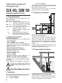
- Minimum dimensions of installation pit:
0.55x0.55m; depth 0.5 m.
- Minimum immersion depth:
250 mm for GX 40;
180 mm for GM 50.
- Maximum submersion depth: GX 40 = 5 m;
GM 50 = 10 m (with suitable cable length).
-
Maximum starts/hour: 30 at regular intervals.
Sound pressure at minimum immersion depth:
< 70 dB (A).
Noise disappears when the pump is submersed.
Do not use in garden ponds, tanks or
swimming pools when people are in the
water.
The Pump cannot be used in
explosive or flammable environments.
3. Installation
The internal diameter of the delivery pipe must never be
smaller than the diameter of the pump connection port:
G 1
1
/
2
(DN 40) for GX 40;
G 2 (DN 50) for GM 50;
(DN 65) for GM 50-65.
The pump must be lifted and transported using
the handle fitted for this purpose and not pulled
by the electrical power cable.
Place the pump, with vertical axis, at the bottom
of the pit or at the site of installation.
3.1. Stationary installation
For stationary installation fit a check valve against
back flow in the delivery pipe.
Provide for the possibility of removing the pump
without having to drain the entire system (if
necessary, fit a gate valve and a union coupling).
With the pump in the resting position secure the
delivery pipe to a rest, suitable for its length and
weight.
If slime deposits are expected to form at the
bottom of the installation pit, a support must be
provided to keep the pump raised.
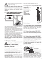
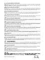
3.2. Transportable installation
A safety rope or chain of non-perishable material
should always be used to secure the pump.
When a plastic or flexible delivery pipe is used,
the safety rope or chain should be utilized for
lowering, securing and raising the pump.
3.93.037/3
3.93.037/3
GX = 250
G
M
= 180
GX = 450
G
M
= 500
3.93.037/3
3.93.037/3
GX = 250
G
M
= 180
GX = 450
G
M
= 500
On
Off

7
Never use the electric power cable to
suspend the pump.
Attach the power supply cable to the delivery pipe
or to the safety rope with cable clamps.
The
power cable should not be taut: allow for a certain
degree of slackness to avoid the risk of strain
caused by expansion of the pipe during
operation.
3.3. Fixed installation with automatic
coupling feet and guide rails.
The automatic coupling system allows for quick
and efficient inspection operations.
The coupling foot is fastened to the bottom of the
sump together with the delivery pipe; two guiding
tubes connect it to the anchoring bracket secured
to the edge of the sump cover.
The pump is lowered along the guiding tubes until
it reaches the exact coupling position; the seal
will be tight thanks to the weight of the pump.
This operation can be repeated any number of
times and it makes checking and inspection
operations easier; the pump is simply extracted
from the sump by means of a chain (even if the
system is flooded).
4. Electrical connection
Electrical connection must be carried
out only by a qualified electrician in
accordance with local regulations.
Follow all safety standards.
The unit must be always earthed, also with a
non-metallic delivery pipe.
Make sure the frequency and mains voltage
correspond with the name plate data.
For use in swimming pools (not when persons are
in the pool), garden ponds and similar places, a
residual current device with I∆N not exceeding
30 mA
must be installed in the supply circuit.
Install a device for disconnection from the
mains (switch) with a contact separation of at
least 3 mm on all poles.
When extension cables are used, make sure the
cable wires are of adequate size to avoid voltage
drops and that the connection stays dry
.
4.1. Single-phase pumps GXCM, GXVM
Supplied with
incorporated thermal
protector, with
power cable type
H07 RN8-F, 4G1 mm
2
and with float
switch.
Control box with
capacitor supplied
on request.
Electrical diagram
4.2. Single-phase pumps GMCM, GMVM
Supplied with incorporated capacitor and thermal
protector, with power cable type H07 RN8-F,
3G1.5 mm
2
with plug and float switch.
4.3. Three-phase pumps GXC, GXV
Install in the control box an overload-protective
device in accordance with the name-plate current.
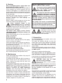
4.4. Three-phase pumps GMC, GMV
Fitted with 2
thermal pro
tectors
which are connected
in series and inserted between two different phases.
The
thermal pro
tectors
, in the three-phase motors,
provide protection against overloading and not
against operation with a blocked rotor.
The control box must therefore also be fitted with
a suitable hot-wire ammeter relay cuopled with
the control contactor.
Follow the electrical circuit diagram indicated below
With three-phase pumps, when the water level is
not under direct visible control, install a float
switch connected to the control box to protect the
pump against dry running and to set the water
levels to stop and automatically start the pump.
green/yellow
black
blue
maroon
grey
grey
Motor
3 ~ 220-240 V
3 ~ 380-415 V
To the terminal connection
points of the contactor
Thermal pro
tectors
to connect to the
contator coil
4.93.002/2
M
1
black
grey (blue)
maroon
green/yellow
4.93.002/3

8
5. Starting
With a three-phase power supply make sure
the direction of rotation is correct.
Before installation, momentarily start the motor to
check through the suction opening that the
rotation of the impeller is as shown by the arrow
on the pump. Otherwise disconnect electrical
power and reverse the connections of two phases
in the control box.
Operation with wrong direction of rotation will
cause vibration and loss of delivery capacity
.
Reverse rotation can also demage the
mechanical seal.
When in doubt, take the pump out of the water
and check rotation of the impeller by sight.
Never introduce fingers in the
suction opening unless it is absolutely
certain the electric power has been
disconnected (that the pump cannot be
accidentally switched on) and the impeller has
stopped rotating completely
.
The motors with supply current directly
switched by thermally sensitive switches can
start automatically
.
Never take the pump out of the water while the
pump is still operating.
Avoid running dry.
Construction with float switch:
the float switch, connected directly to the pump,
controls starting and stopping.
Check that the float switch is free from any obstacle.
If necessary, adjust the float-switch cable (secure
the length with screw 96.09).
Execessive cable length may cause the motor to
overheat and the pump to run dry.
Construction without float switch:
start the pump only if immersed at least 250 mm (GX
40) or 180 mm (GM 50) in the liquid to be raised.
6. Maintenance
Under normal operating conditions the pump will
not require maintenance.
If freezing may be expected while the pump re-
mains inactive and it is not submersed at a safe
depth, remove the pump from the water and
leave in a dry place.
If the pump is temporarily used with incrusting
liquids (prone to crystallization or liquids with
particles that solidify when exposed to air in
stagnant conditions) or water containing
chloride, flush the pump briefly with water
immediately after use to remove any deposit.
If the pump has not been used for a long time and
does not start or gives no water (but electrical
connections are in order), the pump must be
removed from the water and checked to see if it is
choked by any foreign matter or blocked by
sediment, deposits or any other cause.
INSTRUCTIONSFOR SAFETY, HYGIENE AND
HEALTH PROTECTION AT WORK.
Disconnect electrical power before
any servicing operation and make
sure the pump cannot be
accidentally switched on.
The pump may have been immersed
in hazardous substances or products
emanating toxic gases, or may be
located in an environment which is
toxic due to other reasons; make sure all
necessary precautionary measures are taken
to avoid accidents.
Any pumps that require inspection/repair
must be drained and carefully cleaned inside
and outside before dispatch/submission.
Hose down all accessible parts with a jet of water.
In order to avoid the risk of
mechanical or electrical injury
all portable pumps should be
securely isolated from electrical
power supply prior to their relocation.
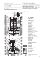
7. Dismantling
For disassembly and reassembly, refer to the
cross-section drawing.
To inspect the impeller (28.00), to clean the
internal parts and to check whether the impeller
turns freely when moved by hand, remove the
nuts (GX) or the screws (GM) (12.20) and casing
cover (12.00).
To dismantle the impeller remove the nut (28.04).
Use the threaded dismantling holes to remove
the GMV impeller.
Others parts should not be dismantled.
The pump function can be impaired by erro-
neous procedure or tampering with internal parts.
If the mechanical seal (36.00) and the oil chamber
are to be inspected, follow these instructions.
CAUTION: there may be slight
pressure in the oil chamber.
Care must be taken to avoid a sudden
spurting of oil.
Once the plug (14.46) with washer (14.47) have
been removed, adjust the hole to the downward
position and empty the chamber completely.
Do not dispose of the waste oil in the
enviroment.
The mechanical seal (36.00) can be inspected by
removing the impeller key (28.20), the screws
(14.24) and the pump casing (14.00).
When re-filling with fresh oil, remember that the
chamber must not be completely filled; a
suf
ficient quantity of air must remain inside it in
order to compensate for overpressure caused by

9
Cross section drawings
Nr. Designation
12.00 Casing cover
12.20
Screw
12.21 Nut
14.00 Pump casing
14.20 Casing gasket
14.22 Fastening ring
14.24 Screw
14.46 Plug
14.47 Gasket
28.00 Impeller
28.04 Impeller nut
28.08 Washer
28.20 Key
36.00 Mechanical seal
40.00 Radial shaft seal
64.08 Shaft sleeve
64.12 O-ring
70.00 Motor cover, pump side
70.05 O-ring
70.11 Cable gland ring (float switch)
70.12 Cable gland ring
70.13 Washer
73.00 Pump side bearing
73.08 V-Ring
76.00 Motor casing with winding
76.01 Motor jacket with winding (1)
76.02 Kit, motor jacket
76.04 Cable gland
76.60 Float switch
76.62 Jacket cover
76.63 Screw
76.64 Handle
76.65 Handle clamp
76.66 Washer
78.00 Shaft with rotor packet
78.12 O-ring
81.00 Bearing
82.01 Motor end-shield, non-drive end (1)
82.02 Screw
82.03 O-ring
82.04 Compensating spring
82.05 Screw (1)
94.00 Capacitor
94.04 Capacitor collar
96.00 Cable
96.07 Cable fastener
96.08 Clamp
96.09 Screw
96.10 Nut
(1) Cannot be supplied separately
(2) Oil
(3) Grease
thermic dilation of the oil.
The quantity of oil to be inserted in the chamber is:
0.2 litres for GX 40;
0.5 litres for GM 50.
Use white oil suitable for food machinery and
pharmaceutic use.
For the GM 50 pumps a normal engine oil of the
SAE 10W
-30 type can also be used.
8. Queries and spare parts
In your queries and orders please mention the
pump name-plate data. Alternatively, if the bar-code
label has been saved, mention the numbers on the
label or enclose a photocopy of it.
When ordering spare parts quote part
designations and drawing position numbers.
Changes reserved.
3.94.024.1
(1)
(2)
GMC
GMV 50-65
GMC 50-65
GMV
76.64
64.08
36.00
14.00
28.00
28.20
28.08
28.04
64.12
76.63
82.03
82.02
82.04
81.00
78.00
73.00
14.46
14.47
14.22
14.24
14.20
28.00
12.00
96.07
96.09
96.10
96.08
76.63
40.00
76.60
76.62
76.04
96.00
70.12
70.13
70.05
76.65
12.21
70.00
76.01
82.01
82.05
78.12
76.02
70.11
76.66
73.08
GXV
GXC
3.94.035
(1)
(1)
(2)
(3)
(1)
4.94.061
96.08
76.04
96.00
73.00
36.00
70.00
14.20
14.46
28.00
28.20
76.60
12.20
76.64
82.04
81.00
78.00
76.00
94.12
94.04
94.00
14.24
14.00
28.00
28.04
12.00
96.09

DICHIARAZIONE DI CONFORMITÀ
Noi CALPEDA S.p.A. dichiariamo sotto la nostra esclusiva responsabilità che le Pompe
GXC, GXCM, GXV, GXVM, GMC,
GMCM, GMV, GMVM
, tipo e numero di serie riportati in targa, sono conformi a quanto prescritto dalle Direttive
2004/108/CE, 2006/42/CE, 2006/95/CE e dalle relative norme armonizzate.
We CALPEDA S.p.A. declare that our Pumps
GXC, GXCM, GXV, GXVM, GMC, GMCM, GMV, GMVM,
with pump type
and serial number as shown on the name plate, are constructed in accordance with Directives 2004/108/EC,
2006/42/EC, 2006/95/EC and assume full responsability for conformity with the standards laid down therein.
DECLARATION OF CONFORMITY
I
GB
Wir, das Unternehmen CALPEDA S.p.A., erklären hiermit verbindlich, daß die Pumpen
GXC, GXCM, GXV, GXVM, GMC, GMCM, GMV, GMVM
,
Typbezeichnung und Fabrik-Nr. nach Leistungsschild den EG-Vorschriften 2004/108/EG, 2006/42/EG, 2006/95/EG entsprechen.
KONFORMITÄTSERKLÄRUNG
DECLARATION DE CONFORMITE
Nous, CALPEDA S.p.A., déclarons que les Pompes GXC, GXCM, GXV, GXVM, GMC, GMCM, GMV, GMVM, modèle et numero
de série marqués sur la plaque signalétique sont conformes aux Directives 2004/108/CE, 2006/42/CE, 2006/95/CE.
DECLARACION DE CONFORMIDAD
En CALPEDA S.p.A. declaramos bajo nuestra exclusiva responsabilidad que las Bombas
GXC, GXCM, GXV, GXVM,
GMC, GMCM, GMV, GMVM,
modelo y numero de serie marcados en la placa de caracteristicas son conformes a las di-
sposiciones de las Directivas 2004/108/CE, 2006/42/CE, 2006/95/CE.
OVERENSSTEMMELSESERKLÆRING
Vi CALPEDA S.p.A. erklærer hermed at vore pumper
GXC, GXCM, GXV, GXVM, GMC, GMCM, GMV, GMVM,
pumpe type
og serie nummer vist på typeskiltet er fremstillet i overensstemmelse med bestemmelserne i Direktiv 2004/108/EC,
2006/42/EC, 2006/95/EC og er i overensstemmelse med de heri indeholdte standarder.
D
F
E
DK
CALPEDA S.p.A. intygar att pumpar
GXC, GXCM, GXV, GXVM, GMC, GMCM, GMV, GMVM,
pumptyp och serienummer,
visade på namnplåten är konstruerade enligt direktiv
2004/108/EC, 2006/42/EC, 2006/95/EC. Calpeda
åtar sig fullt ansvar
för överensstämmelse med standard som fastställts i dessa avtal.
DECLARAÇÃO DE CONFORMIDADE
Nós, CALPEDA S.p.A., declaramos que as nossas Bombas
GXC, GXCM, GXV, GXVM, GMC, GMCM, GMV, GMVM,
modelo
e número de série indicado na placa identificadora são construìdas de acordo com as Directivas 2004/108/CE,
2006/42/CE, 2006/95/CE e somos inteiramente responsáveis pela conformidade das respectivas normas.
CONFORMITEITSVERKLARING
Wij CALPEDA S.p.A. verklaren hiermede dat onze pompen GXC, GXCM, GXV, GXVM, GMC, GMCM, GMV, GMVM, pomptype
en serienummer zoals vermeld op de typeplaat aan de EG-voorschriften 2004/108/EU, 2006/42/EU, 2006/95/EU voldoen.
VAKUUTUS
Me CALPEDA S.p.A. vakuutamme että pumppumme
GXC, GXCM, GXV, GXVM, GMC, GMCM, GMV, GMVM,
malli ja
valmistusnumero tyyppikilvcstä, ovat valmistettu
2004/108/EU, 2006/42/EU, 2006/95/EU
direktiivien mukaisesti ja
CALPEDA ottaa täyden vastuun siitä, että tuotteet vastaavat näitä standardeja.
EU NORM CERTIFIKAT
P
NL
SF
S
TR
Bizler CALPEDA S.p.A. firması olarak
GXC, GXCM, GXV, GXVM, GMC, GMCM, GMV, GMVM,
Pompalarımızın, 2004/108/EC, 2006/42/EC,
2006/95/EC
, direktiflerine uygun olarak imal edildiklerini beyan eder ve bu standartlara uygunlug˘una dair tüm sorumlulug˘u üstleniriz.
UYGUNLUK BEYANI
Montorso Vicentino, 01.2010
Il Presidente
Licia Mettifogo
Åìåßò ùò CALPEDA S.p.A. äçëþíïõìå üôé ïé áíôëßåò ìáò áõôÝò GXC, GXCM, GXV, GXVM, GMC, GMCM, GMV, GMVM, ìå ôýðï êáé áñéèìü
óåéñÜò êáôáóêåõÞò üðïõ áíáãñÜöåôå óôçí ðéíáêßäá ôçò áíôëßáò, êáôáóêåõÜæïíôáé óýìöùíá ìå ôéò ïäçãßåò 2004/108/EOK, 2006/42/EOK,
2006/95/EOK, êáé áíáëáìâÜíïõìå ðëÞñç õðåõèõíüôçôá ãéá óõìöùíßá (óõììüñöùóç), ìå ôá óôÜíôáñò ôùí ðñïäéáãñáöþí áõôþí.
GR
Ä
Ä
Ç
Ç
Ë
Ë
Ù
Ù
Ó
Ó
Ç
Ç
Ó
Ó
Õ
Õ
Ì
Ì
Ö
Ö
Ù
Ù
Í
Í
É
É
Á
Á
Ó
Ó
RU
îìïàíèß “Calpeda S.p.A.” çàßâëßåò ñ ïîëíîé îòâåòñòâåííîñòüþ, ÷òî íàñîñû ñåðèé
GXC, GXCM, GXV, GXVM,
GMC, GMCM, GMV, GMVM
, òèï è ñåðèéíûé íîìåð êîòîðûõ óêàçûâàåòñß íà çàâîäñêîé òàáëè÷êå ñîîòâåòñòâóþò
òðåáîâàíèßì íîðìàòèâîâ 2004/108/CE, 2006/42/CE, 2006/95/CE.
åêëàðàöèß ñîîòâåòñòâèß
-
 1
1
-
 2
2
-
 3
3
-
 4
4
-
 5
5


Ask a question and I''ll find the answer in the document
Finding information in a document is now easier with AI
Related papers
Other documents
-
GREE GMV-SPK1 Multipro Single Point Power Kit User manual
-
Basement Watchdog KCV Operating instructions
-
 Elektra Beckum Submersible Well Pump TP 7000 S User manual
-
Total TWP, UTW Series Submersible Pump User guide
-
 ACPro GMV-72WM/B-FU Owner's manual
-
Vortex B Series Operating Instructions Manual
-
-
 AQUATECH ECO 22000 User Instructions
-
 Liberty Pumps LE41A Specification
-


