Page is loading ...

10x10 Trellis Pergola
ASSEMBLY GUIDE
Ver 2.2 10162020
www.wearevita.com
211 Campbell St. Sarnia,
Ontario, Canada N7T 2G6

Table of Contents
2
1
0
x10 Trellis Pergola
3
10x10 Trellis Pergola
Introduction & Overview……………………………. . . . . . . . . . . . . . . . . . . . . . . . . . . . . . . . . . . . . . . . . . . . . . . .………. . . . . .
Pergola Materials Overview………………………. . . . . . . . . . . . . . . . . . . . . . . . . . . …. . . . . . . . . . . . . . . . . . . . . . . . . . . . . . . . . . .
Pergola Materials Breakdown………………………. . . . . . . . . . . . . . . . . . . . . . . . . . . . . . . . . . . . .…. . . . . . . . . . . . . . . . . . . . . . .
Pergola Additional Materials List………………………………. . . . . . . . . . . . . . . . . . . . . . . . . . . . . . . . . . . . . . . . . . . . . . . . . .
Side Panel Trellis Assembly…………………………………. . . . . . . . . . . . . . . . . . . . . . . . . . . . . . . . . . . . . . . . . . . . . . . . . . . . . . . . . .
Corner Post Assembly………………………………………………. . . . . . . . . . . . . . . . . . . . . . . . . . . . . . . . . . . . . . . . . . . . . .
Left and Right Corner Post Assembly . . . . . . . . . . . . . . . . . . . . . . . . . . . . . . . . . . . . . . . . . . . . . . . . . . . . . . . . . . . . . . . . . . . . . . . . . . . . . .
Main Support Beam Assembly…………………………. . . . . . . . . . . . . . . . . . . . ……………………. . . . . . . . . . . . . . . .
Rafter Assembly……………………………………………………. . . . . .…. .……….……. .…………. . . . . . ….
Main Support Beams Installation…………………………. . . . . .………….……. .…………. . . . . . ….. . . . . . . . . . . .
Rafter Assembly Installation………………………………. . . . . .………….……. .…………. . . . . . ….. . . . . . . . . . . .
Shade Slat Assembly & Installation……………………………………. . . . . .………….……. .…………. . . . . . ….
Pergola Mounting……………………………………………………. . . . . .………….……. .…………. . . . . . ….
Pergola Installation on Deck (with access to under the deck)…………………………………………………
Pergola Installation on Deck (with no access to under the deck)…………………. . . . . . . . . . ………………….
Pergola Installation on Existing Concrete Pad…. . . . . . . . . . . . . . . . . . . . . . . . . . . . . . . . . . . . . . . . . . . . . . . . . . . . . . . . . . . . . . . . . . . . .
Additional Installation Note. . . . . . . . . . . . . . . . . . . . . . . . . . . . . . . . . . . . . . . . . . . . . . . . . . . . . . . . . . . . . . . . . . . . . . . . . . . . . . . . . . . . . . . . .
PAGE
4
5
6
7
8
9
10
11
12
15
17
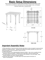
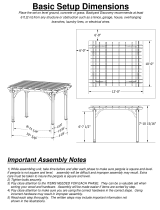
88 1/4 in
12 in
120 in
88 in
146 1/2 in
146 1/2 in
39 in
20 1/4 in
95 7/8 in
12 in
120 in
82 in
90 1/2 in
12 in
60 1/4 in
Top View
Front View
Side View
10
18
19
20
21
22

Introduction & Overview
3
10x10 Trellis Pergola
Getting Started
First off, allow us to say thank you for the investment you have made in one
of our fine pergola kits. This kit is designed to be assembled and installed
ideally by two people with basic carpentry knowledge and tools. Do not
attempt alone, especially during the installation stage. Should you decide to
moderately modify the dimensions of your pergola from the standard kit size,
a circular saw with a sharp fine-tooth blade is all that is needed to cut, shorten
or modify the vinyl components.
When assembling components place on a
non-abrasive
surface (ie: shipping box) to avoid scratching.
We recommend a 15’x15’
area for unobstructed assembling. You should not
need to use excessive force
when
assembling any components.
Planning & Preparing
Because this project is made to stand independent of your home, you can
either locate it near your house or let it stand alone in the garden. By keeping
it unattached from your home you will not have to deal with moving existing
gutters or matching eave heights. If you plan to build your pergola close to
the house, please keep the outer extremities of the pergola a minimum of 4
inches back from your eaves.
It is critical before you start that you consider the current slope of elevation
where the pergola is planned - if there is any. Also utility or sprinkler line
location is important to identify prior to excavating holes if necessary.
You should also check to verify
local building codes, ordinances, neighbour-
hood covenants, or height restrictions regarding this type of structure.
Restriction of Use
This product is not designed to carry additional
weight loads such as swings, people or other
objects.
Please take the time to read this instruction
guide thoroughly prior to the construction
of your pergola. If you have any questions,
feel free to contact our technical dept by calling
1 800 282 9346 (Mon to Fri 8:00 A.M to 5:00 P.M.
EST).

10x10 Trellis Pergola Materials Overview
4
1
0
x10 Trellis Pergola
1. Posts - Long
(8) - 11037
2. Posts - Short (4) - 11038
3. Main Support Beams (8) - 11039
4.
Rafters
(8) - 11040
5.
Rafter & Beam Decorative End Caps
(16) - 10700
6.
Rafter & Beam Joiners
(8) - 10707-1
7. Trellis Posts (16) - 11041
8. Trellis Vertical Slat (8) - 11042
9. Trellis Horizontal Rails - Middle (40) - 11043
10. Trellis Horizontal Rails - Top and Bottom (16) -
11044
11.
End Caps - 7/8” x 1 1/2“ (40) - 11047
12. Braces (8) - 11045
13. Brace Brackets (8) - 11053
14.
End Caps - 2” x 3 1/2”
(12) - 10102
15.
Shade Slat Decorative End Caps
(12) - 10998
16.
Shade Slats
(12) - 11048
17.
Shade Slat Joiners
(6) - 11049
18. Aluminium Stiffener for Beams / Rafters (8) - 10996
19. Aluminium Stiffener Inserts for Beams (8) - 10995
20.
Mounting Plates - Left
(2) - 11050
21.
Mounting Plates - Right
(2) - 11051
22.
Mounting Stakes
(12) - 11052
5
4
7
9
8
1
10
11
2
1
20
22
14
11
12
13
15 16 17
19
3
21
18
6

17
18
16
19
21
20
22
1. Posts - Long (8) - 11037 - 2” x 3 1/2“ x 94 7/8”
2. Posts - Short (4) - 11038 - 2“ x 3 1/2” x 92 5/8“
3. Main Support Beams (8) - 11039 - 1 1/2” x 4 1/2“ x 66”
4.
Rafters
(8) - 11040 - 1 1/2“ x 4 1/2” x 66“
5.
Rafter & Beam Decorative End Caps
(16) - 10700
6.
Rafter & Beam Joiners
(8) - 10707-1
7. Trellis Posts (16) - 11041 - 7/8” x 1 1/2“ x 60”
8. Trellis Vertical Slat (8) - 11042 - 1/4“ x 1 1/2” x 57 1/4“
9. Trellis Horizontal Rails - Middle (40) - 11043 - 7/8” x 1 1/2“ x 11
7/8”
10. Trellis Horizontal Rails - Top and Bottom (16) - 11044 - 7/8“ x 1
1/2”
11.
End Caps - 7/8” x 1 1/2“ (40) - 11047
12. Braces (8) - 11045 - 7/8” x 1 1/2“ x 18”
13. Brace Brackets (8) - 11053
14.
End Caps - 2” x 3 1/2”
(12) - 10102
15.
Shade Slat Decorative End Caps
(12) - 10998
16.
Shade Slats
(12) - 11048 - 7/8” x 3” x 66”
17.
Shade Slat Joiners
(6) - 11049
18. Aluminium Stiffener for Beams / Rafters (8) - 10996
19. Aluminium Stiffener Inserts for Beams (8) - 10995
20.
Mounting Plates - Left
(2) - 11050
21.
Mounting Plates - Right
(2) - 11051
22.
Mounting Stakes
(12) - 11052 - 1/2” O.D. x 18”
10x10 Trellis Pergola Materials Breakdown
Check Boxes (Total of 4) for These Contents
In the event of missing or defective parts please call our customer service
dept. at
1 800 282 9346
(Mon. to Fri. 8:00 AM to 5:00 PM EST).
1
Not to Scale
5
10x10 Trellis Pergola
11
12
13
14
15
2
6
7
3
8
4
9
5
10
x 11 7/8”

D
J
Pergola Additional Materials List
Hardware (in plastic bag)
NOTE: WE HAVE INCLUDED 10% EXTRA SCREWS BEYOND WHAT IS IDENTIFIED BELOW.
All Screws Included with this Kit are Self-Auguring.
A. Vinyl Weld Glue (2) - 20000
B.
1 1/2” Self-Auguring Stainless Steel Screws (64) - 20005
(To fasten trellis assembly to pergola posts
)
C.
1 1/2” Self-Auguring Stainless Steel Screws (24) - 20005
(For brace brackets
)
D.
1 1/2” Self-Auguring Stainless Steel Screws
(24) - 20005
(To fasten shade slats to rafters)
E.
1 1/2” Self-Auguring Stainless Steel Screws (32) - 20005
(For beam and rafter joiners)
F. 1 1/2”
Self-Auguring Stainless Steel Screws (16) - 20005
(To fasten braces to beams / rafters)
G.
1” Self-Auguring Stainless Steel Hex Head Tek Screws (24) - 20023
(To fasten posts to mounting plates)
H.
2 1/2” Self-Auguring Stainless Steel Screws (48) - 2009-1
(To fasten beams / rafters to posts)
I.
3” Self-Auguring Stainless Steel Screws (16) - 20007
(To fasten rafters to beams)
Extra Materials You will Need
We have provided mounting plates with stakes to mount your
pergola into the ground. You may, however, follow one of the
options below to better suit your need:
If Mounting Pergola onto Deck (with access to under the Deck)
J.
1/2“ Bolts with Washers and Locking Nut (12)
(purchase at local building
center).
Length of bolts will depend on thickness of decking material.
If Mounting Pergola onto Deck (with no access to under the Deck)
K.
1/2” - 5/8“ Lag Bolts (12)
(purchase at local building center)
Length of Lag bolts will depend on thickness of decking material.
If Mounting Pergola on existing Concrete Pad
L.
1/2” x 4” Sleeve Anchors (12)
(purchase at local building center)
Tools You Will Need
• Level
• Hammer
• Tape Measure
• Step Ladders (2)
• Cordless Drill
• Hex Nut Driver (5/16” or 8mm)
• 1/8” x 2” Drill Bit
(to pre-drill holes on top and bottom of joiner to penetrate aluminium inserts as necessary)
Tools You May Need
A
B
E
K
Not to Scale
6
• Circular Saw with Fine
Tooth Blade
• Framing Level
• Framing Square
• Hacksaw
(or a motorized cutting device designed to cut steel)
10x10 Trellis Pergola
Purchase Separately
Purchase Separately
I
J
C
H
F
L
Purchase Separately
G

Side Panel Trellis Assembly
7
10x10 Trellis Pergola
One by one, insert five Middle Trellis Horizontal Rails over the
Trellis vertical Slat as shown. Excess force should not be used.
Slide the End Trellis Horizontal Rails over the assembly as
shown. Note that there are only one side with a routed hole.
Starting with one end, carefully ‘walk’ the assembly into the
Trellis Post while making adjustments.
Note that the horizontal rails are tabbed; once inserted, the
horizontal rails will lock into place.
Starting with one end, carefully ‘walk’ a Trellis Post over the
assembly as shown.
Pressure fit four end caps as shown.
Repeat for other 7 side panel trellisses.
1
2
4
STEP ONE
5
6
3
Pergola Assembly
1
2
3
5
4
6
x 8

8
10x10 Trellis Pergola
Corner Post Assembly
Lay all the LONG POSTS on its side as shown and create a mark
12 inches from the end.
Place one of the trellis assembly from the previous step on the
narrow side of the long post and align the one end to the
pencil mark.
Fasten the trellis assembly to the post while ensuring that it is straight
and level using four 1-1/2” screws through the pre-drilled holes.
Using a helper, place the assembly onto another long post on its
narrow side.
Fasten the trellis assembly to the post using four 1-1/2” screws
through the pre-drilled holes.
Repeat this for a total of 4 panels.
1
2
4
STEP TWO
3
Pergola Assembly
1
2
4
3
12 in
Align to pencil mark
5
5
Align to pencil mark
6

Level
Left and Right Corner Post Assembly
There are Left and Right corner assemblies (2 each) as shown aside:
The assembly process is very similar, the only diference between
the two is which post the second trellis assembly is attached to.
(The left or right side of the assembly)
Place the panel with trellis onto the steel mounting plate
followed by the short post as shown.
Place a trellis assembly between the posts as shown. The trellis
assemblies should be at the same height. A level should be used
to ensure the two trellis assemblies are level.
Fasten the trellis assembly onto the posts with eight, 1-1/2”
screws though the pre-drilled holes onto posts (four per side).
Make sure the trellis assembly is straight and level along the post.
Pressure fit three post caps per corner assembly as shown.
1
2
STEP THREE
3
9
Left Corner Post Assembly Right Corner Post Assembly
1
2
4
1
2
3
3
4
4
Level

Main Support Beam Assembly
Insert two short aluminium stiffener into one long aluminium
stiffener to
create full length piece.
Repeat so you have four full length beams.
Insert one end of a main support beam into the joiner.
Push
firmly until the extrusion bottoms out inside the joiner.
Insert one assembled aluminium stiffener (with aluminium block
facing up),
into the pocket of the vinyl beam past the joiner.
Push until aluminium block is centered within the joiner.
Slide a second beam over the aluminium stiffener and into the joiner.
Screw the joiner to vinyl beams and aluminium insert using 1-1/2”
screws. The bottom and
top holes
will need to be pre-drilled
with a 1/8” drill bit (not provided)
Apply a bead of vinyl glue to the inside of the decorative end
cap as shown and firmly attach to the end of the beam assembly.
1
2
3
STEP FOUR
4
5
6
Aluminium block should face up
1
2
3
5
4
6
10
10x10 Trellis Pergola
Four Holes on top
Sticker “A”

11
10x10 Trellis Pergola
Rafter Assembly
Insert one end of the rafter into the joiner.
Push
firmly until the extrusion bottoms out inside the joiner.
Insert one aluminium stiffener (with aluminium block
facing up),
into the pocket of the vinyl rafter past the joiner.
Push until aluminium block is centered within the joiner.
Slide a second rafter over the aluminium stiffener and into the joiner.
Screw the joiner to vinyl rafters and aluminium insert using 1-1/2”
screws. The bottom and
top holes
will need to be pre-drilled
(use drill bit provided).
Apply a bead of vinyl glue to the inside of the decorative end
cap as shown and firmly attach to the end of the rafter assembly.
1
2
3
STEP FIVE
4
5
1
2
3
5
4
Notches in rafter faces down.
Four Holes Facing Up
Aluminium block should face up

Main Support Beams Installation
12
10x10 Trellis Pergola
1
Space the post assemblies out using dimensions shown.
Measurements are taken between posts.
Note the placement of the short posts.
With a helper, raise one of the beam assemblies and butt it up
against the outside of the posts as shown. Center the main support
beams between the two posts.
Note that the top of the main support beam should be level with
the short posts.
Fasten main support beam assembly to the posts using eight, 2 1/2”
Screws.
Repeat steps for second outer beam.
1
2
STEP SIX
3
3
82 in
88 in
2
Flush
Short Posts
Short Posts
4

x8
13
1
0x10 Trellis Pergola
Main Support Beams Installation
Insert the brace into the bracket as shown.
Pressure fit the end cap onto the brace.
Repeat for all 8 braces.
Place brace assembly up against the post as shown.
Brace assembly should be against the outer edge of the post
(away from the pergola), and the top of the brace should
be flush to the top of the beam.
Mark the location of the bracket and temporarily remove
the brace.
Fasten the bracket onto the post as shown using two
1-1/2” screws.
1
2
3
STEP SIX (Continued)
4
6
5
5
6
7
3
2
1
Re-install the brace and fasten into place using one
1-1/2” screw.
From the inside face of the beam, fasten the brace
to the beam using two 1-1/2” screws through the
braces. Pre-drilling may be required if you screw hits
the steel insert in the beam.
Repeat for all four corners.
8
74
Flush

14
10x10 Trellis Pergola
Main Support Beams Installation
With a helper, raise one of the beam assemblies and butt it up
against the inside of the posts as shown. Center the main support
beams between the two posts.
Note that the top of the main support beams should be level.
Fasten main support beam assembly to the posts using eight, 2 1/2”
Screws.
Repeat steps for second inner beam.
1
2
STEP SIX (Continued)
3
2
1
Flush

Rafters Installation
With a helper, place the rafter assemblies onto the beam
assemblies. Excessive force should not be used.
End rafters should butt up against the outside of the
posts. Middle rafters should be spaced out 39” apart.
Fasten the end rafters to the posts using 2-1/2” screws
as shown (8 per end rafter)
Fasten all rafters to the beams using 3” screws as shown
(4 per rafter)
1
STEP SEVEN
39 in
39 in
39 in
1
2
3
3
2
15
10
x10 Trellis Pergola

Rafters Installation
Place brace assembly onto the post as shown.
Brace assembly should be against the outer edge of the post
(away from the pergola), and the top of the brace should
be flush to the top of the rafter.
Mark the location of the bracket and temporarily remove
the brace.
Fasten the bracket onto the post as shown using two
1-1/2” screws.
Re-install the brace and fasten into place using one
1-1/2” screw.
From the inside face of the rafter, fasten the brace
to the rafter using two 1-1/2” screws through the braces.
Pre-drilling may be required if you screw hits the steel
insert in the beam.
Repeat for all four corners.
1
2
3
STEP SEVEN (Continued)
4
5
2
3
4
1
Flush
16
10x10 Trellis Pergola

Shade Slat Assembly & Installation
Insert two shade slats into a shade slat joiner as shown.
Note: screws are not required to fasten the shade slate joiners.
Apply a bead of vinyl glue to the inside of the shade slat end
cap and firmly attach to the end of the shade slat
Repeat for all 6 shade slats.
With a helper, place all six shade slat assemblies onto the pergola
rafters.
Distribute the shade slats evenly; the distance between the shade
slats is ±17-1/4” apart.
Fasten the shade slats onto the rafter using 1-1/2” screws
(One at every junction of where the shade slat crosses over
the rafter - 4 screws per shade slat).
1
2
3
STEP EIGHT
4
1
3
2
x 6
4
5
5
17-1/4 in
17
10
x10 Trellis Pergola

18
STEP NINE
10
x10 Trellis Pergola
Pergola Mounting
Place the pergola at the desired location and pound the supplied
mounting stakes with a hammer into the ground.
If mounting onto concrete or decking material, please consult
mounting options at the end of this instruction.
1
1
2
This pergola has been designed to be easy to install and anchor to
the ground.
Fasten the pergola with 1” hex head tek screws provided at the
locations shown. Before setting the screws, you will need to pre-
drill pilot holes through the posts and mounting plates using
the 1/8" drill bit (not provided).
2
Important step: ensure that your ground is level. This can be
accomplished by a combination of building up the ground with
soil and/or digging as necessary.
x 24
Note: A hex driver
or wrench will be
needed to fasten
these screws.
5/16” or 8mm

19
10
x10 Trellis Pergola
Pergola Installation on deck
(with access to under the deck)
Place the fully assembled pergola (including the mounting
plates) to the desired location and make sure pergola posts are
standing square relative to each other.
To distribute the weight of the pergola, we recommend using
2 x 6 supports directly below the mounting plates as shown.
Drill 1/2” holes (3 per mounting plate) through the deck and
2 x 6 supports as shown.
Insert a 1/2” bolt assembly into each of the hole and fasten
nut into place.
Pergola installation with this menthod can and should be
done AFTER the pergola is fully assembled.
STEP ONE
1
2
3
2 x 6 Supports
3
2
1

20
10x10 Trellis Pergola
Pergola Installation on deck
(with no access to under the deck)
Place the fully assembled pergola (including the mounting
plates) to the desired location and make sure pergola posts are
standing square relative to each other.
Drill 3/8” holes (or lag bolt manufacturer’s suggestion) - 3 per mounting
plate through the deck and 2 x 6 supports as shown.
Fasten 1/2” lag bolt into each of the hole.
Pergola installation with this menthod can and should be
done AFTER the pergola is fully assembled.
STEP ONE
1
2
1
2
/