Honeywell International HS9-RDWL515P User manual

Type
User manual

This manual is also suitable for

Home
RDWL515P2000
Installation and Operation Guide


Doorbell
Push
Button
Flat Head
Screws
Phillips Screwdriver
Standard Screwdriver
Push Button Mounting
Bracket
and Adhesive Pad
To install you will need
In the box you will find
The push button supplied with this kit is pre-programmed to operate with the doorbell.
If it is not, see “Connect a Push Button” on page 5.
CR2032
Battery
2
Change the Light Pattern

when the doorbell rings.
Press the Sunlight button
1 time 2 times 3 times 4 times
Halo light and
top lights
Halo light only Top lights only No lights

Just follow these simple steps:
1. Install the push button battery and plug in the doorbell.
2. Set up the doorbell and your preferences.
3. Install the push button.
Indoor use only. Do not expose to liquid, vapor, or rain.

1. Choose an outlet location that is not near a heat
source, where the doorbell will be easy to see and
hear, and plug in the doorbell.
2. Open the push button battery cover and install the
CR2032 battery.

Press the push button to test whether it is paired with the doorbell. The
doorbell will light up and ring. If it does not, see “Connect a Push Button” on
page 5.
+
3
Change the Tune
Press the Music button to change the
doorbell tune.
Every time you press the Music button,
the tune will change. Stop pressing the
Music button when you hear the tune
you want:
Ding Dong
Westminster
Piano
Fantasy
Soft Alert
Smart Sax
Change the Halo Light Color
Press the push button.
Within 12 seconds, press the Sunlight
button.
Light Blue
White
Red
Dark Blue
Green
Purple
Yellow
Every time you press the Sunlight
button, the halo light will change
colors. Stop pressing the Sunlight
button when you see the color you
want:
Adjust the Volume
Press the Volume
Up or Volume
Down buttons to
adjust the volume
of the Doorbell.
Mute the Doorbell
Press the
Mute button
to silence the
doorbell.
Set the Mute

Press the Mute button…
Mute button shows Doorbell is mute
1 time doorbell is mute
2 times 3 hours
3 times 6 hours
Mute button shows Doorbell is mute
4 times 9 hours
5 times 12 hours
6 times no longer mute
4

You can connect up to 4 accessories to your doorbell, including other push
buttons, window or door opening sensors, and motion sensors.
If you try to connect more accessories than the max number, the doorbell will
sound two beeps.
Connect a Motion Sensor
1. Press and hold the Setting button on the doorbell for three seconds.
The halo light will circle.
2. Within 20 seconds of pressing the
Setting button, wave or make some
other kind of motion in front of the
motion sensor.

1. Mount the push button
bracket in the desired
location
Use the screws

Use the adhesive backing. If
using the adhesive backing,
clean the surface first.
2. Snap the push button onto
the mounting bracket.
OR–
Note: If you need to remove the push button, use a small
screwdriver to release the tab.
5
Connect a Push Button
Follow these steps to change the ring and halo light color for an existing
doorbell, too.
1. Press and hold the Setting button on
the doorbell for three seconds.
The halo light will circle.
2. Press the push button.
3. Within 12 seconds of pressing the
push button, press the Music button
to select the ring for that push
button.
4. Within 12 seconds of pressing the
doorbell, press the Sunlight button
to select a halo light color for that
push button.
Secret Knock
You can set up a Secret Knock that makes a different ring
and halo light color for each push button. The Secret Knock is triggered by
pressing the push button quickly 3 times.
1. Press the push button 3 times quickly.
2. Within 12 seconds of pressing the push button, press the Music button to
select the ring for the Secret Knock.
3. Within 12 seconds of pressing the push button, press the Sunlight button
to select a halo light color for the Secret Knock.
Night-light
Your doorbell can also be used as a night-light.
1. Plug the doorbell into a wall outlet.
2. Press and hold the Night-light button to select the
halo color.
3. Release the Night-light button when you see the color
you want.
6

Your doorbell and push button require no maintenance except to periodically
change the battery.
If using the correct battery, its life should be approximately:
Up to 2 years for the push button; replace with CR2032 lithium battery
Low Battery Notification
When the push button batteries are low, two beep sounds are heard after the
normal tune.
Reset
This process removes all pairings, including the push button that came with
this doorbell:
1. Unplug the doorbell.
2. Press and hold the Setting button, and plug the doorbell back in at the
same time.
3. The halo light will circle, and the doorbell is returned to its factory default
settings.

Doorbell Push Button
Operating Temperature  
Honeywell ActivLink™ 916.8 MHz 916.8 MHz
  
 84dBA -
RF Power - <1.2W
Battery Type - 
 - Up to 2 years
Rain proof N/A Pass UL1598 rain test.
7

If Then
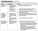
The doorbell does not work
1. Press the Mute button until all of the Mute lights are off.
2. 
polarity.
3. The doorbell might be out of range; try the doorbell in a different location.
4. Reconnect the doorbell. See .
Two ‘beep’ sounds are heard
after the normal tune

Range is reduced
1. 
mount the the doorbell or push button on or near metal structures.
2. Move the doorbell closer to the push button.
3. 
batteries may need to be replaced more often.


1-year limited warranty
Honeywell warrants this product, excluding battery, to be free from defects in workmanship or materials, under

any time during the warranty period the product is determined to be defective due to workmanship or materials,
Honeywell shall repair or replace it (at Honeywell’s option).
If the product is defective,
(i) return it, with a bill of sale or other dated proof of purchase, to the place from which you purchased it; or

product should be returned to the following address:

replacement product can be sent to you.
This warranty does not cover removal or reinstallation costs. This warranty shall not apply if it is shown by
Honeywell that the defect was caused by damage which occurred while the product was in the possession of a
consumer.
Honeywell’s sole responsibility shall be to repair or replace the product within the terms stated above.
HONEYWELL SHALL NOT BE LIABLE FOR ANY LOSS OR DAMAGE OF ANY KIND, INCLUDING ANY INCIDENTAL
OR CONSEQUENTIAL DAMAGES RESULTING, DIRECTLY OR INDIRECTLY, FROM ANY BREACH OF ANY
WARRANTY, EXPRESS OR IMPLIED, OR ANY OTHER FAILURE OF THIS PRODUCT. Some states do not allow the
exclusion or limitation of incidental or consequential damages, so this limitation may not apply to you.
THIS WARRANTY IS THE ONLY EXPRESS WARRANTY HONEYWELL MAKES ON THIS PRODUCT. THE DURATION
OF ANY IMPLIED WARRANTIES, INCLUDING THE WARRANTIES OF MERCHANTABILITY AND FITNESS FOR A
PARTICULAR PURPOSE, IS HEREBY LIMITED TO THE ONEYEAR DURATION OF THIS WARRANTY. Some states
do not allow limitations on how long an implied warranty lasts, so the above limitation may not apply to you.



8
FCC Regulations
This device complies with part 15 of the FCC Rules. Operation is subject to the following two conditions: (1) This
device may not cause harmful interference, and (2) this device must accept any interference received, including
interference that may cause undesired operation.


This equipment has been tested and found to comply with the limits for a Class B digital device, pursuant to part
15 of the FCC Rules. These limits are designed to provide reasonable protection against harmful interference
in a residential installation. This equipment generates, uses and can radiate radio frequency energy and, if not
installed and used in accordance with the instructions, may cause harmful interference to radio communications.
However, there is no guarantee that interference will not occur in a particular installation. If this equipment does
cause harmful interference to radio or television reception, which can be determined by turning the equipment off
and on, the user is encouraged to try to correct the interference by one or more of the following measures:
Reorient or relocate the receiving antenna.
Increase the separation between the equipment and receiver.
Connect the equipment into an outlet on a circuit different from that to which the receiver is connected.
Consult the dealer or an experienced radio/TV technician for help.
This transmitter must not be co-located or operating in conjunction with any other antenna or transmitter. This
equipment should be installed and operated with a minimum distance of 20 millimeters between the radiator and
your body.

IC Regulations
CAN ICES-3(B)/ NMB-3(B)

two conditions: (1) this device may not cause interference, and (2) this device must accept any interference,
including interference that may cause undesired operation of the device.

The device meets the exemption from the routine evaluation limits in section 2.5 of RSS 102 and compliance with

This transmitter must not be co-located or operating in conjunction with any other antenna or transmitter. This
equipment should be installed and operated with a minimum distance of 20 millimeters between the radiator and
your body.

33-00186EFS-01
Automation and Control Solutions
Solutions de régulation et d’automatisation
Soluciones de Control y Automatización
Honeywell International Inc.
1985 Douglas Drive North
Golden Valley, MN 55422
yourhome.honeywell.com
® U.S. Registered Trademark.
® Marque de commerce déposée aux É.-U.
® Marca registrada en EE. UU.
© 2016 Honeywell International Inc.
33-00186EFS—01 M.S. 05-16
Printed in U.S.A.
E302157
APPLIANCE CONTROL
Regulaciones FCC
Este dispositivo cumple con la Sección 15 de las regulaciones de la FCC. El funcionamiento está sujeto a las dos
condiciones siguientes: (1) este dispositivo no debe causar interferencia perjudicial y (2) este dispositivo deberá
aceptar cualquier interferencia que se reciba, incluyendo la interferencia que pudiese causar el funcionamiento no
deseado.


funcionar el equipo.
Este equipo fue probado y cumple con los límites de los dispositivos digitales clase B, conforme a la Sección 15
de las regulaciones de la FCC. Estos límites esn diseñados para ofrecer una protección razonable contra la
interferencia perjudicial en una instalación residencial. Este equipo genera, utiliza y puede irradiar energía de
radiofrecuencia y, si no se instala y se utiliza según las instrucciones, puede producir una interferencia perjudicial
en la comunicación radial. Sin embargo, no hay garantía de que no habrá interferencia en una instalación
particular. Si este equipo produce una interferencia perjudicial en la recepción televisiva o radial, lo cual puede
determinarse al apagar y encender el equipo, se recomienda que el usuario intente corregir la interferencia
tomando una o más de las siguientes medidas:
Vuelva a orientar o ubicar la antena receptora.
Aumente la distancia entre el equipo y el receptor.
Conecte el equipo a un tomacorriente en un circuito diferente a aquel en el que está conectado el receptor.
Consulte con su distribuidor o con un técnico experto en radio/televisión para recibir ayuda.
Este transmisor no debe estar ubicado ni funcionando conjuntamente con cualquier otra antena o transmisor.
Este equipo se debe instalar y hacer funcionar con una distancia mínima de 20 milímetros entre el radiador y su
cuerpo.

Regulaciones IC
CAN ICES-3(B)/ NMB-3(B)
Este dispositivo cumple con la(s) norma(s) RSS exentas de licencia de la industria de Canadá. El funcionamiento
está sujeto a las dos condiciones siguientes: (1) es posible que este dispositivo no cause interferencia y (2) este
dispositivo debe aceptar cualquier interferencia recibida, incluso la que puede producir un funcionamiento no
deseado del dispositivo.

El dispositivo cumple con la exención de los límites de la evaluación rutinaria de la sección 2.5 de RSS 102 y el

exposición y acatamiento de las normas de RF.
Este transmisor no debe estar ubicado ni funcionando conjuntamente con cualquier otra antena o transmisor.
Este equipo se debe instalar y hacer funcionar con una distancia mínima de 20 milímetros entre el radiador y su
cuerpo.

  • Page 1 1
  • Page 2 2
  • Page 3 3
  • Page 4 4
  • Page 5 5
  • Page 6 6
  • Page 7 7
  • Page 8 8
  • Page 9 9
  • Page 10 10
  • Page 11 11
  • Page 12 12
  • Page 13 13
  • Page 14 14
  • Page 15 15
  • Page 16 16
  • Page 17 17
  • Page 18 18
  • Page 19 19
  • Page 20 20
  • Page 21 21
  • Page 22 22
  • Page 23 23
  • Page 24 24

Honeywell International HS9-RDWL515P User manual

Type
User manual
This manual is also suitable for

Ask a question and I''ll find the answer in the document

Finding information in a document is now easier with AI