Microchip Technology EVB-SEC1212-DEV User manual
- Category
- Fax machines
- Type
- User manual
This manual is also suitable for

2013 Microchip Technology Inc. DS00001574A
EVB-SEC1110/EVB-SEC1210/
EVB-SEC1212-DEV
Evaluation Board User’s Guide

2013 Microchip Technology Inc. DS00001574A-page 2
Information contained in this publication regarding device
applications and the like is provided only for your convenience
and may be superseded by updates. It is your responsibility to
ensure that your application meets with your specifications.
MICROCHIP MAKES NO REPRESENTATIONS OR
WARRANTIES OF ANY KIND WHETHER EXPRESS OR
IMPLIED, WRITTEN OR ORAL, STATUTORY OR
OTHERWISE, RELATED TO THE INFORMATION,
INCLUDING BUT NOT LIMITED TO ITS CONDITION,
QUALITY, PERFORMANCE, MERCHANTABILITY OR
FITNESS FOR PURPOSE. Microchip disclaims all liability
arising from this information and its use. Use of Microchip
devices in life support and/or safety applications is entirely at
the buyer’s risk, and the buyer agrees to defend, indemnify and
hold harmless Microchip from any and all damages, claims,
suits, or expenses resulting from such use. No licenses are
conveyed, implicitly or otherwise, under any Microchip
intellectual property rights.
Note the following details of the code protection feature on Microchip devices:
• Microchip products meet the specification contained in their particular Microchip Data Sheet.
• Microchip believes that its family of products is one of the most secure families of its kind on the market today, when used in the
intended manner and under normal conditions.
• There are dishonest and possibly illegal methods used to breach the code protection feature. All of these methods, to our
knowledge, require using the Microchip products in a manner outside the operating specifications contained in Microchip’s Data
Sheets. Most likely, the person doing so is engaged in theft of intellectual property.
• Microchip is willing to work with the customer who is concerned about the integrity of their code.
• Neither Microchip nor any other semiconductor manufacturer can guarantee the security of their code. Code protection does not
mean that we are guaranteeing the product as “unbreakable.”
Code protection is constantly evolving. We at Microchip are committed to continuously improving the code protection features of our
products. Attempts to break Microchip’s code protection feature may be a violation of the Digital Millennium Copyright Act. If such acts
allow unauthorized access to your software or other copyrighted work, you may have a right to sue for relief under that Act.
Microchip received ISO/TS-16949:2009 certification for its worldwide
headquarters, design and wafer fabrication facilities in Chandler and
Tempe, Arizona; Gresham, Oregon and design centers in California
and India. The Company’s quality system processes and procedures
are for its PIC
®
MCUs and dsPIC
®
DSCs, KEELOQ
®
code hopping
devices, Serial EEPROMs, microperipherals, nonvolatile memory and
analog products. In addition, Microchip’s quality system for the design
and manufacture of development systems is ISO 9001:2000 certified.
QUALITY MANAGEMENT S
YSTEM
CERTIFIED BY DNV
== ISO/TS 16949 ==
Trademarks
The Microchip name and logo, the Microchip logo, dsPIC,
FlashFlex, K
EELOQ, KEELOQ logo, MPLAB, PIC, PICmicro,
PICSTART, PIC
32
logo, rfPIC, SST, SST Logo, SuperFlash
and UNI/O are registered trademarks of Microchip Technology
Incorporated in the U.S.A. and other countries.
FilterLab, Hampshire, HI-TECH C, Linear Active Thermistor,
MTP, SEEVAL and The Embedded Control Solutions
Company are registered trademarks of Microchip Technology
Incorporated in the U.S.A.
Silicon Storage Technology is a registered trademark of
Microchip Technology Inc. in other countries.
Analog-for-the-Digital Age, Application Maestro, BodyCom,
chipKIT, chipKIT logo, CodeGuard, dsPICDEM,
dsPICDEM.net, dsPICworks, dsSPEAK, ECAN,
ECONOMONITOR, FanSense, HI-TIDE, In-Circuit Serial
Programming, ICSP, Mindi, MiWi, MPASM, MPF, MPLAB
Certified logo, MPLIB, MPLINK, mTouch, Omniscient Code
Generation, PICC, PICC-18, PICDEM, PICDEM.net, PICkit,
PICtail, REAL ICE, rfLAB, Select Mode, SQI, Serial Quad I/O,
Total Endurance, TSHARC, UniWinDriver, WiperLock, ZENA
and Z-Scale are trademarks of Microchip Technology
Incorporated in the U.S.A. and other countries.
SQTP is a service mark of Microchip Technology Incorporated
in the U.S.A.
GestIC and ULPP are registered trademarks of Microchip
Technology Germany II GmbH & Co. & KG, a subsidiary of
Microchip Technology Inc., in other countries.
All other trademarks mentioned herein are property of their
respective companies.
© 2013, Microchip Technology Incorporated, Printed in the
U.S.A., All Rights Reserved.
ISBN: 9781620774649

2013 Microchip Technology Inc. DS00001574A-page 3
Object of Declaration:
EVB-SEC1110/EVB-SEC1210/EVB-SEC1212-DEV User’s Guide

EVB-SEC1110/EVB-SEC1210/EVB-SEC1212-DEV
Evaluation Board User’s Guide
DS00001574A-page 4 2013 Microchip Technology Inc.
NOTES:

EVB-SEC1110/EVB-SEC1210/EVB-SEC1212-DEV
EVALUATION BOARD
USER’S GUIDE
2013 Microchip Technology Inc. DS00001574A-page 5
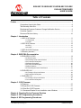
Table of Contents
Preface ........................................................................................................................... 7
Conventions Used in this Guide ............................................................................ 8
The Microchip Web Site ........................................................................................ 9
Development Systems Customer Change Notification Service ............................ 9
Customer Support ................................................................................................. 9
Document Revision History ................................................................................. 10
Chapter 1. Introduction
1.1 SEC1110 Features ....................................................................................... 11
1.1.1 Smartcard .................................................................................................. 11
1.1.2 USB ........................................................................................................... 11
1.2 SEC1210 Features ....................................................................................... 12
1.2.1 SPI1 ........................................................................................................... 12
1.2.2 UART ......................................................................................................... 12
1.3 SEC1212-DEV Features .............................................................................. 12
1.4 Directory structure ........................................................................................ 13
Chapter 2. EVBPCBA Documentation
2.5 EVB-SEC2112-DEV ..................................................................................... 14
2.5.1 Board Layout ............................................................................................. 16
2.5.2 Inserting a Chip into the Socket ................................................................ 17
2.5.3 Connector Description ............................................................................... 17
2.5.4 Switch Description ..................................................................................... 20
2.5.5 Test Points Description ............................................................................. 20
2.5.6 Bond Options ............................................................................................. 20
2.5.7 Selecting the Code Fetch Source .............................................................. 21
2.6 EVB-SEC1210 .............................................................................................. 21
2.6.1 Placing a Chip in the Socket ..................................................................... 22
2.6.2 Connector Description ............................................................................... 23
2.7 EVB-SEC1110 .............................................................................................. 24
2.7.1 Placing a Chip in the Socket ..................................................................... 25
2.7.2 Connector Description ............................................................................... 26
Chapter 3. CCID Firmware
3.8 Features ....................................................................................................... 27
3.9 Single Slot CCID Firmware .......................................................................... 27
3.10 Dual Slot CCID Firmware ........................................................................... 27
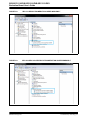
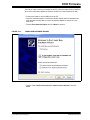
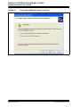
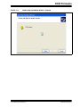
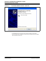
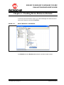
3.11 Smartcard Reader Driver Installation under Windows ............................... 27
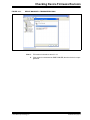
Chapter 4. Checking Device Firmware Revision
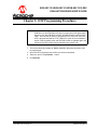
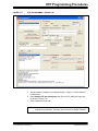
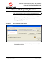
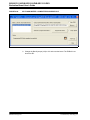
Chapter 5. OTP Programming Procedures
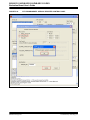
Chapter 6. SPI Programming Procedures


EVB-SEC1110/EVB-SEC1210/EVB-SEC1212-DEV
EVALUATION BOARD USER’S GUIDE
2013 Microchip Technology Inc. DS00001574A-page 7
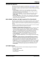
Preface
NOTICE TO CUSTOMERS
All documentation becomes dated, and this manual is no exception. Microchip tools and
documentation are constantly evolving to meet customer needs, so some actual dialogs
and/or tool descriptions may differ from those in this document. Please refer to our web site
(www.microchip.com) to obtain the latest documentation available.
Documents are identified with a “DS” number. This number is located on the bottom of each
page, in front of the page number. The numbering convention for the DS number is
“DSXXXXXA”, where “XXXXX” is the document number and “A” is the revision level of the
document.
For the most up-to-date information on development tools, see the MPLAB
®
IDE online help.
Select the Help menu, and then Topics to open a list of available online help files.

EVB-SEC1110/EVB-SEC1210/EVB-SEC1212-DEV
Evaluation Board User’s Guide
DS00001574A-page 8 2013 Microchip Technology Inc.
CONVENTIONS USED IN THIS GUIDE
This manual uses the following documentation conventions:
DOCUMENTATION CONVENTIONS
Description Represents Examples
Arial font:
Italic characters Referenced books MPLAB
®
IDE User’s Guide
Emphasized text ...is the only compiler...
Initial caps A window the Output window
A dialog the Settings dialog
A menu selection select Enable Programmer
Quotes A field name in a window or
dialog
“Save project before build”
Underlined, italic text with
right angle bracket
A menu path File>Save
Bold characters A dialog button Click OK
A tab Click the Power tab
N‘Rnnnn A number in verilog format,
where N is the total number of
digits, R is the radix and n is a
digit.
4‘b0010, 2‘hF1
Text in angle brackets < > A key on the keyboard Press <Enter>, <F1>
Courier New font:
Plain Courier New Sample source code #define START
Filenames autoexec.bat
File paths c:\mcc18\h
Keywords _asm, _endasm, static
Command-line options -Opa+, -Opa-
Bit values 0, 1
Constants 0xFF, ‘A’
Italic Courier New A variable argument file.o, where file can be
any valid filename
Square brackets [ ] Optional arguments mcc18 [options] file
[options]
Curly brackets and pipe
character: { | }
Choice of mutually exclusive
arguments; an OR selection
errorlevel {0|1}
Ellipses... Replaces repeated text var_name [,
var_name...]
Represents code supplied by
user
void main (void)
{ ...
}

Preface
2013 Microchip Technology Inc. DS00001574A-page 9
THE MICROCHIP WEB SITE
Microchip provides online support via our web site at www.microchip.com. This web
site is used as a means to make files and information easily available to customers.
Accessible by using your favorite Internet browser, the web site contains the following
information:
• Product Support – Data sheets and errata, application notes and sample
programs, design resources, user’s guides and hardware support documents,
latest software releases and archived software
• General Technical Support – Frequently Asked Questions (FAQs), technical
support requests, online discussion groups, Microchip consultant program
member listing
• Business of Microchip – Product selector and ordering guides, latest Microchip
press releases, listing of seminars and events, listings of Microchip sales offices,
distributors and factory representatives
DEVELOPMENT SYSTEMS CUSTOMER CHANGE NOTIFICATION SERVICE
Microchip’s customer notification service helps keep customers current on Microchip
products. Subscribers will receive e-mail notification whenever there are changes,
updates, revisions or errata related to a specified product family or development tool of
interest.
To register, access the Microchip web site at www.microchip.com, click on Customer
Change Notification and follow the registration instructions.
The Development Systems product group categories are:
• Compilers – The latest information on Microchip C compilers, assemblers, linkers
and other language tools. These include all MPLAB C compilers; all MPLAB
assemblers (including MPASM assembler); all MPLAB linkers (including MPLINK
object linker); and all MPLAB librarians (including MPLIB object librarian).
• Emulators – The latest information on Microchip in-circuit emulators.This
includes the MPLAB REAL ICE and MPLAB ICE 2000 in-circuit emulators.
• In-Circuit Debuggers – The latest information on the Microchip in-circuit
debuggers. This includes MPLAB ICD 3 in-circuit debuggers and PICkit 3 debug
express.
• MPLAB IDE – The latest information on Microchip MPLAB IDE, the Windows
Integrated Development Environment for development systems tools. This list is
focused on the MPLAB IDE, MPLAB IDE Project Manager, MPLAB Editor and
MPLAB SIM simulator, as well as general editing and debugging features.
• Programmers – The latest information on Microchip programmers. These include
production programmers such as MPLAB REAL ICE in-circuit emulator, MPLAB
ICD 3 in-circuit debugger and MPLAB PM3 device programmers. Also included
are nonproduction development programmers such as PICSTART Plus and
PIC-kit 2 and 3.
CUSTOMER SUPPORT
Users of Microchip products can receive assistance through several channels:
• Distributor or Representative
• Local Sales Office
• Field Application Engineer (FAE)
• Technical Support

EVB-SEC1110/EVB-SEC1210/EVB-SEC1212-DEV
Evaluation Board User’s Guide
DS00001574A-page 10 2013 Microchip Technology Inc.
Customers should contact their distributor, representative or field application engineer
(FAE) for support. Local sales offices are also available to help customers. A listing of
sales offices and locations is included in the back of this document.
Technical support is available through the web site at:
http://www.microchip.com/support
DOCUMENT REVISION HISTORY
Revision A (September 2013)
• Initial Release of this Document.

EVB-SEC1110/EVB-SEC1210/EVB-SEC1212-DEV
EVALUATION BOARD USER’S GUIDE
2013 Microchip Technology Inc. DS00001574A-page 11
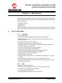
Chapter 1. Introduction
The SEC1110/SEC1210/SEC1212-DEV is a family low power, OEM configurable, sin-
gle-chip smartcard reader solutions. Three evaluation boards (EVBs) are available for
device development:
• EVB-SEC2112-DEV
• EVB-SEC1210
• EVB-SEC1110
These EVBs demonstrate standalone solutions with all of the interfaces and features
listed the following sub-sections. For details on each individual EVB, refer to Chapter 2.
1.1 SEC1110 FEATURES
1.1.1 Smartcard
• Single Smartcard slot
• Fully compliant with the ISO/IEC 7816, EMV and PC/SC standards
• Versatile ETU rate generation, supporting current and proposed rates (to 861
Kbps and beyond)
• Full support of both T=0 and T=1 protocols
• Full-packet FIFO (259 bytes) for transmit and receive
• Half-Duplex operation, with no software intervention required between transmit
and receive phases of an exchange
• Very loose real-time response required of software
• (worst case scenario of approximately 180 ms)
• Dynamically programmable FIFO threshold, with byte granularity
• Time-out FIFO flush interrupt, independent of threshold
• Programmable Smart Card clock frequency
• UART-like register file structure
• Supports Class A, Class B, Class C, or Class AB Smart Cards (all 1.8 V, 3 V and
5 V cards)
• Automatic Character Repetition for T=0 protocol Parity Error recovery
• Automatic card deactivation on card removal and on other system events, includ-
ing persistent Parity Errors
1.1.2 USB
• Supports Full-Speed data transfer
• Endpoints can be configured for control, bulk & interrupt transfer types
• Max packet size configurable for each endpoint
• (8 / 16/ 32/ 64 bytes are allowed)
• Ping pong buffers supported for non-control endpoints

EVB-SEC1110/EVB-SEC1210/EVB-SEC1212-DEV
Evaluation Board User’s Guide
DS00001574A-page 12 2013 Microchip Technology Inc.
• Supports Suspend, Resume, and Remote Wakeup per the USB specification
requirements
• Endpoint buffer may be located anywhere in the 1.5K SRAM, as per the alignment
requirements based on the max packet size
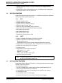
1.2 SEC1210 FEATURES
Along with the features mentioned in Section 1.1, the SEC1210 includes two Smartcard
slots and the following additional features:
1.2.1 SPI1
• Supports full-duplex mode
• Supports master or slave mode
• Supports seven SPI1 Master baud rates
• Slave Clock rate up to spi1_clk/8
• Serial clock with programmable polarity and phase
• Master Mode fault error flag with MCU interrupt capability
• Write collision flag protection
• Byte Transfer/Receive APIs
• Bulk Transfer/ Receive APIs
• Simultaneous Transfer/ Receive APIs
1.2.2 UART
• Software compatible with Standard 16C450 and 16C550A
• Separate 16 byte FIFO for transmission and reception
- Prevents buffer overrun
- Helps software to be less time critical in handling transmission / reception
• Programmable baud rate generator - Up to 3 Mbps baud rate can be achieved
• Supports flow control using RTS / CTS signals
• Pin Polarity control
• Programmable communication parameters:
- Word length - 5, 6, 7, 8 bits
- Stop bits - 1, 1.5, 2 bits
- Parity - None, Odd, Even, Mark, Space
• Low power sleep mode available
1.3 SEC1212-DEV FEATURES
Along with the features mentioned in section 1.1 and1.2 the following modules are also
available in the SEC1212-DEV:
• Boot from SPI2 Interface
• The SVB is equipped with a 1Kbyte Atmel SPI flash (AT26DF081A-SSU). SPI
flash from Atmel and Windbond are supported.
• On-board RS232 Transceiver for debugging as well as RS232 host interface
• On-board Reset button
• On-board EDP header for f/w debugging.
• On-board JTAG header for entering ASIC test mode and debugging
Note: A voltage level shifter board / cable is required to connect the UART port to
the PC. An FTDI cable is used for this.

Introduction
2013 Microchip Technology Inc. DS00001574A-page 13
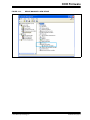
1.4 DIRECTORY STRUCTURE
The EVB-SEC2112-DEV release package provides the following file/folder structure:
EVB Schematics & BOM
Contains EVB schematics and BOM
SW Tools/WinUSB Driver
This is the device driver required for BootROM USB Device
SW Tools/OTPProgrammer
Contains the OTP programming utility and user manual
SW Tools/Linux Libraries
Contains the required Linux libraries
SW Tools/SPIFlashUtitly
Contains utility to program the SEC1212-DEV SPI2 flash and the relevant user manual.
Firmware
This folder contains the firmware binary files for programming into the OTP / SPI Flash.
Filenames with "SPI2" are intended to be programmed onto the SPI flash using SPI-
FlashWriter application. Filenames with "OTP" are intended to be programmed onto
the OTP using OTPProgrammer application. Similarly, "SINGLESLOT" or
"DUALSLOT" in the file name indicates a single slot or dual slot reader, respectively.

EVB-SEC1110/EVB-SEC1210/EVB-SEC1212-DEV
EVALUATION BOARD USER’S GUIDE
2013 Microchip Technology Inc. DS00001574A-page 14
Chapter 2. EVBPCBA Documentation
This chapter details the evaluation boards available for the SEC family of ASIC's and
their hardware settings. A standard USB A-to-B cable is required to connect the EVB
to the USB Host.
2.5 EVB-SEC2112-DEV
The EVB-SEC2112-DEV includes a 48-pin QFN SEC1212-DEV with the following
interfaces and features:
• USB host interface
• Two smartcard slots
• SPI1
• SPI2 Code execution (Either from external or on board flash)
•UART
• Input bond options allow a single chip to function as either an SEC1110 or
SEC1210.

EVBPCBA Documentation
2013 Microchip Technology Inc. DS00001574A-page 15
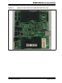
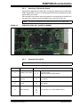
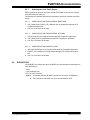
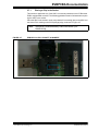
FIGURE 2-1: EVB-SEC2112-DEV PROTOTYPE COMPONENT SIDE TOP LAYER

EVB-SEC1110/EVB-SEC1210/EVB-SEC1212-DEV
Evaluation Board User’s Guide
DS00001574A-page 16 2013 Microchip Technology Inc.
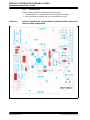
2.5.1 Board Layout
Please follow this legend to understand the following figure.
1. In each header, Pin 1 is represented by a thick band near the edge.
2. Pins filled in dark red indicate they are to be shorted by a jumper.
FIGURE 2-2: DEFAULT BOARD SETUP TO RUN FROM OTP USING INTERNAL OSCILLATOR
IN SEC1212-DEV (QFN48) MODE

EVBPCBA Documentation
2013 Microchip Technology Inc. DS00001574A-page 17
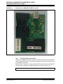
2.5.2 Inserting a Chip into the Socket
This section is applicable only if the ASIC is not directly soldered on the PCB and the
EVB is equipped with a socket. The following guidelines must be followed when replac-
ing the ASIC in the socket.
Place the ASIC in the socket in such a way that the Pin1 marking (dot) on the ASIC and
the socket Pin1 marking on the PCB (triangle) align, as shown in Figure 2-3.
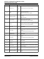
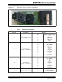
2.5.3 Connector Description
Note: The socket is manufactured by R&D Interconnect (P/N: 106458-0020).
FIGURE 2-3: EVB-SEC2112-DEV PIN 1 SOCKET ALIGNMENT
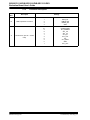
Note: The board’s default settings are indicated in the Settings column.
Connector Description Settings
J2 Self/Bus Power Header
1 --- 2
2 --- 3
Supplied Externally
Supplied by Upstream VBUS (default)
J3 Power IN 1-2 Short (default)
J4 5V_DUT 1-2 Short (default)
J9 MUX’d RS232-I/F
1-2
3-4
5-6
7-8
Short (and open J11) to select RS232 interface

EVB-SEC1110/EVB-SEC1210/EVB-SEC1212-DEV
Evaluation Board User’s Guide
DS00001574A-page 18 2013 Microchip Technology Inc.
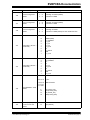
J11 MUX’d SPI1-I/F
1-2
3-4
5-6
7-8
Short (and open J9) to select SPI1 interface
J12 TEST
1-2
2-3
Chip will enter TEST mode
Chip will enter functional mode (default)
J13 JTAG Select Header
1 --- 2
2 --- 3
JTAG_CLK (JTAG CLK is routed from J39 when this setting
is selected)
VBUS_DET(default)
J14 PCLK_ENABLE
1-2
2-3
Chip starts with external oscillator
Chip starts with internal oscillator (default)
J15 OSC_IN 1-2
External oscillator is fed to PCLK_IN_48MHZ. To be shorted
if the chip is to work from external oscillator
J20 SC1_Load 1-2 Open (default)
J21 SC1_PRSNT
1-2
2-3
SC1 Card detect pin routed from smartcard connector
(default)
SC1 card detect pin is permanently grounded
J26 BootROM select 1-2 Open (default)
J27 SC2_PRSNT
1-2
2-3
SC2 Card detect pin routed from smartcard connector
(default)
SC2 card detect pin is permanently grounded
J28 SC2_Load 1-2 Open (default)
J29 OSC_SEL Unused Open (default)
J31 SPI1_Interface 1-10
Open (default). Header for connecting Cheetah / Aardvark
SPI host adapters
J34 SPI2_Internal Flash 1-8 Short to program SPI2 flash and execute code from
J35 RS232 10 pin header 1-10
Header to which Microchip’s 10 pin serial cable to be con-
nected
Connector Description Settings

EVBPCBA Documentation
2013 Microchip Technology Inc. DS00001574A-page 19
J36
Bond 0 Configuration
Header
1 --- 2
2 --- 3
Pulled high to VDD33 (default)
Pulled down to GND
J37
Bond 1 Configuration
Header
1 --- 2
2 --- 3
Pulled high to VDD33 (default)
Pulled down to GND
J38
Bond 2 Configuration
Header
1 --- 2
2 --- 3
Pulled high to VDD33
Pulled down to GND (default) for OTP / ROM execution
J19
Smart Card 1 (SC1 I/F –
Credit Card)
10
9
8
4
7
3
6
2
5
1
CDSW2 (GND)
SC1_PRSNT#
SC1_C8
SC1_C4
SC1_IO
SC1_CLK
NC
SC1_RST#
GND
SC1_VCC
J25
Smart Card 2 (SC2 I/F –
Credit Card)
10
9
8
4
7
3
6
2
5
1
CDSW2 (GND)
SC2_PRSNT#
NC
NC
SC2_IO
SC2_CLK
NC
SC2_RST#
GND
SC2_VCC
J39
DUT EDP/EDP-T JTAG
Header
2,6,10,16
1,3,4,5,7,9
,11,13,15,
17,19,20
8
12
14
18
nc pins
GND Test Points
TCK (JTAG_CLK)
TDO (PJTAG_TDO)
TDI (PJTAG_TDI)
TMS (PJTAG_TMS)
J40
General purpose pull up
to 3.3V thru 1K ohm
resistor
1-4 Open (default)
Connector Description Settings

EVB-SEC1110/EVB-SEC1210/EVB-SEC1212-DEV
Evaluation Board User’s Guide
DS00001574A-page 20 2013 Microchip Technology Inc.
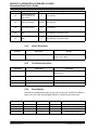
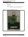
2.5.4 Switch Description
2.5.5 Test Points Description
2.5.6 Bond Options
Depending on the Bond option set on jumper J36, J37 and J38, the SEC1212-DEV pro-
totype can work in SEC1210 (QFN24) and SEC1110 (QFN16) pin modes also.
J41
General purpose pull
down to GND thru 1K
ohm resistor
1-4 Open (default)
J42 Open JTAG Header Unused Open (default)
J43 LED Polarity control 2-3 Short (default)
J44 3V3 1-4 Open (default). Connected to 3.3V
J45 GND 1-4 Open (default). Connected to GND
Connector Description Settings
Ref. Des Description Settings
SW2 Reset Switch Press : In Reset
Release : Out of Reset
Test Point Description Connection
TP1 5V 5V input to MIC37100 3.3V regulator (U1) &
SEC1210 (U2)
TP2 3.3V 3.3V output of MIC37100 3.3V regulator (U1)
TP4 GND GND
TP5 VDD33 VDD33 power output of internal regulator
PART No. BOND0(J36) BOND1(J37) BONd2(J38) Remarks
SEC1110 0 0 x
SEC1210 0 1 x
SEC1212-DEV 1 1 0 OTP/Internal ROM boot
SEC1212-DEV 1 1 1 External SPI2 Flash boot
Page is loading ...
Page is loading ...
Page is loading ...
Page is loading ...
Page is loading ...
Page is loading ...
Page is loading ...
Page is loading ...
Page is loading ...
Page is loading ...
Page is loading ...
Page is loading ...
Page is loading ...
Page is loading ...
Page is loading ...
Page is loading ...
Page is loading ...
Page is loading ...
Page is loading ...
Page is loading ...
Page is loading ...
Page is loading ...
-
 1
1
-
 2
2
-
 3
3
-
 4
4
-
 5
5
-
 6
6
-
 7
7
-
 8
8
-
 9
9
-
 10
10
-
 11
11
-
 12
12
-
 13
13
-
 14
14
-
 15
15
-
 16
16
-
 17
17
-
 18
18
-
 19
19
-
 20
20
-
 21
21
-
 22
22
-
 23
23
-
 24
24
-
 25
25
-
 26
26
-
 27
27
-
 28
28
-
 29
29
-
 30
30
-
 31
31
-
 32
32
-
 33
33
-
 34
34
-
 35
35
-
 36
36
-
 37
37
-
 38
38
-
 39
39
-
 40
40
-
 41
41
-
 42
42


Microchip Technology EVB-SEC1212-DEV User manual
- Category
- Fax machines
- Type
- User manual
- This manual is also suitable for
Ask a question and I''ll find the answer in the document
Finding information in a document is now easier with AI
Related papers
-
Microchip Technology MPLAB User manual
-
-
-
-
-
-
-
-
-
Other documents
-
MICROCHIP EVB-LAN7800LC-1 Operating instructions
-
-
-
-
-
-
-
-
-