Microchip Technology EVB-LAN9252-SPI Quick start guide
- Type
- Quick start guide

2017 Microchip Technology Inc. DS50002604A
EVB-LAN9252-SPI
Quick Start Guide

DS50002604A-page 2 2017 Microchip Technology Inc.
Information contained in this publication regarding device applications and the like is provided only for your convenience and may be
superseded by updates. It is your responsibility to ensure that your application meets with your specifications. MICROCHIP MAKES NO
REPRESENTATIONS OR WARRANTIES OF ANY KIND WHETHER EXPRESS OR IMPLIED, WRITTEN OR ORAL, STATUTORY OR
OTHERWISE, RELATED TO THE INFORMATION, INCLUDING BUT NOT LIMITED TO ITS CONDITION, QUALITY, PERFORMANCE,
MERCHANTABILITY OR FITNESS FOR PURPOSE. Microchip disclaims all liability arising from this information and its use. Use of Micro-
chip devices in life support and/or safety applications is entirely at the buyer’s risk, and the buyer agrees to defend, indemnify and hold
harmless Microchip from any and all damages, claims, suits, or expenses resulting from such use. No licenses are conveyed, implicitly or
otherwise, under any Microchip intellectual property rights unless otherwise stated.
Trademarks
The Microchip name and logo, the Microchip logo, AnyRate, AVR, AVR logo, AVR Freaks, BeaconThings, BitCloud, CryptoMemory, CryptoRF,
dsPIC, FlashFlex, flexPWR, Heldo, JukeBlox, KEELOQ, KEELOQ logo, Kleer, LANCheck, LINK MD, maXStylus, maXTouch, MediaLB, megaAVR,
MOST, MOST logo, MPLAB, OptoLyzer, PIC, picoPower, PICSTART, PIC32 logo, Prochip Designer, QTouch, RightTouch, SAM-BA, SpyNIC,
SST, SST Logo, SuperFlash, tinyAVR, UNI/O, and XMEGA are registered trademarks of Microchip Technology Incorporated in the U.S.A. and
other countries.
ClockWorks, The Embedded Control Solutions Company, EtherSynch, Hyper Speed Control, HyperLight Load, IntelliMOS, mTouch, Precision
Edge, and Quiet-Wire are registered trademarks of Microchip Technology Incorporated in the U.S.A.
Adjacent Key Suppression, AKS, Analog-for-the-Digital Age, Any Capacitor, AnyIn, AnyOut, BodyCom, chipKIT, chipKIT logo, CodeGuard,
CryptoAuthentication, CryptoCompanion, CryptoController, dsPICDEM, dsPICDEM.net, Dynamic Average Matching, DAM, ECAN,
EtherGREEN, In-Circuit Serial Programming, ICSP, Inter-Chip Connectivity, JitterBlocker, KleerNet, KleerNet logo, Mindi, MiWi, motorBench,
MPASM, MPF, MPLAB Certified logo, MPLIB, MPLINK, MultiTRAK, NetDetach, Omniscient Code Generation, PICDEM, PICDEM.net, PICkit,
PICtail, PureSilicon, QMatrix, RightTouch logo, REAL ICE, Ripple Blocker, SAM-ICE, Serial Quad I/O, SMART-I.S., SQI, SuperSwitcher,
SuperSwitcher II, Total Endurance, TSHARC, USBCheck, VariSense, ViewSpan, WiperLock, Wireless DNA, and ZENA are trademarks of
Microchip Technology Incorporated in the U.S.A. and other countries.
SQTP is a service mark of Microchip Technology Incorporated in the U.S.A.
Silicon Storage Technology is a registered trademark of Microchip Technology Inc. in other countries.
GestIC is a registered trademark of Microchip Technology Germany II GmbH & Co. KG, a subsidiary of Microchip Technology Inc., in other
countries.
All other trademarks mentioned herein are property of their respective companies.
© 2017, Microchip Technology Incorporated, All Rights Reserved.
ISBN: 9781522417620
Note the following details of the code protection feature on Microchip devices:
• Microchip products meet the specification contained in their particular Microchip Data Sheet.
• Microchip believes that its family of products is one of the most secure families of its kind on the market today, when used in the
intended manner and under normal conditions.
• There are dishonest and possibly illegal methods used to breach the code protection feature. All of these methods, to our
knowledge, require using the Microchip products in a manner outside the operating specifications contained in Microchip’s Data
Sheets. Most likely, the person doing so is engaged in theft of intellectual property.
• Microchip is willing to work with the customer who is concerned about the integrity of their code.
• Neither Microchip nor any other semiconductor manufacturer can guarantee the security of their code. Code protection does not
mean that we are guaranteeing the product as “unbreakable.”
Code protection is constantly evolving. We at Microchip are committed to continuously improving the code protection features of our
products. Attempts to break Microchip’s code protection feature may be a violation of the Digital Millennium Copyright Act. If such acts
allow unauthorized access to your software or other copyrighted work, you may have a right to sue for relief under that Act.
Microchip received ISO/TS-16949:2009 certification for its worldwide
headquarters, design and wafer fabrication facilities in Chandler and
Tempe, Arizona; Gresham, Oregon and design centers in California
and India. The Company’s quality system processes and procedures
are for its PIC
®
MCUs and dsPIC
®
DSCs, KEELOQ
®
code hopping
devices, Serial EEPROMs, microperipherals, nonvolatile memory and
analog products. In addition, Microchip’s quality system for the design
and manufacture of development systems is ISO 9001:2000 certified.
QUALITYMANAGEMENTS
YSTEM
CER TIFIEDBYDNV
== ISO/TS16949==

2017 Microchip Technology Inc. DS50002604A-page 3
EU Declaration of Conformity
This declaration of conformity is issued by the manufacturer.
The development/evaluation tool is designed to be used for research and development in a laboratory environment. This
development/evaluation tool is not a Finished Appliance, nor is it intended for incorporation into Finished Appliances that are made
commercially available as single functional units to end users under EU EMC Directive 2004/108/EC and as supported by the European
Commission's Guide for the EMC Directive 2004/108/EC (8th February 2010).
This development/evaluation tool complies with EU RoHS2 Directive 2011/65/EU.
This development/evaluation tool, when incorporating wireless and radio-telecom functionality, is in compliance with the essential
requirement and other relevant provisions of the R&TTE Directive 1999/5/EC and the FCC rules as stated in the declaration of conformity
provided in the module datasheet and the module product page available at www.microchip.com.
For information regarding the exclusive, limited warranties applicable to Microchip products, please see Microchip’s standard terms and
conditions of sale, which are printed on our sales documentation and available at www.microchip.com.
Signed for and on behalf of Microchip Technology Inc. at Chandler, Arizona, USA.
Object of Declaration: EVB-LAN9252-SPI

EVB-LAN9252-SPI Quick Start Guide
DS50002604A-page 4 2017 Microchip Technology Inc.
NOTES:

EVB-LAN9252-SPI
QUICK START
GUIDE
2017 Microchip Technology Inc. DS50002604A-page 5
Table of Contents
Preface ...........................................................................................................................7
Introduction............................................................................................................7
Document Layout..................................................................................................7
Conventions Used in this Guide............................................................................8
The Microchip Web Site........................................................................................9
Development Systems Customer Change Notification Service ............................9
Customer Support.................................................................................................9
Document Revision History................................................................................. 10
Chapter 1. Overview
1.1 Introduction ...................................................................................................11
1.1.1 References ................................................................................................11
Chapter 2. EVB-LAN9252-SPI
2.1 EVB-LAN9252-SPI Board Design ................................................................13
2.1.1 SPI Headers ..............................................................................................13
2.1.2 Power ........................................................................................................14
2.1.3 Digital Interface Connector ........................................................................14
2.2 Interfacing with a Third Party Processor via SPI ..........................................14
2.2.1 Connect pins .............................................................................................14
2.2.2 Configure Slave Software ..........................................................................15
2.2.3 Configure System from EtherCAT Master .................................................15
Appendix A. EVB-LAN9252-SPI Evaluation Board Schematics
A.1 Introduction ..................................................................................................17
Worldwide Sales and Service ....................................................................................22

EVB-LAN9252-SPI Quick Start Guide
DS50002604A-page 6 2017 Microchip Technology Inc.
NOTES:

EVB-LAN9252-SPI
QUICK START
GUIDE
2017 Microchip Technology Inc. DS50002604A-page 7
Preface
INTRODUCTION
This chapter contains general information that will be useful to know before using and
configuring the EVB-LAN9252-SPI. Items discussed in this chapter include:
• Document Layout
• Conventions Used in this Guide
• The Microchip Web Site
• Development Systems Customer Change Notification Service
• Customer Support
• Document Revision History
DOCUMENT LAYOUT
This document describes how to configure the EVB-LAN9252-SPI, such as the DIGIO
and SPI, as well as various setup options, scanning, and programming. The manual
layout is as follows:
• Chapter 1. “Overview” – Shows a brief description of the EVB-LAN9252-SPI
board quick setup.
• Chapter 2. “EVB-LAN9252-SPI” – Provides instructions in configuring SPI.
• Appendix A. “EVB-LAN9252-SPI Evaluation Board Schematics” – This
appendix shows how to set up Master in Windows.
NOTICE TO CUSTOMERS
All documentation becomes dated, and this manual is no exception. Microchip tools and
documentation are constantly evolving to meet customer needs, so some actual dialogs
and/or tool descriptions may differ from those in this document. Please refer to our web site
(www.microchip.com) to obtain the latest documentation available.
Documents are identified with a “DS” number. This number is located on the bottom of each
page, in front of the page number. The numbering convention for the DS number is
“DSXXXXXA”, where “XXXXX” is the document number and “A” is the revision level of the
document.
For the most up-to-date information on development tools, see the MPLAB
®
IDE online help.
Select the Help menu, and then Topics to open a list of available online help files.

EVB-LAN9252-SPI Quick Start Guide
DS50002604A-page 8 2017 Microchip Technology Inc.
CONVENTIONS USED IN THIS GUIDE
This manual uses the following documentation conventions:
DOCUMENTATION CONVENTIONS
Description Represents Examples
Arial font:
Italic characters Referenced books MPLAB
®
IDE User’s Guide
Emphasized text ...is the only compiler...
Initial caps A window the Output window
A dialog the Settings dialog
A menu selection select Enable Programmer
Quotes A field name in a window or
dialog
“Save project before build”
Underlined, italic text with
right angle bracket
A menu path File>Save
Bold characters A dialog button Click OK
A tab Click the Power tab
N‘Rnnnn A number in verilog format,
where N is the total number of
digits, R is the radix and n is a
digit.
4‘b0010, 2‘hF1
Text in angle brackets < > A key on the keyboard Press <Enter>, <F1>
Courier New font:
Plain Courier New Sample source code #define START
Filenames autoexec.bat
File paths c:\mcc18\h
Keywords _asm, _endasm, static
Command-line options -Opa+, -Opa-
Bit values 0, 1
Constants 0xFF, ‘A’
Italic Courier New A variable argument file.o, where file can be
any valid filename
Square brackets [ ] Optional arguments mcc18 [options] file
[options]
Curly brackets and pipe
character: { | }
Choice of mutually exclusive
arguments; an OR selection
errorlevel {0|1}
Ellipses... Replaces repeated text var_name [,
var_name...]
Represents code supplied by
user
void main (void)
{ ...
}

Preface
2017 Microchip Technology Inc. DS50002604A-page 9
THE MICROCHIP WEB SITE
Microchip provides online support via our web site at www.microchip.com. This web
site is used as a means to make files and information easily available to customers.
Accessible by using your favorite Internet browser, the web site contains the following
information:
• Product Support – Data sheets and errata, application notes and sample
programs, design resources, user’s guides and hardware support documents,
latest software releases and archived software
• General Technical Support – Frequently Asked Questions (FAQs), technical
support requests, online discussion groups, Microchip consultant program
member listing
• Business of Microchip – Product selector and ordering guides, latest Microchip
press releases, listing of seminars and events, listings of Microchip sales offices,
distributors and factory representatives
DEVELOPMENT SYSTEMS CUSTOMER CHANGE NOTIFICATION SERVICE
Microchip’s customer notification service helps keep customers current on Microchip
products. Subscribers will receive e-mail notification whenever there are changes,
updates, revisions or errata related to a specified product family or development tool of
interest.
To register, access the Microchip web site at www.microchip.com, click on Customer
Change Notification and follow the registration instructions.
The Development Systems product group categories are:
• Compilers – The latest information on Microchip C compilers, assemblers, linkers
and other language tools. These include all MPLAB C compilers; all MPLAB
assemblers (including MPASM assembler); all MPLAB linkers (including MPLINK
object linker); and all MPLAB librarians (including MPLIB object librarian).
• Emulators – The latest information on Microchip in-circuit emulators.This
includes the MPLAB REAL ICE and MPLAB ICE 2000 in-circuit emulators.
• In-Circuit Debuggers – The latest information on the Microchip in-circuit
debuggers. This includes MPLAB ICD 3 in-circuit debuggers and PICkit 3 debug
express.
• MPLAB IDE – The latest information on Microchip MPLAB IDE, the Windows
Integrated Development Environment for development systems tools. This list is
focused on the MPLAB IDE, MPLAB IDE Project Manager, MPLAB Editor and
MPLAB SIM simulator, as well as general editing and debugging features.
• Programmers – The latest information on Microchip programmers. These include
production programmers such as MPLAB REAL ICE in-circuit emulator, MPLAB
ICD 3 in-circuit debugger and MPLAB PM3 device programmers. Also included
are nonproduction development programmers such as PICSTART Plus and
PIC-kit 2 and 3.
CUSTOMER SUPPORT
Users of Microchip products can receive assistance through several channels:
• Distributor or Representative
• Local Sales Office
• Field Application Engineer (FAE)
• Technical Support

EVB-LAN9252-SPI Quick Start Guide
DS50002604A-page 10 2017 Microchip Technology Inc.
Customers should contact their distributor, representative or field application engineer
(FAE) for support. Local sales offices are also available to help customers. A listing of
sales offices and locations is included in the back of this document.
Technical support is available through the web site at:
http://www.microchip.com/support
DOCUMENT REVISION HISTORY
Revisions Section/Figure/Entry Correction
DS50002604A (05-30-17) Initial release of document

EVB-LAN9252-SPI
QUICK START
GUIDE
2017 Microchip Technology Inc. DS50002604A-page 11
Chapter 1. Overview
1.1 INTRODUCTION
The EVB-LAN9252-SPI board is intended to be a generic interface to many third party
processors used in EtherCAT Slave applications. The EVB-LAN9252-SPI is designed
to be a simple interface to the SPI port, with test points for power and ground. The eval-
uation board uses standard RJ45 connectors to connect to the EtherCAT system and
can be used to begin software development of the EtherCAT Slave code before the
final hardware is completed.
1.1.1 References
The following documents should be referenced when using this quick start guide. See
your Microchip representative for availability.
• LAN9252 - 2/3-Port EtherCAT Slave Controller with Integrated Ethernet PHYs
• LAN9252 Migration Guide from the Beckhoff ET1100
• LAN9252_C2000_SDK_V1.0
• LAN9252_C2000_SDK_V1.1

EVB-LAN9252-SPI Quick Start Guide
DS50002604A-page 12 2017 Microchip Technology Inc.
NOTES:

EVB-LAN9252-SPI
QUICK START
GUIDE
2017 Microchip Technology Inc. DS50002604A-page 13
Chapter 2. EVB-LAN9252-SPI
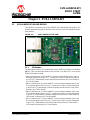
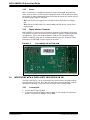
2.1 EVB-LAN9252-SPI BOARD DESIGN
This section is an overview of the EVB-LAN9252-SPI board design and interface. The
board is intended to provide an interface to the SPI port of a microcontroller develop-
ment platform.
FIGURE 2-1: EVB-LAN9252-SPI TOP VIEW
2.1.1 SPI Headers
The four signals used for SPI communication with LAN9252 are exposed via headers
(J4-J7). These can direct the signals to the connector J3 as HBI or SPI, or be used to
fly-wire SPI between boards.
• J4 is connected to pin 19 of LAN9252. Connect a jumper between pins 1 and 2 to
route the signal to the D9 pin of J3. Jumper pins 2 and 3 to connect the signal to
pin SCK of J3. Alternatively, remove the jumper and wire the SPI Clock directly to
pin 2 of this header.
• J5 is connected to pin 50 of the LAN9252. Connect a jumper between pins 1 and
2 to route the signal to the D5 pin of J3. Jumper pins 2 and 3 to connect the signal
to pin SCS# of J3. Alternatively, remove the jumper and wire the SPI Chip Select
directly to pin 2 of this header.
• J6 is connected to pin 13 of the LAN9252. Connect a jumper between pins 1 and
2 to route the signal to the D1 pin of J3. Jumper pins 2 and 3 to connect the signal
to pin S0 of J3. Alternatively, remove the jumper and wire the SPI Slave Data Out
(SPI Master In) directly to pin 2 of this header.
• J7 is connected to pin 17 of the LAN9252. Connect a jumper between pins 1 and
2 to route the signal to the D0 pin of J3. Jumper pins 2 and 3 to connect the signal
to pin SI of J3. Alternatively, remove the jumper and wire the SPI Slave Data In
(SPI Master Out) directly to pin 2 of this header.

EVB-LAN9252-SPI Quick Start Guide
DS50002604A-page 14 2017 Microchip Technology Inc.
2.1.2 Power
When connected to a compatible development system through J3, the power test
points are to be used to confirm a proper voltage is present on the board. When wiring
the board to an external development board, the power test points are used to connect
an external power supply to the board.
• TP2 is tied to the 3.3V supply for the LAN9252 and the EEPROM for configura-
tion.
• TP3 is tied to the GND plane of the board. Additional GND access can be found
on J8 and J9.
2.1.3 Digital Interface Connector
EVB-LAN9252-SPI also has a mass interface connector on the bottom of the board.
This interface is used to connect many of the LAN9252 signals to third party develop-
ment platforms. These pins enable evaluation of HBI and SPI abstraction using
LAN9252. LAN9252 must also be configured with the correct ESI (EtherCAT Slave
Information) via EEPROM for these signals to be active.
FIGURE 2-2: EVB-LAN9252-SPI BOTTOM VIEW
2.2 INTERFACING WITH A THIRD PARTY PROCESSOR VIA SPI
The EVB-LAN9252-SPI can be connected to any microprocessor development plat-
form with exposed SPI pins. Once the pins have been connected properly, software
development can begin. The process can be broken down into three steps:
2.2.1 Connect pins
1. Connect the SPI pins to J4-J7.
2. Connect to Power Test Points to a bench supply, or 3.3V supply on the processor
board. Connect GND to TP3 and 3.3V to TP2.

EVB-LAN9252-SPI
2017 Microchip Technology Inc. DS50002604A-page 15
2.2.2 Configure Slave Software
There are four ways to program the processor to act as an EtherCAT Slave Device. The
different methods have different degrees of development needed to get to a solution
ready for the next stage in the process.
• When using an existing EtherCAT Slave solution, refer to the LAN9252 Migration
guide for details on how to replace the existing ET1100 interface libraries with the
LAN9252 equivalent. All other code can remain the same.
• When using a processor with a LAN9252 SDK, the Slave Source Code (SSC) tool
from Beckhoff can be used to automatically generate EtherCAT Slave code. In the
SDK are template files that are used to speed the process along. Refer to the
LAN9252 product page for the latest SDKs in the software library section.
•The EVB-LAN9252_HBIPLUS_SDK_V1.3 is an example of an SDK that has tem-
plate libraries to help with development.
• When using a processor that only has LAN9252 drivers, the Slave Source Code
tool can still be used. There will not be template files for faster development, and
the developer will need to manually add the LAN9252 driver files into the SSC and
develop the processor specific interface code to the necessary peripherals used.
-The LAN9252_C2000_Drivers_V1.0 is an example of the drivers provided
for the LAN9252.
• When using a processor without any drivers, the developer will need to develop
both the LAN9252 SPI interface libraries as well as the processor specific inter-
face code to the peripherals used.
2.2.3 Configure System from EtherCAT Master
Once the Slave Source Code has been developed and programmed onto the proces-
sor, the LAN9252 can be connected to an EtherCAT Master. Use the ESI files and
EEPROM configuration settings to properly set up the LAN9252 for the desired digital
communication. Debug and test the Slave code in the full EtherCAT development envi-
ronment.

EVB-LAN9252-SPI Quick Start Guide
DS50002604A-page 16 2017 Microchip Technology Inc.
NOTES:

2017 Microchip Technology Inc. DS50002604A-page 17
EVB-LAN9252-SPI
QUICK START
GUIDE
Appendix A. EVB-LAN9252-SPI Evaluation Board
Schematics
A.1 INTRODUCTION
This appendix shows the EVB-LAN9252-SPI Evaluation Board Schematics.

EVB-LAN9252-SPI Quick Start Guide
DS50002604A-page 18 2017 Microchip Technology Inc.
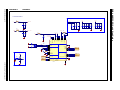
FIGURE A-1: LAN9252-1
POWER
INT PORT0INT PORT1
OSC
I2C
FXSDA/FXLOSA/FXSDENA
9
FXSDB/FXLOSB/FXSDENB
10
VDD33TXRX1
51
TXNA
52
TXPA
53
RXNA
54
RXPA
55
VDD12TX1
56
RBIAS
57
VDD33BIAS
58
VDD12TX2
59
RXPB
60
RXNB
61
TXPB
62
TXNB
63
VDD33TXRX2
64
OSCI
1
OSCO
2
OSCVDD12
3
OSCVSS
4
REG_EN
7
FXLOSEN
8
RST#
11
IRQ
44
TESTMODE
41
EESCL/TCK
43
EESDA/TMS
42
LINKACTLED0/TDO/CHIP_MODE0
48
LINKACTLED1/TDI/CHIP_MODE1
46
RUNLED/E2PSIZE
45
VDD33
5
VDDIO1
14
VDDIO2
20
VDDIO3
32
VDDIO4
37
VDDIO5
47
VDDCR1
6
VDDCR2
24
VDDCR3
38
GND
65
U1A
0.1uF
25V
0603
C19
3V3 3V3
VDDCR
TXA_N
TXA_P
RXA_N
RXA_P
TXB_N
TXB_P
RXB_N
RXB_P
3V3
12.1k
0603
1%
R1
RST#
I2C_SCL
I2C_SDL
GPIO0
GPIO1
GPIO2
25MHz
Y1
18pF
50V
0603
C20
18pF
50V
0603
C21
Note: OSCVSS need to connect to Chip GND
0.1uF
25V
0603
C4
VDD12TX2
VDD12TX1
3V3
Low ESR
470pF
25V
0603
C14
VDDCR
VDD33TXRX1
VDD33TXRX2
3V3
BLM18EG221SN1D
FB1
0.1uF
25V
0603
C2
BLM18EG221SN1D
FB2
0.1uF
25V
0603
C18
3V3
3V3
VDD33TXRX1
VDD33TXRX2
BLM18EG221SN1D
FB3
BLM18EG221SN1D
FB4
LAN9252-PART1
10k
0603
1%
R2
0.1uF
25V
0603
C22
3V3
RST#
RESET CKT
Power Supply Filtering
DNP
TP1
IRQ
VDD12TX2
VDD12TX1
0.1uF
25V
0603
C5
OSCI
OSCO
0.1uF
25V
0603
C7
0.1uF
25V
0603
C8
0.1uF
25V
0603
C9
0.1uF
25V
0603
C10
0.1uF
25V
0603
C11
0.1uF
25V
0603
C12
1uF
16V
0603
C13
0R
0603
R25
C13 & C14 Close to Pin6
1uF
16V
0603
DNP
C3
1uF
16V
0603
DNP
C6
1uF
16V
0603
DNP
C1
1uF
16V
0603
DNP
C17
0.1uF
25V
0603
C15
0.1uF
25V
0603
C16
1
42
3
SW1
DNP
TP4

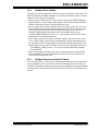
2017 Microchip Technology Inc. DS50002604A-page 19
FIGURE A-2: LAN CONNECTORS, STRAP & EEPROM
VDD33TXRX1
3V3
1k
0603
5%
R3
I2C_SCL
I2C_SDL
GPIO2
GPIO0
0R
0603
R8
0.022uF
50V
0603
C27
TXA_N
TXA_P
RXA_N
RXA_P
10pF
50V
0603
DNP
C23
10pF
50V
0603
DNP
C24
10pF
50V
0603
DNP
C25
10pF
50V
0603
DNP
C26
49.9R
0603
1%
R4
49.9R
0603
1%
R5
49.9R
0603
1%
R6
49.9R
0603
1%
R7
Br Grn
D1
270R
0603
5%
R9
10k
0603
1%
R10
10k
0603
1%
R11
10k
0603
1%
R12
3V3
4.7k
0603
5%
R22
2K
0603
0.1%
R19
2K
0603
0.1%
R20
3V3
0.1uF
25V
0603
C28
VDD33TXRX2
1k
0603
5%
R14
GPIO1
0R
0603
R21
0.022uF
50V
0603
C33
TXB_N
TXB_P
RXB_N
RXB_P
10pF
50V
0603
DNP
C29
10pF
50V
0603
DNP
C30
10pF
50V
0603
DNP
C31
10pF
50V
0603
DNP
C32
49.9R
0603
1%
R15
49.9R
0603
1%
R16
49.9R
0603
1%
R17
49.9R
0603
1%
R18
GPIO0
GPIO1
GPIO1
GPIO0
GPIO0 = LINKACTLED0/TDO/CHIP_MODE0
GPIO1 = LINKACTLED1/TDI/CHIP_MODE1
GPIO2 = RUNLED/E2PSIZE
Strap
I2C EEPROM
I2C EEPROM (Higher size)
Note:
Capacitors C23 through C26 are optional for
EMI purposes and are not populated in this
board. These capacitors are required for
o
p
eration in an EMI constrained environment.
p
Note:
Capacitors C29 through C32 are optional for
EMI purposes and are not populated in this
board. These capacitors are required for
operation in an EMI constrained environment.
p
0R
1210
5%
R13
0R
1210
5%
R23
Copper Port-A(IN)
Copper Port-B(OUT)
"RUN"
A0
1
SDA
5
A2
3
A1
2
WP
7
VSS
4
SCL
6
VCC
8
24FC512
U2
XMIT
RCV
75
75 75
1000 pF 2 kV
RJ45
1
4 & 5
2
3
7 & 8
6
75
GRN
YEL
X
MI
T
RCV
75
75
75
1000
p
F
2
k
V
RJ
45
1
4
&
5
2
3
7
&
8
6
75
G
RN
YE
L
RD+
3
RXCT
5
RD-
6
TD+
1
TXCT
4
TD-
2
CHS GND
8
GND
13
GND1
14
MTG
15
MTG1
16
NC
7
C
10
A
9
C1
11
A1
12
J1
XMIT
RCV
75
75 75
1000 pF 2 kV
RJ45
1
4 & 5
2
3
7 & 8
6
75
GRN
YEL
XMIT
RCV
75
75
75
1000 p
F
2
k
V
RJ
4
5
1
4
&
5
2
3
7
&
8
6
75
G
R
N
YEL
RD+
3
RXCT
5
RD-
6
TD+
1
TXCT
4
TD-
2
CHS GND
8
GND
13
GND1
14
MTG
15
MTG1
16
NC
7
C
10
A
9
C1
11
A1
12
J2

EVB-LAN9252-SPI Quick Start Guide
DS50002604A-page 20 2017 Microchip Technology Inc.
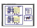
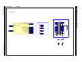
FIGURE A-3: LAN9252-2
SYNC1/LATCH1
18
SYNC0/LATCH0
34
A4/DIGIO12/GPI12/GPO12/MII_RXD0
27
A3/DIGIO11/GPI11/GPO11/MII_RXDV
26
A2/ALEHI/DIGIO10/GPI10/GPO10/LINKACTLED2/MII_LINKPOL
29
A1/ALELO/OE_EXT/MII_CLK25
25
A0/D15/AD15/DIGIO9/GPI9/GPO9/MII_RXER
33
D14/AD14/DIGIO8/GPI8/GPO8/MII_TXD3/TX_SHIFT1
15
D13/AD13/DIGIO7/GPI7/GPO7/MII_TXD2/TX_SHIFT0
16
D12/AD12/DIGIO6/GPI6/GPO6/MII_TXD1
21
D11/AD11/DIGIO5/GPI5/GPO5/MII_TXD0
22
D10/AD10/DIGIO4/GPI4/GPO4/MII_TXEN
23
D9/AD9/LATCH_IN/SCK
19
D8/AD8/DIGIO2/GPI2/GPO2/MII_MDIO
40
D7/AD7/DIGIO1/GPI1/GPO1/MII_MDC
39
D6/AD6/DIGIO0/GPI0/GPO0/MII_RXCLK
36
D5/AD5/OUTVALID/SCS#
50
D3/AD3/WD_TRIG/SIO3
35
D2/AD2/SOF/SIO2
12
D1/AD1/EOF/SO/SIO1
13
D0/AD0/WD_STATE/SI/SIO0
17
RD/RD_WR/DIGIO15/GPI15/GPO15/MII_RXD3
31
WR/ENB/DIGIO14/GPI14/GPO14/MII_RXD2
30
CS/DIGIO13/GPI13/GPO13/MII_RXD1
28
D4/AD4/DIGIO3/GPI3/GPO3/MII_LINK
49
U1B
DF40HC(4.0)-60DS-0.4V(51)
1
3
5
7
9
11
13
15
17
19
21
23
25
27
29
31
33
35
37
39
41
43
45
47
49
2
51
53
55
57
59
4
6
8
10
12
14
16
18
20
22
24
26
28
30
32
34
36
38
40
42
44
46
48
50
52
54
56
58
60
J3
D9_SCK
D5_SCS#
D1_SO
D0_SI
D9
SCK
D5
SCS#
D1
SO
D0
SI
3V3
3V3
RD
WR
CS
A4
A3
A2A1
[A0 not used]
D15
D14D13
D12
D10
D8
D11
D9
D7
D5
D3
D1D0
D2
D4
D6
SYNC1
SYNC0
IRQ
ERROR_LED
SCK SI
SO
SCS#
Orange
TP2
Black
TP3
3V3
LAN9252-PART2
B2B connector
Selection Jumpers for HBI or SPI
Test points place 100 mils apart
270R
0603
5%
R24
Br Grn
D2
"ERR"
External 3V3 if needed
"3V3" "GND"
'D9'
RD
WR
CS
SYNC1
SYNC0
A1
A2
A3
A4
D15
D14
D13
D12
D11
D10
D9_SCK
D8
D7
D6
D5_SCS#
D4
D3
D2
D1_SO
D0_SI
IRQ
1
1
1
2
3
HDR-2.54 Male 1x3
J4
1
1
1
2
3
HDR-2.54 Male 1x3
J5
1
1
1
2
3
HDR-2.54 Male 1x3
J6
1
1
1
2
3
HDR-2.54 Male 1x3
J7
Default Short (2-3)
Default Short (2-3)
Default Short (2-3)
Default Short (2-3)
'SCK'
'D5'
'SCS#'
'D1'
'SO'
'D0'
'SI'
1
1
2
HDR-2.54 Male 1x2
J8
1
1
2
HDR-2.54 Male 1x2
J9
'HBI'
'SPI'
Place J4,J5,J6 & J7 in closeby
DNP
TP5
DNP
TP6
Page is loading ...
Page is loading ...
-
 1
1
-
 2
2
-
 3
3
-
 4
4
-
 5
5
-
 6
6
-
 7
7
-
 8
8
-
 9
9
-
 10
10
-
 11
11
-
 12
12
-
 13
13
-
 14
14
-
 15
15
-
 16
16
-
 17
17
-
 18
18
-
 19
19
-
 20
20
-
 21
21
-
 22
22


Microchip Technology EVB-LAN9252-SPI Quick start guide
- Type
- Quick start guide
Ask a question and I''ll find the answer in the document
Finding information in a document is now easier with AI
Related papers
-
Microchip Technology MPLAB User manual
-
-
-
-
-
-
MICROCHIP EVB-LAN9252-ADD-ON User manual
-
-
-
Other documents
-
MICROCHIP VIDEO-DC-USXGMII FMC Kit User guide
-
-
-
-
-
-
-
DNP Supernova STS Installation guide
-
-