Page is loading ...

Hotwire
®
TDM SDSL
Termination Units
Models 8775 and 8785
User’s Guide
Document No. 8700-A2-GB25-10
February 2001

A
February 2001 8700-A2-GB25-10
Copyright © 2001 Paradyne Corporation.
All rights reserved.
Printed in U.S.A.
Notice
This publication is protected by federal copyright law. No part of this publication may be copied or distributed,
transmitted, transcribed, stored in a retrieval system, or translated into any human or computer language in any form or
by any means, electronic, mechanical, magnetic, manual or otherwise, or disclosed to third parties without the express
written permission of Paradyne Corporation, 8545 126th Ave. N., Largo, FL 33773.
Paradyne Corporation makes no representation or warranties with respect to the contents hereof and specifically
disclaims any implied warranties of merchantability or fitness for a particular purpose. Further, Paradyne Corporation
reserves the right to revise this publication and to make changes from time to time in the contents hereof without
obligation of Paradyne Corporation to notify any person of such revision or changes.
Changes and enhancements to the product and to the information herein will be documented and issued as a new
release to this manual.
Warranty, Sales, Service, and Training Information
Contact your local sales representative, service representative, or distributor directly for any help needed. For additional
information concerning warranty, sales, service, repair, installation, documentation, training, distributor locations, or
Paradyne worldwide office locations, use one of the following methods:
Internet:
Visit the Paradyne World Wide Web site at
www.paradyne.com
. (Be sure to register your warranty
at
www.paradyne.com/warranty
.)
Telephone:
Call our automated system to receive current information by fax or to speak with a company
representative.
— Within the U.S.A., call 1-800-870-2221
— Outside the U.S.A., call 1-727-530-2340
Document Feedback
We welcome your comments and suggestions about this document. Please mail them to Technical Publications,
Paradyne Corporation, 8545 126th Ave. N., Largo, FL 33773, or send e-mail to
userdoc@paradyne.com
. Include the
number and title of this document in your correspondence. Please include your name and phone number if you are
willing to provide additional clarification.
Trademarks
ACCULINK, COMSPHERE, FrameSaver, Hotwire, MVL, NextEDGE, OpenLane, and Performance Wizard are
registered trademarks of Paradyne Corporation. ReachDSL and TruePut are trademarks of Paradyne Corporation. All
other products and services mentioned herein are the trademarks, service marks, registered trademarks, or registered
service marks of their respective owners.
Regulatory and Safety Information
Refer to the appropriate Digital Subscriber Line Access Multiplexer (DSLAM) manual for all regulatory notices and
safety information.

8700-A2-GB25-10 February 2001
i
Contents
About This Guide
Document Purpose and Intended Audience . . . . . . . . . . . . . . . . . . . . v
Document Summary . . . . . . . . . . . . . . . . . . . . . . . . . . . . . . . . . . . . . . v
Product-Related Documents . . . . . . . . . . . . . . . . . . . . . . . . . . . . . . . . vi
1 About Hotwire 8775 and 8785 Termination Units
TDM SDSL Overview. . . . . . . . . . . . . . . . . . . . . . . . . . . . . . . . . . . . . . 1-1
Hotwire 8775 and 8785 Termination Unit Features . . . . . . . . . . . . . . . 1-2
Network Configuration . . . . . . . . . . . . . . . . . . . . . . . . . . . . . . . . . . . . . 1-3
SNMP Management Capabilities . . . . . . . . . . . . . . . . . . . . . . . . . . . . . 1-4
Management Information Base (MIB) Support . . . . . . . . . . . . . . . 1-4
SNMP Trap Support . . . . . . . . . . . . . . . . . . . . . . . . . . . . . . . . . . . 1-4
2 Using the Asynchronous Terminal Interface
User Interface Access . . . . . . . . . . . . . . . . . . . . . . . . . . . . . . . . . . . . . 2-1
Management Serial Port Settings . . . . . . . . . . . . . . . . . . . . . . . . . . . . 2-1
Logging In to the Hotwire DSLAM . . . . . . . . . . . . . . . . . . . . . . . . . . . . 2-2
Initiating an ATI Session . . . . . . . . . . . . . . . . . . . . . . . . . . . . . . . . . . . 2-2
Menu Hierarchy . . . . . . . . . . . . . . . . . . . . . . . . . . . . . . . . . . . . . . . . . . 2-4
Screen Work Areas . . . . . . . . . . . . . . . . . . . . . . . . . . . . . . . . . . . . . . . 2-5
Navigating the Screens . . . . . . . . . . . . . . . . . . . . . . . . . . . . . . . . . . . . 2-6
Keyboard Keys . . . . . . . . . . . . . . . . . . . . . . . . . . . . . . . . . . . . . . . 2-6
Function Keys . . . . . . . . . . . . . . . . . . . . . . . . . . . . . . . . . . . . . . . . 2-7
Switching Between Screen Areas . . . . . . . . . . . . . . . . . . . . . . . . . 2-8
Ending an ATI Session. . . . . . . . . . . . . . . . . . . . . . . . . . . . . . . . . . . . . 2-9
Exiting From the DSLAM Session . . . . . . . . . . . . . . . . . . . . . . . . . . . . 2-9

Contents
ii
February 2001 8700-A2-GB25-10
3 Initial Startup and Configuration
Overview . . . . . . . . . . . . . . . . . . . . . . . . . . . . . . . . . . . . . . . . . . . . . . . 3-1
Entering Identity Information . . . . . . . . . . . . . . . . . . . . . . . . . . . . . . . . 3-2
Configuring the Unit . . . . . . . . . . . . . . . . . . . . . . . . . . . . . . . . . . . . . . . 3-3
Current and Default Factory Configurations . . . . . . . . . . . . . . . . . 3-4
Configuration Loader. . . . . . . . . . . . . . . . . . . . . . . . . . . . . . . . . . . 3-5
Saving Configuration Options . . . . . . . . . . . . . . . . . . . . . . . . . . . . . . . 3-7
Downloading Firmware . . . . . . . . . . . . . . . . . . . . . . . . . . . . . . . . . . . . 3-8
AutoRate Feature. . . . . . . . . . . . . . . . . . . . . . . . . . . . . . . . . . . . . . . . . 3-10
Disabling AutoRate . . . . . . . . . . . . . . . . . . . . . . . . . . . . . . . . . . . . 3-10
Resetting AutoRate . . . . . . . . . . . . . . . . . . . . . . . . . . . . . . . . . . . . 3-11
Restoring Access to the User Interface . . . . . . . . . . . . . . . . . . . . . . . . 3-12
Resetting the Unit. . . . . . . . . . . . . . . . . . . . . . . . . . . . . . . . . . . . . . . . . 3-12
4 Monitoring the Unit
What to Monitor . . . . . . . . . . . . . . . . . . . . . . . . . . . . . . . . . . . . . . . . . . 4-1
Viewing System and Test Status . . . . . . . . . . . . . . . . . . . . . . . . . . . . . 4-2
Health and Status Messages. . . . . . . . . . . . . . . . . . . . . . . . . . . . . 4-3
Self-Test Results Messages . . . . . . . . . . . . . . . . . . . . . . . . . . . . . 4-5
Test Status Messages. . . . . . . . . . . . . . . . . . . . . . . . . . . . . . . . . . 4-5
Performance Statistics . . . . . . . . . . . . . . . . . . . . . . . . . . . . . . . . . . . . . 4-6
Viewing Network Error Statistics . . . . . . . . . . . . . . . . . . . . . . . . . . 4-6
Viewing Network Performance Statistics. . . . . . . . . . . . . . . . . . . . 4-8
Viewing Current Network Performance . . . . . . . . . . . . . . . . . . . . . 4-10
Viewing LED Status . . . . . . . . . . . . . . . . . . . . . . . . . . . . . . . . . . . . . . . 4-11
Front Panel LEDs. . . . . . . . . . . . . . . . . . . . . . . . . . . . . . . . . . . . . . . . . 4-12
5Testing
Accessing the Test Menu. . . . . . . . . . . . . . . . . . . . . . . . . . . . . . . . . . . 5-1
Running Network Tests . . . . . . . . . . . . . . . . . . . . . . . . . . . . . . . . . . . . 5-2
Line Loopback . . . . . . . . . . . . . . . . . . . . . . . . . . . . . . . . . . . . . . . . 5-3
Repeater Loopback . . . . . . . . . . . . . . . . . . . . . . . . . . . . . . . . . . . . 5-4
Remote Send Line Loopback . . . . . . . . . . . . . . . . . . . . . . . . . . . . 5-5
Send and Monitor 511 . . . . . . . . . . . . . . . . . . . . . . . . . . . . . . . . . . 5-6
Running SYNC Data Port Tests. . . . . . . . . . . . . . . . . . . . . . . . . . . . . . 5-7
Data Terminal Loopback . . . . . . . . . . . . . . . . . . . . . . . . . . . . . . . . 5-8
Data Channel Loopback . . . . . . . . . . . . . . . . . . . . . . . . . . . . . . . . 5-9
Send Remote Data Channel Loopback. . . . . . . . . . . . . . . . . . . . . 5-10

Contents
8700-A2-GB25-10 February 2001
iii
Device Tests . . . . . . . . . . . . . . . . . . . . . . . . . . . . . . . . . . . . . . . . . . . . 5-11
Lamp Test . . . . . . . . . . . . . . . . . . . . . . . . . . . . . . . . . . . . . . . . . . . 5-11
Ending an Active Test . . . . . . . . . . . . . . . . . . . . . . . . . . . . . . . . . . . . . 5-12
6 Messages and Troubleshooting
Overview . . . . . . . . . . . . . . . . . . . . . . . . . . . . . . . . . . . . . . . . . . . . . . . 6-1
Configuring SNMP Traps . . . . . . . . . . . . . . . . . . . . . . . . . . . . . . . . . . . 6-2
Device Messages. . . . . . . . . . . . . . . . . . . . . . . . . . . . . . . . . . . . . . . . . 6-3
Troubleshooting . . . . . . . . . . . . . . . . . . . . . . . . . . . . . . . . . . . . . . . . . . 6-5
7 Security
Overview . . . . . . . . . . . . . . . . . . . . . . . . . . . . . . . . . . . . . . . . . . . . . . . 7-1
ATI Access Levels . . . . . . . . . . . . . . . . . . . . . . . . . . . . . . . . . . . . . . . . 7-1
Creating a Login. . . . . . . . . . . . . . . . . . . . . . . . . . . . . . . . . . . . . . . . . . 7-2
Deleting a Login . . . . . . . . . . . . . . . . . . . . . . . . . . . . . . . . . . . . . . . . . . 7-3
Controlling SNMP Access . . . . . . . . . . . . . . . . . . . . . . . . . . . . . . . . . . 7-4
Assigning SNMP Community Names and Access Types . . . . . . . 7-4
Limiting SNMP Access through the IP Addresses of
the Managers. . . . . . . . . . . . . . . . . . . . . . . . . . . . . . . . . . . . . . . . . 7-4
8 IP Addressing
Selecting an IP Addressing Scheme . . . . . . . . . . . . . . . . . . . . . . . . . . 8-1
Configurations Not Running IP Conservative Software. . . . . . . . . 8-1
All Configurations. . . . . . . . . . . . . . . . . . . . . . . . . . . . . . . . . . . . . . 8-1
IP Addressing Example . . . . . . . . . . . . . . . . . . . . . . . . . . . . . . . . . . . . 8-2
A Configuration Options
Overview . . . . . . . . . . . . . . . . . . . . . . . . . . . . . . . . . . . . . . . . . . . . . . . A-1
Network Interface Options . . . . . . . . . . . . . . . . . . . . . . . . . . . . . . . . . . A-2
Synchronous Data Port Options. . . . . . . . . . . . . . . . . . . . . . . . . . . . . . A-4
Copy Ports Options . . . . . . . . . . . . . . . . . . . . . . . . . . . . . . . . . . . . . . . A-7
System Options . . . . . . . . . . . . . . . . . . . . . . . . . . . . . . . . . . . . . . . . . . A-8
Management and Communication Menu . . . . . . . . . . . . . . . . . . . . . . . A-9
Telnet Session Options . . . . . . . . . . . . . . . . . . . . . . . . . . . . . . . . . A-9
General SNMP Management Options. . . . . . . . . . . . . . . . . . . . . . A-11
SNMP NMS Security Options . . . . . . . . . . . . . . . . . . . . . . . . . . . . A-12
SNMP Trap Options. . . . . . . . . . . . . . . . . . . . . . . . . . . . . . . . . . . . A-13

Contents
iv
February 2001 8700-A2-GB25-10
B Standards Compliance for SNMP Traps
SNMP Traps. . . . . . . . . . . . . . . . . . . . . . . . . . . . . . . . . . . . . . . . . . . . . B-1
warmStart . . . . . . . . . . . . . . . . . . . . . . . . . . . . . . . . . . . . . . . . . . . B-1
authenticationFailure . . . . . . . . . . . . . . . . . . . . . . . . . . . . . . . . . . . B-1
linkUp and linkDown . . . . . . . . . . . . . . . . . . . . . . . . . . . . . . . . . . . B-2
Enterprise-Specific Traps. . . . . . . . . . . . . . . . . . . . . . . . . . . . . . . . . . . B-3
C Cables and Pin Assignments
Overview . . . . . . . . . . . . . . . . . . . . . . . . . . . . . . . . . . . . . . . . . . . . . . . C-1
50-Pin Telco Connector Pinouts for Model 8775 in a
Hotwire 8600 DSLAM. . . . . . . . . . . . . . . . . . . . . . . . . . . . . . . . . . . . . . C-2
50-Pin Telco Connector Pinouts for Model 8775 in a
Hotwire 8610 DSLAM. . . . . . . . . . . . . . . . . . . . . . . . . . . . . . . . . . . . . . C-3
50-Pin Telco Connector Pinouts for Model 8775 in a
Hotwire 8800 or 8810 DSLAM . . . . . . . . . . . . . . . . . . . . . . . . . . . . . . . C-4
50-Pin Telco Connector Pinouts for Model 8775 in a
Hotwire 8820 DSLAM. . . . . . . . . . . . . . . . . . . . . . . . . . . . . . . . . . . . . . C-5
50-Pin Telco Connector Pinouts for Model 8785 in a
Hotwire 8610 DSLAM. . . . . . . . . . . . . . . . . . . . . . . . . . . . . . . . . . . . . . C-6
50-Pin Telco Connector Pinouts for Model 8785 in a
Hotwire 8810 or 8820 DSLAM . . . . . . . . . . . . . . . . . . . . . . . . . . . . . . . C-7
100-Pin Plug-to-Four DB25 Receptacle EIA-530-A Cable. . . . . . . . . . C-8
100-Pin Plug-to-Four MS34 Receptacle V.35 Cable . . . . . . . . . . . . . . C-12
100-Pin Plug-to-Four DB37 Receptacle RS-449 Cable . . . . . . . . . . . . C-16
100-Pin Plug-to-Four DB15 Receptacle X.21 Cable . . . . . . . . . . . . . . C-20
100-Pin Plug-to-Four DB25 Receptacle EIA-530-A Crossover Cable . C-23
100-Pin Plug-to-Four MS34 Receptacle V.35 Crossover Cable . . . . . C-27
D Technical Specifications
Glossary
Index

8700-A2-GB25-10 February 2001
v
About This Guide
Document Purpose and Intended Audience
This guide contains information needed to set up, configure, and operate 4-port
Hotwire 8775 and 8785 Time Division Multiplexer Symmetric Digital Subscriber
Line (TDM SDSL) Termination Units. It is intended for installers and operators.
Document Summary
Section Description
Chapter 1,
About Hotwire 8775
and 8785 Termination Units
Describes the features and capabilities of the unit.
Chapter 2,
Using the
Asynchronous Terminal Interface
Provides instructions for accessing the user interface
and navigating the screens.
Chapter 3,
Initial Startup and
Configuration
Provides procedures for setting up the user interface
and configuring the unit.
Chapter 4,
Monitoring the Unit
Describes using the LEDs, status, and network
statistics to monitor the unit.
Chapter 5,
Te s ti n g
Provides information about available tests and test
setup.
Chapter 6,
Messages and
Troubleshooting
Provides information on SNMP traps, device
messages, and troubleshooting.
Chapter 7,
Security
Presents procedures for creating a login, setting the
effective access levels, and controlling SNMP
access.
Chapter 8,
IP Addressing
Provides information and examples regarding IP
addresses.
Appendix A,
Configuration
Options
Contains all configuration options, default settings,
and possible settings.
Appendix B,
Standards
Compliance for SNMP Traps
Contains SNMP trap compliance information.
Appendix C,
Cables and Pin
Assignments
Contains connector and interface information.

About This Guide
vi
February 2001 8700-A2-GB25-10
Product-Related Documents
Contact your sales or service representative to order additional product
documentation.
Paradyne documents are also available on the World Wide Web at
www.paradyne.com.
Select
Library
→
Technical Manuals.
Appendix D,
Technical
Specifications
Contains physical and regulatory specifications,
network and port interfaces, power consumption
values, and accessory part numbers.
Glossary
Defines acronyms and terms used in this document.
Index
Lists key terms, acronyms, concepts, and sections in
alphabetical order.
Section Description
Document Number Document Title
7970-A2-GB20
Hotwire TDM SDSL Standalone Termination Units,
Models 7974, 7975, 7976, 7984, 7985, and 7986,
User’sGuide
8000-A2-GB22
Hotwire Management Communications Controller (MCC)
Card, IP Conservative, User’s Guide
8000-A2-GB29
Hotwire Management Communications Controller (MCC)
Card User’s Guide
8610-A2-GN10
Hotwire 8610 DSLAM Installation Instructions
8620-A2-GN20
Hotwire 8620 GranDSLAM Installation Guide
8700-A2-GN15
Hotwire TDM SDSL Termination Units,
Models 8775 and 8785, Installation Instructions
8810-A2-GN11
Hotwire 8810 DSLAM Installation Instructions
8820-A2-GN20
Hotwire 8820 GranDSLAM Installation Guide

8700-A2-GB25-10 February 2001
1-1
1
About Hotwire 8775 and 8785
Termination Units
TDM SDSL Overview
Hotwire
®
Time Division Multiplexer Symmetric Digital Subscriber Line (TDM
SDSL) products maximize customer service areas by varying the DSL line rate.
This ensures symmetric DSL connectivity over a wide range of telephone line
distances and transmission line qualities.
Hotwire TDM SDSL products support router, multiplexer and PBX connections
with maximum loop reaches, as shown in Table 1-1, Maximum Loop Reach.
Hotwire 8775 and 8785 Termination Units are equipped with an automatic
configuration capability that reduces the installation process to a simple
plug-and-play mode. Simply connecting the units to the line automatically
configures the customer for the maximum data rate supported by the local loop.
Units can also be configured at fixed line speeds to achieve maximum distances.
Table 1-1. Maximum Loop Reach
Model
Transmission Rate
128 kbps 2.048 Mbps
8775 (over 2-wire loop) 8.8 km (29,000 ft) 4.5 km (14,700 ft)
8785 (over 4-wire loop) 10.7 km (35,000 ft) 6.0 km (19,600 ft)

1. About Hotwire 8775 and 8785 Termination Units
1-2
February 2001 8700-A2-GB25-10
Hotwire 8775 and 8785 Termination Unit Features
A 4-port Hotwire 8775 or 8785 TDM SDSL Termination Unit is a circuit board
mounted in a Hotwire 8600 or 8800 Series Digital Subscriber Line Access
Multiplexer (DSLAM). It is used to transport signals at high speeds over a
twisted-pair connection.
Hotwire 8775 and 8785 Termination Units offer these standard features:
AutoRate Capability.
Provides automatic configuration of line speed and data
rate upon connection.
Embedded Operations Channel (EOC).
Provides remote management via
SNMP or Telnet session capability over the TDM SDSL network.
Asynchronous Terminal Interface (ATI).
Provides a menu-driven
VT100-compatible terminal interface for configuring and managing the unit
locally or remotely by Telnet session.
Local Management.
Provides local management using the DSLAM's
management card with a:
— Terminal or PC via the Management Serial port of the DSLAM.
— Network Management System (NMS) via the Management MCC port of
the 8600 Series DSLAM or 10BaseT port of the 8800 Series DSLAM.
Remote Management.
Provides remote management:
— Out-of-band, using an external modem through the Management Serial
port of the DSLAM.
— Using SNMP or Telnet through the 10BaseT port or the Internal
Management Channel (IMC).
— Via Telnet over the EOC.
Alarm Indication.
Activates front panel LEDs.
Diagnostics.
Provides the capability to diagnose device and network
problems and perform tests, including digital loopbacks, pattern tests, and
self-test.
Device and Test Monitoring.
Provides the capability of tracking and
evaluating the unit's operation, including health and status, and error-rate
monitoring.

1. About Hotwire 8775 and 8785 Termination Units
8700-A2-GB25-10 February 2001
1-3
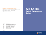
Network Configuration
Figure 1-1, Sample CO-to-CP Configuration, shows a network application using a
Hotwire 8775 or 8785 Termination Unit for access concentration in a central office
(CO). A frame relay switch and a router are connected to partner units through
the termination unit, supporting a host or router and frame relay encapsulated or
unframed data.
Figure 1-1. Sample CO-to-CP Configuration
Figure 1-2, Sample Campus Configuration, shows termination units used to
distribute T1 lines over a campus.
Figure 1-2. Sample Campus Configuration
Frame
Relay
Switch
Router
E1 Host
(Frame Relay
Encapsulated
Data)
99-16520
Router
(Frame Relay
Encapsulated
Data)
V.35
V.35
V.35
Router
2.048 Mb
over
DSL
V.35
V.35
V.35
87x5 Termination Unit
in 8600 DSLAM
CO Site
79x5
79x5
79x5
Customer Premises (CP)
99-16489
Multiple
DSL Lines
Multiplexer
Routers
G.703,
DSX-1,
or V.35
Building B Building A
DSX-1
T3

1. About Hotwire 8775 and 8785 Termination Units
1-4
February 2001 8700-A2-GB25-10
SNMP Management Capabilities
The termination unit supports SNMP Version 1, and can be managed by any
industry-standard SNMP manager and accessed using SNMP by external SNMP
managers.
Management Information Base (MIB) Support
For a detailed description of supported MIBs, visit Paradyne's Web site at
www.paradyne.com.
The following MIBs are supported:
MIB II (RFC 1213 and RFC 1573)
– Defines the general objects for use with a
network management protocol in TCP/IP internets and provides general
information about the unit. MIB II is backward-compatible with MIB I.
RS-232-Like MIB (RFC 1659)
– Defines objects for managing RS-232-type
interfaces (e.g., V.35, RS-422, RS-423, etc.) and supports the synchronous
data port on the DSU.
Enterprise MIB
– Supports
configuration, status, statistics, and tests.
SNMP Trap Support
The unit supports traps as defined in RFC 1215. They may include
variable-bindings specified in the following MIBs:
MIB II (RFC 1573)
– Defines the general objects for use with a network
management protocol in TCP/IP internets and provides general information
about the termination unit. MIB II is backward-compatible with MIB I.
Enterprise MIB
– Supports
configuration, status, statistics, and tests.
01-16521-01
V.35
8600 Series
DSLAM
Network
79x5
AC
INPUT
AC
48VDC CLASS 2 OR
LIMITED PWR SOURCE
RTN48V
AAB B
T5A
2
46
A
B
.
.
.
3
.
1
2
POSITION
STACK
ALM
A
IN
B
DC FUSES
T4A, MIN. 48V
5
DC PWR
FAN
OUT SERIAL
MCC 1
3
1
2
3
SYSTEM
OK
Alrm
Test
250V
SYSTEM
OK
Alrm
Test
1
2
3
4
G.703 ALRM
DSL PORT
LINK-UP
1
2
3
4
SYSTEM
OK
Alrm
Test
1
2
3
4
G.703 ALRM
DSL PORT
LINK-UP
SDSL
8715
1
2
3
4
Router
SNMP NMS
87x5
Ethernet
Interface
TDM SDSL
EOC
Data
Voice
Operation, Maintenance
and Provisioning Center
Ethernet
LAN
1
2
3
4
G.703 ALRM
DSL PORT
LINK-UP
1
2
3
4

8700-A2-GB25-10 February 2001
2-1
2
Using the Asynchronous
Terminal Interface
User Interface Access
You can communicate with the asynchronous terminal interface (ATI) using one of
the following methods:
Direct connection through the Management Serial port of the DSLAM (locally
or via an external modem).
Telnet session using a Network Management System (NMS) connected to a
LAN/WAN port on the DSLAM.
Telnet session through the Embedded Operations Channel (EOC).
NOTE:
Only one ATI session can be active at a time, and another user's session
cannot be forced to end. To automatically log out a user due to inactivity,
enable the Inactivity Timeout option. To enable the Inactivity Timeout option,
refer to Table A-5, Telnet Session Options, in Appendix A,
Configuration
Options
.
Security can limit ATI access several ways. To set up security or a login ID, refer to
Chapter 7,
Security
.
Management Serial Port Settings
Ensure that the device you connect communicates using these settings:
Data rate set to 9.6 kbps.
Character length set to 8.
Parity set to None.
Stop Bits set to 1.
Refer to the installation document for your DSLAM.

2. Using the Asynchronous Terminal Interface
2-2
February 2001 8700-A2-GB25-10
Logging In to the Hotwire DSLAM
You can log in to the Hotwire DSLAM system using either a local
VT100-compatible terminal or a remote Telnet connection.
After you enter your user ID and password, the system displays the Hotwire
Chassis Main Menu. See your management card documentation for information
about selecting the unit from the card selection screen.
Initiating an ATI Session
The Main Menu screen is displayed unless a login ID and password is required or
the ATI is already in use.
If the ATI is already in use, the message
connection refused
is sent to a
terminal attempting Telnet access.
If security is enabled and Telnet is used to access the terminal unit directly (you did
not log in through the MCC), the system prompts you for a login ID and password.
If you enter an invalid login ID and password three times, the Telnet session closes
or the terminal connection returns to an idle state. Refer to Chapter 7,
Security
.
Login Hotwire
Slot: 4 Model: 87x5
LOGIN
Login ID:
Enter Password:
--------------------------------------------------------------------------------
Ctrl-a to access these functions E
xit

2. Using the Asynchronous Terminal Interface
8700-A2-GB25-10 February 2001
2-3
After you enter a valid login ID and password, the Main Menu appears.
Entry to all of the termination unit's tasks begins at the Main Menu screen.
What appears on the screens depends on the:
Current configuration
– How your unit is currently configured.
Effective security access level
– An access level that is typically set by the
system administrator for each interface and each user.
Data selection criteria
– What you entered in previous screens.
main Access Level: Administrator Hotwire
Slot: 4 Model 87x5
MAIN MENU
Status
Test
Configuration
Control
--------------------------------------------------------------------------------
Ctrl-a to access these functions Exit
Screen
Area
Function Keys
and
Message Area
Select . . . To . . .
Status View system status, diagnostic test results, statistics, LED, and device
identity information.
Test Select, start, stop and cancel tests for the unit's interfaces.
Configuration Display and edit the configuration options.
Control Change the device identity, administer logins, download new firmware, or
initiate a power-up reset of the unit.

2. Using the Asynchronous Terminal Interface
2-4
February 2001 8700-A2-GB25-10
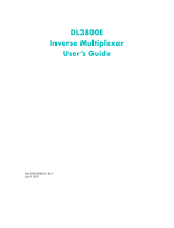
Menu Hierarchy
The following illustration shows the paths to the different ATI screens.
Main
Status Test
System and
Test Status
Performance
Statistics
Display
LEDs
Identity
Network
Error
Statistics
Network
Performance
Statistics
Configuration Control
Default
Factory
Configuration
Configuration
Loader
Current
Configuration
Network SYNC
Ports
Copy
Ports
System
Options
Management
and
Communication
Telnet
Session
General SNMP
Management
SNMP NMS
Security
SNMP
Traps
Change
Identity
Administer
Logins
Download
Code
Apply
Download
Reset
AutoRate
Network Tests SYNC Data
Port Tests
Device
Tests
Abort All
Tests
01-16296a-01
Reset
Device
Current
Network
Performance

2. Using the Asynchronous Terminal Interface
8700-A2-GB25-10 February 2001
2-5
Screen Work Areas
There are two user work areas:
Screen area
– This is the area above the dotted line that provides the menu
path, menus, and input fields.
The menu path appears as the first line on the screen. In this manual, the
menu path is presented as a menu selection sequence:
Main Menu
→
Configuration
→
Current Configuration
→
Network
Function keys and message area
– This is the area below the dotted line
that lists function keys specific to the screen, field value choices, and system
messages.
main/config/network Hotwire
Slot: 4 Model: 87x5
Port: 3
NETWORK INTERFACE OPTIONS
Margin Threshold: –3db
Excessive Error Rate Threshold: 1E–5
AutoRate Disable
DSL Line rate 2064
Circuit Identifier: Clear
--------------------------------------------------------------------------------
Ctrl-a to access these functions, ESC for previous menu MainMenu Exit
Save
Select: 1E–4, 1E–5, 1E–6, 1E–7, 1E–8, 1E–9 LOS at Net, Pt
n
Input
Fields
Function
Keys
Menu
Path
Field Value
Choices
System
Messages

2. Using the Asynchronous Terminal Interface
2-6
February 2001 8700-A2-GB25-10
Navigating the Screens
You can navigate the screens by:
Using keyboard keys
Using function keys
Switching between the two screen areas
Keyboard Keys
Use the following keyboard keys to navigate within the screen.
Procedure
To make a menu or field selection:
1. Press the Tab or right arrow key to position the cursor on a menu or field
selection. Each selection is highlighted as you press the key to move the
cursor from position to position.
2. Press Enter. The selected menu or screen appears.
3. Continue Steps 1 and 2 until you reach the screen you want.
Press . . . To . . .
Ctrl-a Move cursor between the screen area and the function keys area
below the dotted line at the bottom of the screen.
Esc Return to the previous screen.
Tab Move cursor to the next field on the screen.
Backspace Move cursor to the previous field on the screen.
Enter Accept entry or display valid options on the last row of the screen
when pressed before entering data or after entering invalid data.
Ctrl-k Tab backwards (move cursor one field to the left).
Spacebar Select the next valid value for the field.
Delete (Del) Delete character that the cursor is on.
Up Arrow or Ctrl-u Move cursor up one field within a column on the same screen.
Down Arrow or Ctrl-d Move cursor down one field within a column on the same screen.
Right Arrow or Ctrl-f Move cursor one character to the right if in edit mode.
Left Arrow or Ctrl-b Move cursor one character to the left if in edit mode.
Ctrl-l Redraw the screen display, clearing information typed in but not
yet entered.

2. Using the Asynchronous Terminal Interface
8700-A2-GB25-10 February 2001
2-7
The current setting or value appears to the right of the field name. You can enter
information into a selected field by:
Typing in the first letter(s) of a field value or command.
Switching from the screen area to the function key and message area below
the dotted line, and selecting or entering the designated function key.
If a field is blank and the Field Value Choices display valid selections, press the
spacebar; the first valid value for the field will appear in the field. Continue
pressing the spacebar to scroll through other valid values. Press Enter to select
the value.
Function Keys
All function keys located below the dotted line operate the same way (upper- or
lowercase) throughout the screens.
For the screen
function . . . Select . . . And press Enter to . . .
ClrFar F or f Clear far-end network statistics and refresh the screen.
ClrN
ear N or n Clear near-end network statistics and refresh the screen.
Delete L or l Delete data.
E
xit E or e Terminate the asynchronous terminal session.
MainMenu M or m Return to the Main Menu screen.
N
ew N or n Enter new data.
PgD
n D or d Display the next page, or group of entries.
PgUp U or u Display the previous page, or group of entries.
R
esetMon R or r Reset an active Monitor 511 test counter to zero.
S
ave S or s Save information.

2. Using the Asynchronous Terminal Interface
2-8
February 2001 8700-A2-GB25-10
Switching Between Screen Areas
Select Ctrl-a to switch between the two screen areas to perform all screen
functions.
Procedure
To access the function key and message area below the dotted line:
1. Press Ctrl-a to switch from the screen area to the function key and message
area below the dotted line.
2. Select either the function’s designated (underlined) character or press the Tab
key until you reach the desired function key.
Example:
To save the current options, type
s
or
S
(Save).
3. Press Enter. The function is performed.
4. To return to the screen area above the dotted line, press Ctrl-a again.
main/config/network Hotwire
Slot: 4 Model: 87x5
Port: 3
NETWORK INTERFACE OPTIONS
Margin Threshold: –3db
Excessive Error Rate Threshold: 1E–5
AutoRate Disable
DSL Line rate 2064
Circuit Identifier: Clear
--------------------------------------------------------------------------------
Ctrl-a to access these functions, ESC for previous menu MainMenu Exit
Save
/