Page is loading ...

T0440
Instruction manual • Bouwhandleiding • Bauanleitung • Instructions de montage
version: 16/07/2007 by FV
Electric powered semi-scale airplane
WARNING !
This R/C kit and the model you
will build is not a toy.
LET OP !
Deze bouwdoos van een
radiobestuurd model is geen
speelgoed.
ACHTUNG !
Dieser Bausatz eines
ferngesteurten Modells
ist kein Spielzeug.
ATTENTION !
Ce modèle R/C à assembler
n’est pas un jouet.

2 •
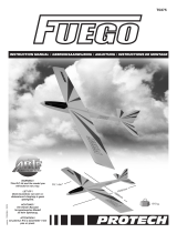
Specifi cations / Specifi caties /
Technische Daten / Spécifi cations
1. Fuselage
2. Wing
3. Vertical Fin
4. Elevator
5. Charger
6. Li-Po Battery
7. Adapter
8. Undercarriage
9. Propeller
10. Accessories
11. Transmitter
Clear building instructions
in English
1. Romp
2. Vleugel
3. Kielvlak
4. Hoogteroer
5. Lader
6. Li-Po accu
7. Adapter
8. Wielen
9. Propeller
10. Accesoires
11. Zender
Duidelijke handleiding in het
Nederlands
1. Rumpf
2. Flache
3. Seitenruder
4. Höhenruder
5. Seitenruder
6. Li-Po Accu
7. Netzgerät
8. Räder
9. Luftschraube
10. Accesoires
11. Sender
Illustrierte Bauanleitung auf
Deutsch
1. Fuselage
2. Aile
3. Dérive
4. Stabilisateur
5. Dérive
6. Li-Po batterie
7. Adaptateur
8. Train d’atterrissage
9. Hélice
10. Accesoires
11. Emetteur
Instructions de montage en
Français
Kit content / Inhoud van de bouwdoos /
Bausatzinhalt / Contenu de la boîte
Length: 960 mm
Wing span: 762 mm
Wing area: 15,3 dm
2
Wing loading: 28 g/dm
2
Power: Brushless
Flying weight: 430 g
Radio required: 4 ch progr. radio
w/ 3x B160 micro servos
Lengte: 960 mm
Spanwijdte: 762 mm
Vleugelopp.: 15,3 dm
2
Vleugelbel.: 28 g/dm
2
Aandrijving: Brushless
Vlieggewicht: 430 g
Radiobesturing: 4 kanaals progr.
radio met 3x B160 micro
servo’s
Länge: 960 mm
Spannweite: 762 mm
Tragfl ügelinhalt: 15,3 dm
2
Gesamtfl achen-
belastung: 28 g/dm
2
Antrieb: Brushless
Fluggewicht: 430 g
Funkfernsteuerung:
4 Kanal Progr. Steuerung
mit 3x B160 Micro Servos
Longueur: 960 mm
Envergure: 762 mm
Surface alaire: 15,3 dm
2
Charge alaire: 28 g/dm
2
Moteur: Brushless
Poids en vol: 430 g
Radio requise: Radio progr.
4 voies avec 3x B160 micro
servos
2
4
3
10
8
5
1
6
7
9
11

• 3
SPARE PARTS
SPARE PARTS
T0508.024-35M1
T0508.024-35M2
T0508.024-41M1
T0508.024-41M2 Avenger 4 Channel FM Transmitter
PRO.5-35 Micro RX FM - 35 MHz
PRO.5-40 Micro RX FM - 40 MHz
T0508.026 Adapter for Li-Po Charger
T0508.026-UK Adapter for Li-Po Charger UK version
T0440.025 Li-Po Matic 3 charger
PRO.E25 Apollo 25 A Brushless ESC T0440.002 Wing
T0440.004 Tail set T0440.005 Propeller
T0440.014 Motor cowling
T0440.015 Landing gear
T0508.019 B160 servo
T0440.023 Li-Po battery 11,1V 1250 mAh
T0440.003 Fuselage
T0440.009 Brushless Motor

4 •
Vor dem Versuch der ersten Inbetriebnahme muß die gesamte Betriebs- und Montageanleitung sorgfältig gelesen werden. Sie allein sind verantwortlich für den sicheren Betrieb Ihres
RC-Flugmodells. Bei Jugendlichen muß der Bau und Betrieb von einem Erwachsenen, der mit den Gegebenheiten und möglichen Gefahren eines RC-Flugmodells vertraut ist, verantwort-
lich überwacht werden.
Verwenden Sie immer nur passende, verpolungssichere Steckverbindungen. Alle stromführende Leitungen, Steckverbindungen, sowie die Antriebsbatterie, bei Selbstkonfektionierung
sind kurzschlußsicher zu isolieren. Kombinieren Sie niemals unterschiedliche, z.B. Blech- und Goldkontakte, da hier keine sichere Funktion gewährleistet ist.
Kurzschlüsse und Falschpolungen vermeiden.
Durch die hohe Energie der NC-Batterien besteht immer Explosions- und Brandgefahr.
Ein RC-Flugmodell kann nur funktionsfähig sein und den Erwartungen entsprechen, wenn es im Sinne der Bauanleitung sorgfältigste gebaut wurde. Nur ein vorsichtiger und überlegter
Umgang beim Betrieb schützt vor Personen- und Sachschäden. Modellfl iegen will gelernt sein. Bitte, wenden Sie sich dazu an erfahrene Modellfl ieger, an Vereine oder Modellfl ugschulen.
Ferner sei auf den Fachhandel und die einschlägige Fachpresse verwiesen. Am besten als Club-Mitglied auf zugelassenem Modellfl ugplatz fl iegen.
Gummiringe altern und werden mit der Zeit spröde und unbrauchbar. Sie müssen deshalb von Zeit zu Zeit gegen neue ausgetauscht werden. Überprüfen Sie vor jeder Anwendung den
verwendeten Gummi, durch Dehnversuche, auf seine Festigkeit.
Testläufe nur im Freien durchführen. Die starke Sogwirkung der Luftschraube und die schnell beschleunigte Lutftmenge kann in einem geschlossenen Raum zu Unfällen (Z.B durch
herabfallende Bilder, Ansaugen von Vorhängen) führen. Das Modell muß von einem Helfer festgehalten werden.
Sich niemals in oder vor der Umdrehungsfeld von Luftschrauben aufhalten! Es könnte sich doch einmal ein Teil davon lösen und mit hoher Geschwindigkeit und viel Energie wegfl iegen
und Sie oder Dritte treffen. Darauf achten daß kein sonstiger Gegenstand mit einer Luftschraube in Berührung kommt !
Die Blockierung der Luftschraube durch irgendwelche Teile, muß ausgeschlossen sein.
Vorsicht bei losen Kleidungsstücken wie Schals, weiten Hemden usw : sie werden vom Propellerstrahl angesaugt und können in den Luftschraubenkreis gelangen.
Steht ein Modell mit drehender Luftschraub Z.B. auf sandigem Grund, so werden Sand oder Schmutzpartikel angesaugt und herumgewirbelt, die u.ä. Augenschäden hervorrufen können.
Nötigenfalls Schutzbrille tragen.
Überprüfen Sie vor jeder Inbetriebnahme das Modell und alle an ihm gekoppelten Teile (z.B. Luftschrauben, Getriebe, RC-Teile usw) auf festen Sitz und mögliche Beschädigungen. Das
Modell darf erst nach Beseitigung aller Mängel in Betrieb genommen werden.
Vergewissen Sie sich, daß die verwendete Frequenz frei ist. Erst dann einschalten! Funkstörungen, verursacht durch Unbekannte können immer ohne Vorwarnung auftreten! Das Modell
ist dann steuerlos und unberechenbar! Fernlenkanlage nicht unbeaufsichtigt lassen, um ein Betätigen durch Dritte zu verhindern.
Motor nur einschalten, wenn nichts im Drehbereich der Luftschraube ist. Nicht versuchen die laufende Luftschraube anzuschalten. Motor mit Luftschraube nur im fest eingebauten
Zustand laufen lassen.
Die Fluglage des Modells muß während des gesamten Fluges immer eindeutig erkennbar sein, um immer ein sicheres Steuern und Ausweichen zu gewährleisten. Machen sich während
des Fluges Funktionsbeeinträchtigungen/Störungen bemerkbar, muß aus Sicherheitsgründen sofort die Landung eingeleitet werden. Sie haben anderen Luftfahrzeugen immer auszuwei-
chen. Start- und Landefl ächen müssen frei von Personen und sonstigen Hindernissen sein.
Dabei ist zu beachten, daß bei der Inbetriebnahme die Motorsteuerfunktion am Sender immer zuerst in AUS-Stellung gebracht wird. Danach Sender und dann erst Empfangsanlage ein-
schalten, um ein unkontrolliertes Anlaufen des Motors zu vermeiden. Gleichfalls gilt immer zuerst Empfangsanlage ausschalten, danach erst den Send er. Überprüfen Sie, daß die Rud er
sich entsprechend der Steuerknüppelbetätigung bewegen.
Mit diesen Hinweisen soll auf die vielfältigen Gefahren hingewiesen werden, die durch unsachgemäße und verantwortungslose Handhabung entstehen können. Richtig und gewissenhaft
betrieben ist Modellfl ug eine kreative, lehrreiche und erholsame Freizeitgestaltung.
Be sure to read right through the instructions covering assembly and operation of your model before you at tempt to operate it for the fi rst time. You are the only person who is respon-
sible for the safe operation of your radio-con trol led model. Young people should only be permitted to build and fl y these mod els under the instruction and su per vi sion of an adult who is
aware of the hazards involved in this activity.
Use only matching polarised connectors. All cables, connectors and the battery if home-as sem bled must be insulated to prevent short circuits. Never attempt to combine different types
of plug and socket - e.g. tin-plated and gold-plated types - as such combinations are bound to be un re li a ble.
NC batteries are capable of holding and releasing enormous amounts of energy, and as such represent a constant hazard of explosion and fi re.
We have no control over the way you build and operate your RC model aircraft, and for this rea son we are obliged to deny all liability for accidents. All we can do is point out the hazards
and make sure you are aware of them.
If you need help, please enlist the aid of an experienced modeller, a model club or enrol at a model fl ying training school. Model shops and the specialized model press are also good
sources of information. The best course is always to join a club and fl y at the approved model fl ying site.
Rubber bands deteriorate with age and become brittle. Replace them from time to time to maintain the safety and reliability of your model. Stretch all rubber bands before use to check
whether they are still strong enough for their purpose.
Motors should only be run in the open air! The powerful suction of the propeller and the volume of air which it accelerates can easily lead to accidents in enclosed spaces (e.g. pictures
falling down, curtains sucked into the propeller). The model must be held securely by an assistant at all times.
Keep well clear of the rotation fi eld of propellers - don't stand in line with it nor in front of it. You never know when some part may come loose and fl y off at high speed, hitting you or
anybody else in the vicinity. Never touch the revolving propeller with any object.
There must be no chance of any object getting in the way of the propeller and preventing it from ro tat ing.
Take care with loose clothing such as scarves, loose shirts etc. Flapping cloth can easily be sucked into the area of the propeller and then get tangled in it.
If you start your motor when the model is standing on loose or sandy ground, the propeller will suck up sand and dust and hurl it around and it could easily get in your eyes. Wear
protective goggles at such times.
Every time you intend to operate your model check carefully that the model itself and everything attached to it (e.g. pro pel ler, gearbox, RC components etc.) is in good condition and
undamaged. If you fi nd a fault do not fl y the model until you have corrected it.
Check whether your frequency is vacant before you switch on. Radio interference caused by unknown sources can occur at any time without warning. If this should happen, your model
will be uncontrollable and completely unpredictable. Never leave your radio control system unguarded, as other people might pick it up and try to use it.
Check that nothing is in the way of the propeller before you switch on the motor. Never attempt to stop the spinning propeller. Motors connected with a propeller should only be run
when installed securely.
lf you are to fl y your model safely and avoid problems, it is essential that you are aware of its po si tion and attitude throughout each fl ight - so don't let it fl y too far away! lf you detect a
control prob lem or in ter fer ence during a fl ight, immediately land the model to prevent a potential accident. Note that the transmitter throttle stick must be set to the OFF (motor stopped)
position BEFORE you switch on the power system. To avoid the motor starting unexpectedly, switch on the trans mit ter fi rst, then the receiving system. Use the reverse sequence when
switching off: receiver fi rst, then the transmitter. Check that the control surfaces move in the correct "sense" when you operate the sticks.
Please don't misunderstand the purpose of these notes. We only want to make you aware of the many dan gers and hazards which can arise if you lack knowledge and experience, or
work carelessly or irresponsibly. If you take reasonable care, model fl ying is a highly creative, instructive, enjoyable and relaxing leisure.
Wichtige Sicherheitshinweise
Important Safety Notes

6 •
Installing the Tail / Montage van de staart
Montierung von das Leitwerk / Montage de l’empennage
Apply some glue on the stab,
align the vertical fi n and glue the
pieces together.
Apply some glue in the fuselage
slot and slide the tail in place.
Check for collect alignment.
Breng wat lijm aan op de stabilo,
lijn het klielvlak uit en verlijm de
delen.
Breng lijm aan in de uitsparing
achteraan de romp en schuif de
staart in de romp. Controleer de
uitlijning.
Appliquez un peu de colle sur le
stabilisateur, installez et alignez
la dérive.
Appliquez un peu de colle dans
le logement du fuselage et
glissez l’empennage dans le
fuselage.
Contrôlez l’alignement de
l’ensemble.
Verkleben sie das Höhenleitwerk
und das Seitenleitwerk wie
abgebildet.
Verkleben Sie das Leitwerk in die
Rumpfschlitze.
Richten Sie das Leitwerk gerade
aus.
90o

• 7
Assembling the controls / Montage van de stuurstangen
Montieren von die Rudergestänge / Montage des commandes de l’empennage
Unscrew the linkage at the
servo side, slide the control
horn over the link, protrude the
control furface and click the re-
taining plastic on the other side
of the control surface.
Set the control surfaces and
servos in neutral position and
fasten the linkage on the servo.
Zet de stuurstangen los aan de
servo zijde, schuif de roerhoorn
over de stuurstang en bevestig
de roerhoorn op het roer. Monteer
de plastic clip aan de andere kant
van het roer.
Zet de roeren en servos in de
neutraalstand en sluit de stuur-
stangen terug aan.
Dévissez les vis des connec-
teurs sur les servos pour faciliter
l’installation des guignols sur les
commandes.
Raccordez le guignol sur la
commande. Positionnez et
pressez le guignol contre la
dérive pour la percer, installez la
contre-plaque sur l’autre côté.
Répétez les opérations pour
l’autre commande.
Placez les gouvernes en position
neutre, contrôlez que les servos
sont au neutre et ensuite serrez
les vis des connecteurs pour
fi xer les commandes.
Lösen Sie das Gestänge an die
Servo Seite, Schließen Sie die
Ruderhorn an das Gestänge an
und Montieren Sie die Ruder-
horner an die Rudern mittels die
mitgelieferde Clips.
Überprüfen Sie daß die Rudern
und Servos in Neutralstel-
lung sind und fi xieren Sie das
Gestänge

8 •
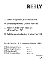
Glue the main undercarriage in
the fuselage slot.
Verlijm het onderstel in de sleuf
onderaan de romp.
Collez le train d’atterrissage dans
le logement.
Fix the propeller and apply the
decals.
Charge the battery
Connect the aileron servo to
channel 1 of the receiver. Check
the polarity!
Use the bolt to fi x the wing on
the fuselage.
Monteer de propeller en breng
de zelfklevers aan op het model.
Laad de batterij.
Sluit de rolroer servo aan op
kanaal 1 van de ontvanger
Gebruik de meegeleverde bout
om de vleugel op de romp te
monteren.
Fixez l’hélice.
Installez les autocollants.
Chargez l’accu.
Connectez le servo des ailer-
ons à la voie 1 du récepteur.
Respectez la polarité.
Fixez l’aile à l’aide de la vis
fournie.
Installing the main landing gear / Montage van het hoofdlandingsgestel
Montierung von das Fahrwerk / Montage du train d’atterrissage
Final steps / Eindmontage
Letzten Schritten / Etape fi nale
Verkleben Sie das Fahrwerk im
Rumpf.
Montieren Sie die Luftschraube.
Laden Sie die Accu.
Schließen Sie die Querruder
Servo am Kanal 1 an.
Schrauben Sie die Fläche auf
den Rumpf.

• 9
Charging the battery / Laden van de batterij/
Chargement de l’accu / Laden des Akkus
WARNING:
Do not leave battery unattented while charging!
OPGELET:
Laad de batterij nooit zonder toezicht!
ATTENTION:
Ne pas laisser l’accu sans surveillance pendant la charge !
ACHTUNG:
Akkus dürfen nur unter Aufsicht geladen werden!
Connect the 230V power supply
to the Li-Po charger. Connect the
power supply to a mains socket.
The RED led of the charger will turn
on. Connect the Li-Po batterypack
to the charger, the ORANGE led
will turn on. When the batterypack
is fully charged, the GREEN led
will turn on.
Sluit de 220V voeding aan op de
Li-Po lader. Steek de voeding in het
stopcontact. De RODE led van de
lader licht op. Sluit vervolgens het
Li-Po batterijpack aan op de lader.
De ORANJE led zal oplichten. Als
de batterij volledig geladen is zal de
GROENE led beginnen oplichten.
Connecter l'alimentation 220V
au chargeur Li-Po. Connecter
l'alimentation au secteur. La Led
ROUGE du chargeur s'allume.
Raccorder le pack d'accu au char-
geur. La Led ORANGE s' allume.
Quand l' accu est chargé, la Led
VERTE s'allume.
Verbinden Sie das 230 V Netzteil
mit dem Li-Po Ladegerät.
Stecken Sie das Netzteil in
eine geeignete Steckdose. Die
ROTE LED-Lampe leuchtet
nun. Verbinden Sie den LiPo-
Akku mit dem Ladegerät und
die ORANGENE LED-Lampe
leuchtet. Sobald der Akku
vollständig geladen ist geht die
GRÜNE LED-Lampe an

10 •
Operating for the fi rst time / Eerste aansluiting
Première prise en main / Erstmalige Inbetriebnahme
Set the throttle stick to the lowest position.
Plaats de gasstick in de laagste positie.
Placez le manche de gaz en position basse.
Schieben Sie den Gasknuppel in die
unterste position
Extend the antenna
Schuif de antenne uit
Déployez complètement l’antenne
Die Antenne vollständig ausfahren
Turn the transmitter “ON”
Zet de zender aan
Allumez l’émetteur
Schalten Sie den Sender ein
Test the electronics to be sure
operate properly. The model must
now be “trimmed” or fi ne tuned
for optimal performance. ALWAYS
turn the transmitter “ON” before
switching on the model.
Test of de electronika correct
functioneert. Het model moet nu
nog een fi jnafstelling krijgen voor
de beste resultaten.
Zet altijd eerst de zender aan
alvorens de schakelaar van het
model aan te zetten.
Testez l’équipement électronique
pour être sûre que tous fonctionne
correctement. L’hélicoptère peut
être maintenant réglé finement
pour obtenir les meilleures per-
formances.
Allumez TOUJOURS l’émetteur
en premier avant de allumer le
modèle.
Testen Sie die Elektronik, um
sicherzustellen, daß sie korrekt
funktioniert. Das Model muß nun
für eine optimale Funktionsweise
„getrimmt“ oder feinjustiert
werden.
Schalten Sie immer den Sender
ein, bevor Sie das Model
Einschalten.
Throttle stick (Left side)
Gasstick (Links)
Le manche de gaz (à Gauche)
Gasknuppel (Links)
MODE 2
Throttle stick (Right side)
Gasstick (Rechts)
Le manche de gaz (à Droite)
Gasknuppel (Rechts)
MODE 1
• Install the battery as shown.
• Plaats de batterij in de houder zoals afgebeeld.
• Installez l’accu comme montré.
• Bringen Sie der Akku an wie abgebildet.
WARNING:
DO NOT LEAVE THE BATTERY CONNECTED TO THE SPEED CONTROLLER when not using the model.
It will drain and damage the battery.
OPGELET: LAAT DE ACCU NIET AANGESLOTEN AAN DE SNELHEIDSREGELAAR gedurende langere periode.
De accu zal ontladen en beschadigd raken.
ATTENTION: NE PAS LAISSER L’ACCU CONNECTE AU VARIATEUR quand vous n’utilisez pas le modèle. L’accu
serait déchargé ou endommagé.
ACHTUNG: AKKU NICHT AM REGLER ANGESLOSSEN LASSEN!!!!
• Switch on the model
• Zet de schakelaar aan op het model
• Allumez le modèle
• Schalten Sie das Model ein.

• 11
Transmitter / Zender / Emetteur / Sender
- Transmitter antenna
- Zender antenne
- Antenne d’émetteur
- Senderantenne
- Throttle trim (adjust center position of throttle)
- Gas trim (regel de midden gas positie)
- Trim de gaz (Ajuste la position neutre)
- Trimmhebel Rotorschub
- Throttle/Rudder stick
(Throttle=Controls height - Rudder=heading)
- Gas/staartrotor stick
(Gas=stijgen/dalen - Staartrotor= richting)
- Stick Gaz/Direction
(Gaz= montée - Direction= rotation)
- Steuerknüppel Rotorschub-Gieren
- Rudder trim (adjust center position of rudder)
- Staartrotor trim (regel de middel staartrotor
positie)
- Trim de direction (Ajuste la position neutre)
- Trimmhebel Gieren
- Power switch (Power ON/OFF switch)
- Hoofdschakelaar (AAN/UIT)
- Interrupteur (Allume/éteint l’émetteur)
- EIN/AUS Schalter
- Simulator socket
- Simulator stekker
- Prise de simulateur
- Simulator Buchse
- Channel/Reverse switches
- Kanaal/ompool schakelaars
- Interrupteurs inverseur de voies
- Servoreverse Schalter
- Voltage indicator
- Spanningsindicator
- Témoins de charge des batteries
- Spannungsanzeige
- Elevator trim (adjust the center position)
- Elevator trim (regel de middel elevator positie)
- Trim du Pas (Ajuste la position neutre)
- Trimmhebel Nicken
- Aileron/Elevator stick
(Elevator=Forward/Back Aileron=Left/Right)
- Aileron/Elevator stick
(Elevator=voor/achter Aileron=links/rechts)
- Stick Aileron/Elevateur
(Elévateur=Avant/Arrière - Aileron=Gauche/Droite)
- Steuerknüppel Nicken-Rollen
- Aileron trim (adjust center position)
- Aileron trim (regel de middel aileron positie)
- Trim d’aileron (Ajuste la position neutre)
- Trimmhebel Rollen
- Charge socket
- Laadstekker
- Prise de charge
- Ladebuchse
- Throttle trim (adjust center position of throttle)
- Gas trim (regel de midden gas positie)
- Trim des gaz (Ajuste la position neutre)
- Trimmhebel Rotorschub
- Elevator/Rudder stick
(Elevator=Forward/back - Rudder=heading)
- Elevator/staartrotor stick
(Elevator= Voor/achteruit - Staartrotor= richting)
- Stick Elevateur/Direction
(Elevateur=Avant/Arrière - Direction= rotation)
- Steuerknüppel Nicken-Gieren
- Rudder trim (adjust center position of rudder)
- Staartrotor trim (regel de middel staartrotor
positie)
- Trim de direction (Ajuste la position neutre)
- Trimmhebel Gieren
- Elevator trim (adjust the center position)
- Elevator trim (regel de middel elevator positie)
- Trim du Pas (Ajuste la position neutre)
- Trimmhebel Nicken
- Aileron/Throttle stick
(Throttle=Up/down Aileron=Left/Right)
- Aileron/Gas stick
(Aileron=links/rechts - Gas= stijgen/dalen)
- Stick Aileron/Gaz
(Aileron=Gauche/Droite - Gaz= monter/descendre)
- Steuerknüppel Rollen-Motorschub
- Aileron trim (adjust center position)
- Aileron trim (regel de middel aileron positie)
- Trim d’aileron (Ajuste la position neutre)
- Trimmhebel Rollen
MODE 1
MODE 2
Place 8 pcs dry cells LR-6
in the battery box of the transmit-
ter.
Check the polarity!
Plaats 8 stuks Alkaline batterijen in
de batterijhouder van de zender.
Let op de juiste polariteit
Installer 8 piles Alkaline dans le
boîtier piles de l'émetteur.
Attention aux polarités
Setzen Sie 8 Stück AA Batterien
LR6 in das Batteriefach des Sen-
ders Ein.
Beachten Sie die richtige
Polarität
AIL
REV
NOR
ELE THR RUD
AIL
REV
NOR
ELE THR RUD
Mode 1
switch position
FOR CESSNA
ONLY
Mode 2
switch position
FOR CESSNA
ONLY

12 •
Using the speed controller:
• Switch ON the transmitter and check the throttle channel settings are +/-100% (for the computers radios). Set the throttle to closed or
brake position.
• Switch on the speed controller (or connect the power pack).
• You must hear a ‘beep’. Between switching on and the ‘beep’ the throttle stick must not be moved. If you do not hear a ‘beep’, switch off,
disconnect the power, wait for 5 seconds and repeat the procedure.
• If you do not hear ‘beep’ again, check the following:
o Is the servo connector plugged into throttle channel ?
o Is the throttle stick in “closed” position (off) ?
o Is the throttle channel in “normal” position?
• The position of “full throttle” will be adjusted automatically
• Warning: once the battery pack is connected, handle the model with extreme care! Ensure that you are well clear of the propeller at all
times. Rotating propellers are extremely dangerous!
• Always connect the motor battery pack just before fl ight and disconnect it immediately after landing the model.
• Warning: Even when the switch is “off” remember the battery pack may be connected, handle the model with extreme care and stay well
clear of the propeller!
Setting the brake:
• All controllers are supplied with brake on.
• How to change the brake
o Switch on the transmitter and move the stick to “full throttle”
o Connect the main power pack and turn on the receiver switch (if used)
o Wait 5 seconds, you will hear 4 beeps ( · · - · )
o Move the throttle stick to closed position
o You will hear 2 “beeps” to confi rm the brake is off. You will hear these two “beeps” after each controller activation.
o If you want to activate the brake, disconnect the battery pack and repeat the procedure.
Setting the Timing mode: (if you should use the speed controller in another model)
Timing monitor:
• The controllers have a timing monitor. The monitor gives information about actual timing setting.
• If you wait 5 seconds after activating the controller (after one or two “beeps”) you will hear set-up timing mode. It is possible to interrupt
this beeping any time by moving the throttle stick to forward.
• It is possible to change the timing on this generation of speed controllers.
• All controllers are supplied in Timing mode 1 You can change the timing for optimal effi ciency for your type of brushless motor.
Timing mode 1 – (2-5 degrees) optimum timing for 2-pole motors
Timing mode 2 – (18 degrees) optimum timing for 6-pole motors and 4-pole motors.
• How to change the timing:
o Switch on the transmitter and move the stick to full throttle
o Connect the main power pack and turn on the receiver switch (if used)
o Wait 5 seconds, you will hear 4 beeps ( · · - · )
o Wait another 5 seconds
o You will hear 5 times a single “beep” – mode 1 ( · , · , · , · , · )
o 5 time two “beeps” – mode 2 ( ·· , ·· , ·· , ·· , ·· )
o Set the timing mode by moving the throttle stick to the “closed” position between the 1
st
and 5
th
“beep” of the desired timing mode.
o The new timing mode will be confi rmed by a single “beep” (with brake on) or double “beep” (with brake off)
o The timing mode is now saved and will not change after disconnecting the battery pack.
o If you want to change the timing mode again, disconnect the motor battery pack and repeat the procedure.
Cut off setting:
• The speed controller will turn-off the motor when the main power pack voltage falls under 5V or reaches 0,7 V/cell. It depends on
which occurs fi rst. Soft power cut off except if you have the brake turned on.
Notes about operation and Warranty:
• Reversing the motor direction is achieved by the exchanging the position of any two wires connected to the motor.
• Do not exceed the 10 cells or 4-5 servos when using BEC.
• Temperature overload protection is built into the speed controller, it turns off the motor when the temperature reaches 230°F/110°C.
• These speed controllers are equipped with protection functions that take care of correct start and operation of the motor across the
whole range of RPM, current and voltage.
• Do not connect the speed controller to just ‘any’ kind of power source. Take care to ensure the right polarity of NiCd, NiMH or Lithium
power packs only.
• Respect the polarity of your battery while connecting the speed controller, the speed controller will be severely damaged if the polarity is
incorrect and WILL NOT be covered under warranty.
Electronic speed controller operation

16 •
Adjustments / Afregelingen
Correct
Juist
The correct adjustment of your aircraft is very important. Check carefully
wheather all control surfaces move in the correct direction. To check
all functions, you should be standing behind your plane. If the control
surfaces do not move in the correct direction, you can reverse the servo
direction on your transmitter.
It is very important that you check the position of the CG. Put a mark
on the underside of the wing (left and right) at 60 mm from the leading
edge and place the model on a table whit its nose towards you. Place
one fi nger on each mark and lift the plane. There are special supports
available in your local modelshop to help checking the CG. Always
check the CG with an empty fuel tank.
Check the CG each time before you fl y your model, a bad CG will
give serious fl ying problems.
Het afregelen van uw vliegtuig is zeer belangrijk. Kijk goed na of alle
stuurbevelen juist uitgevoerd worden. Om te controleren of alles juist
functioneert, gaat u achter het vliegtuig staan. Mocht een stuurcom-
mando de foutieve richting uitdraaien, dan kan deze draairichting op de
radiobesturing aangepast worden door de draairichting van de servo
om te keren.
Uiterst belangrijk is de juiste ligging van het zwaartepunt. Plaats aan
de onderkant van de vleugel een merkteken ( zowel op de linker- als
de rechtervleugel) op 60 mm van de aanvalsboord, en zet het model
op een tafel met de neus naar u gericht. Plaats uw wijsvingers langs
beide zijden van de romp op het merkteken zodat het model op de
vingertoppen gaat balanceren. Er bestaan in de vakhandel eveneens
speciale steunen voor het controleren van het zwaartepunt. Het con-
troleren van het zwaartepunt dient altijd met lege tank te gebeuren.
Controleer het zwaartepunt voor elke vlucht, een verkeerde lig-
ging van het zwaartepunt kan ernstige vliegproblemen veroor-
zaken.
Als het model teveel met de neus naar beneden hangt , dan dient u de
componenten van de besturing in het model naar achter te verplaat-
sen, te beginnen met de ontvangeraccu. Bij belangrijke afwijking kan u
eventueel lood bijplaatsen, er voor zorgend dat dit goed is vastgelijmd.
Als het model lichtjes met de neus naar beneden hangt, ligt het zwaar-
tepunt op de juiste plaats.
If the rear of the plane drops, there is not enough load on the nose. Try
to move the battery and/or the receiver forward in the fuselage. If it is
necessary, add small lead under the tank for example.
If the nose of the plane drops, begin by moving the battery towards the
rear of the model. If this is still not enough to get the model level then
you must put a small amount of lead on the rear of the fuselage ( make
sure the lead is securely fi xed into place)
The model is in balance when the nose of the model is (almost) level.
Als het model teveel met de neus naar boven hangt, dan dient u de
componenten van de besturing naar voor te verplaatsen , te beginnen
met de ontvangeraccu. Bij belangrijke afwijking kan u eventueel lood
bijplaatsen, er voor zorgend dat dit goed is vastgelijmd. Als het model
lichtjes met de neus naar beneden hangt, ligt het zwaartepunt op de
juiste plaats.
Wrong
Fout
Wrong
Fout

18 •
You stand behind the aircraft
You move the rudder stick to the left Rudder and nosewheel must go to the left
You move the rudder stick to the right Rudder and nosewheel must go to the right
You pull back your elevator stick The elevator panel will move upwards
You push forward your elevator stick The elevator panel will move downwards.
You move the aileron stick to the left The left aileron will go upwards,
the right aileron will go downwards
You move the aileron stick to the right The left aileron will go downwards,
the right aileron will go upwards
You pull back the throttle stick The motor stops
You push forward the throttle stick The motor is at full power
U staat achter het vliegtuig
U stuurt met uw stuurknuppel voor het richtingsroer naar links Stuurvlak van het richtingsroer en neuswiel zwenkt links
U stuurt met uw stuurknuppel voor het richtingsroer naar rechts Stuurvlak van het richtingsroer en neuswiel zwenkt rechts
U trekt stuurknuppel van het hoogteroer naar u toe Stuurvlak van het hoogteroer gaat naar boven
U duwt de stuurknuppel van het hoogteroer van u weg Stuurvlak van het hoogteroer gaat naar beneden
U stuurt met uw stuurknuppel van de rolroeren naar links Links rolroer gaat naar boven, rechts rolroer naar beneden
U stuurt met uw stuurknupperl van de rolroeren naar reachts Rechts rolroer gaat naar boven, links rolroer naar beneden
U trekt de stuurknuppel van het gas naar beneden De motor stopt
U duwt de stuurknuppel van het gas naar boven De motor draait op volle toeren
Vous vous trouvez derrière l’avion
Vous bougez le stick de direction à gauche Gouverne et roue avant sont à gauche
Vous bougez le stick de direction à droite Gouverne et roue avant sont à droite
Vous tirez sur le stick de profondeur La gouverne de profondeur monte
Vous poussez sur le stick de profondeur La gouverne de profondeur descend
Vous bougez le stick d’ailerons à gauche L’aileron gauche monte et l’aileron droit descend
Vous bougez le stick d’ailerons à droite L’aileron gauche descend et l’aileron droit monte
Vous tirez sur le stick de gas Le moteur s’arrête
Vous poussez sur le stick de gas Le moteur tourne à plein régime
Adjustments / Afregelingen

• 19
OK
Flying instructions / Vlieginstructies
Fluganleitung / Instructions pour le vol
• Choose an open fl ying area away
from buildings, roads, power
lines, trees and water.
• Kies een open plaats voor het
vliegen, verwijdert van gebou-
wen, wegen, elektriciteitskabels,
bomen en water.
• Wählen Sie einen offene Gelän-
de weg von den Gebäuden, von
Straßen, von Hochspannung,
von Leitungen, Bäumen und vom
Wasser.
• Choisissez un endroit bien dé-
gagé et PAS à proximité de bâ-
timents, routes, arbres, ligne à
haute tension et plan d’eau.
• Always fully extent the transmit-
ter antenna.
• Before take off you should check
the direction of the wind.
• Beginning pilots should choose a
day with little or no wind.
• Trek de antenne volledig uit.
• Controleer eerst de richting van
de wind voor u begint te vliegen.
• Beginnende piloten kiezen best
een dag zonder of met weinig
wind.
• Die Antenne völlig ausziehen.
• Vor Sie mit das Fliegen anfän-
gen sollten Sie die Richtung des
Winds überprüfen.
• Einen anfangende Pilot soll einen
Tag mit wenigem oder keinem
Wind wählen.
• Toujours sortir l’antenne complè-
tement.
• Avant le décollage vérifi er la di-
rection du vent.
• Les pilotes débutants choisiront
un jour sans ou avec peu de
vent.

20 •
Flying instructions / Vlieginstructies
Fluganleitung / Instructions pour le vol
PRECAUTION DURING FLYING
• The plane should fl y in a cone
shape no more than 100 feet
away from the pilot.
• Always fl y the plane in front of
you. Never let it fl y directly over-
head because you could easily
loose your perception of how the
plane is fl ying.
VOORZORGSMAATREGELINGEN
TIJDENS HET VLIEGEN
• Het model moet steeds in een
circelvormige beweging vliegen
op niet meer dan 30 meter van de
piloot.
• Laat het model steeds voor jou
vliegen. Nooit over je hoofd heen
vliegen omdat dit makkelijk voor
verwarring kan zorgen bij het
waarnemen van hoe het model
nu vliegt.
VORSORGEMASSNAHMEN WÄH-
REND DES FLIEGEN
• Das Flugzeug sollte nicht mehr
als 30 Meter weg fl iegen vom Pi-
lot.
• Fliegen Sie immer das Flugzeug
in Gesichtsfeld. Lassen Sie es nie
direkt über dein Kopf fl iegen, weil
Sie einfach Ihre Vorstellung ver-
lieren können wie das Flugzeug
fl iegt.
PRECAUTION PENDANT LE VOL
• Votre avion doit évoluer dans un
cône de ±30 mètres face à vous.
• Toujours garder l’avion face à
vous, ne jamais le laisser passer
au-dessus de vous parce que
vous perdriez toute perception
de la façon dont l’avion évolue
(monte / descend).
LANDING THE PLANE:
• When the plane is about 30 feet
above the ground turn it into the
wind and lower the speed and
than cut off the motor to land.
LANDEN VAN HET MODEL:
• Als het vliegtuig op ongeveer
10m hoogte vliegt draai dan in
de wind, verminder de gas en zet
dan de motor uit zodat u kan lan-
den.
LANDUNG:
• Wenn das Flugzeug ungefähr 10
Meter über dem Grund ist müs-
sen Sie es zu den Wind drehen,
verringeren Sie den Gas und
schalten Sie den Motor ab für die
landung.
ATTERRISSAGE:
• Amorcez votre descente, virez
pour être avec le nez dans le vent.
A une altitude de ±10 m réduisez
puis coupez le moteur pour l’at-
terrissage.

• 21
Flying instructions / Vlieginstructies
Fluganleitung / Instructions pour le vol
INTERFERENCE
• Before fl ying you should always
check to see if other planes in the
area are on the same frequency,
as this will cause transmitter in-
terference between the planes
and cause accidents.
ZENDERSTORINGEN
• Voor het vliegen, moet U steeds
kontroleren of er andere model-
len in de buurt niet dezelfde fre-
quentie hebben, daar dit zender-
storingen kan geven tussen de
verschillende modellen en onge-
lukken kan veroorzaken.
STÖRUNG
• Vor das Fliegen sollte Sie immer
die Frequenz überprüfen, um zu
sehen, ob andere Piloten im Be-
reich auf der gleichen Frequenz
sind, da dies Störungen zwischen
den Flugzeugen gibt und Unfälle
verursachen kann.
INTERFERENCE
• Avant de voler, vous devez tou-
jours vérifi er si d’autres pilotes
n’utilisent pas la même fréquence
que vous, sans cette précaution il
y aura des interférences entre les
avions qui occasionneront une
perte de contrôle et un “crash“.
WARNING
• Always stay away from trees, tall
buildings and elevated land be-
cause there is a lot of turbulence.
The plane is a lightweight and will
be carried away in the turbulence
and will be uncontrollable and
may be lost.
WAARSCHUWING
• Nooit in de nabijheid van bomen,
hoge gebouwen en golvend land
vliegen daar hier veel turbulentie
is. Het model is een lichtgewicht
en zal meegenomen worden door
de turbulentie, het zal onbestuur-
baar zijn en wegwaaien.
WARNUNG
• Bleiben Sie immer weg von den
Bäumen, von den hohen Gebäu-
den und von erhöhtem Land, weil
es eine menge Turbulenz gibt.
Das Flugzeug ist ein Leichtge-
wichtler und wird in der Turbulenz
genommen, ist unkontrollierbar
und kann absturzen.
ATTENTION
• Ne jamais voler à proximité d’ar-
bres, bâtiments, collines à cause
des turbulences. L’avion étant
très léger, il serait malmené, ren-
du incontrôlable et probablement
emmené très loin.

22 •
SAFETY INFORMATION and HANDLING PRECAUTIONS for lipo battery
Introduction: Modern Lithium Polymer batteries (LiPo, Li-Poly) are a preferred source of power for fl ying models because of their ability to store and
deliver large amounts of energy from light-weight packs. Performance wise, these new batteries have much more in common with model aircraft fuel
than with any previous battery technology and they deserve similar respect: For safe handling it is useful to Think of Lithium Polymer Batteries as
Fuel.
Treated with respect in knowledgeable hands, Lithium Polymer batteries have been proven world-wide to be a controllable, practical and enjoyable
power source for model aviation.
What can go wrong:
Fire can be caused by: ‘Overcharging’ (wrong charger or charger setting, unbalanced battery load, charger fouled by poor power supply), charging
a damaged cell or pack and short circuit (including crash damage).
Cells or packs can be damaged by: Over discharging (running ‘too fl at’ and/or too hot, discharging an unbalanced battery load), short circuit and
crash damage.
The defi nitions of ‘overcharging’ and ‘too fl at’ are detailed in the do’s and don’ts section overleaf.
With the exception of a very small number of fi res that have resulted directly from crash damage at the fl ying fi eld, fi res have almost always occurred
during charging. These fi res have been almost exclusively permitted by avoidable human error. Therefore the main purpose of this information is:
A. To provide information that can help you actively avoid a dangerous charging situation.
B. To provide some standard precautions to limit loss or injury in case a fi re results anyway
Some Lithium Polymer Jargon Explained.
• 3s1p - means a battery pack containing 3 cells in series, 1 cell in parallel. 5s2p means a battery
pack containing 5 cells in series, 2 cells in parallel and so on.
• Cells in series “s” add to the Voltage (V). For every “s” add 3.7 Volts (nominal). Parallel cells “p”
add to the capacity of the battery in mAh. A “2p” pack made from 2500mAh cells will become a
5000mAh pack, “3p” 7500mAh and so on. The choice of single or multiple “p” packs is a feature
of LiPo (for NiCd and NiMH packs the term “p” is redundant as these packs are invariably “1p”)
• For LiPo packs made with the identical kind of cells, a 3s2p pack can deliver twice the current for
roughly the same duration as a 3s1p pack, or the same current for roughly twice the length time.
• In our 3s1p / 3s2p example, note that the 3s2p will be about twice the weight and size. For maximum power-to-weight performance in a model,
we would generally choose the 3s2p only when the required current approaches or exceeds the discharge “C” rating of the 3s1p.
• “C” is a 1000:1 ratio of the capacity of a cell or pack in mAh to a given current in Amps. It is normally used to defi ne maximum current-handling
capabilities for charging (e.g.1C or 2C) and discharging. A large “C rating” for discharge permits high currents from smaller packs, for instance
a 20C continuous rated 5000mAh pack is able to deliver 100 Amps continuously. In this instance, 20C constant should be seen as the maxi-
mum “full throttle” that can be applied ongoing before damage to the pack will be inevitable. Like running a sports car at full throttle all the time,
habitually running a Lipo pack at its maximum C rating is not good practice.
• 3.7V is the nominal voltage for LiPo chemistry. The actual voltage per series cell will increase when fully charged to about 4.2V and decrease to
3.0Vat full permitted discharge.
• 4.25V is a maximum, charging at higher voltage is dangerous. 3.0V is a minimum, continuing to draw operating current (Amps) when the cell
has reached 3.0V will cause rapid overheating and damage.
• For charging set-up we are principally concerned with the number of cells in SERIES. A 3s2p pack MUST be charged as a "3-cell" lithium poly-
mer (LiPo) pack, sometimes shown as a 11.1V pack (= 3 x 3.7V). We should normally limit the current during charging to a maximum of 1C, for
instance 5 Amps for a 5000mAh pack. An appropriate LiPo charger will normally prevent overcharging if this data is entered correctly.
• The new 20C chemistry can be charged at 2C and above for the fi rst 90% of its capacity, given proper supervision and / or an approprite LiPo
fast charger. For most LiPo chargers on the market, setting the charger to a 1C charge rate should be regarded as good practice.

• 23
SAFETY INFORMATION and HANDLING PRECAUTIONS for lipo battery
To actively prevent a fi re:
Lithum Polymer Do’s
Do Always use a correctly specifi ed Lithium Polymer charger [mandatory]
Do Always double-check that your multi-function charger is set in LiPo mode [extremely important]
Do ensure that your charger has a clean power supply such as a car battery that is not itself on charge
Do Always set the charger to the total series cell count “s” of your pack (or packs if charging in series)
Do read the battery label to confi rm the cell count for charging shown e.g. “charge as 3 cell”.
Do handle and transport carefully to avoid piercing, deformation or short circuit with other objects.
Do Disconnect batteries fully from ESC’s with BEC to prevent slow over-discharge.
Do ensure connectors are insulated correctly to prevent short circuit in handling or storage
Do always check that batteries are physically and electrically undamaged before charge or discharge
Lithum Polymer Don’ts
Don’t ever allow charging to continue above 4.25V per “s” series cell [defi nition of overcharging]
Don’t confuse the total number of actual cells in a pack (e.g. 6 for 3s2p) with the series cell count (3 for 3s2p)
Don’t set the charge current limit above 1C unless you have special equipment available and supervise the process fully. 1C = 3.2Amps for a 3200mAh
pack, 0.83Amps for an 830mAh pack and so on. Chose an available charger setting at or below the 1C value for your pack.
Don’t charge dissimilar or un-matched packs in series or with any difference in cell type, cell capacity, pack capacity or charge state (+/- 0.03V per
cell). If in any doubt, charge separately.
Don’t permit your pack to be discharged below 3.0V per cell (hint, use monitoring and timing or a Lithium-safe ESC, land immediately in case of
noticeable power drop, over-discharge = overheating/damage)
Don’t expose batteries to intense heat or prolonged exposure to elevated temperature
Don’t charge any pack containing one or more damaged or swollen cell.
Don’t continue charging if any part of the pack is getting warm (Lipo packs should charge cool)
Don’t charge any pack that is undervoltage after recovery (under 3.0V per series cell)
Don’t charge batteries unattended, always remain alert and monitor the charging process
To limit the consequences of a potential fi re hazard:
Charge in an isolated area away from fl ammables and valuables and avoid charging batteries in the model. If you decide to charge in the vicinity of
other property, equip your charging location with a dry extinguisher or fi re blanket. Never charge in a moving vehicle where the dangers of fi re and
smoke can be compounded by the risk of a road accident. If the battery is crashed in a model, or gets warm during charging place the battery in
an open space for observation, never directly into a vehicle, clubhouse, garage or home. If at any time you observe a cell or pack that has started
to balloon or swell up, place in a safe area for observation. If swelling occurs while charging, disconnect immediately and place in a safe place for
observation. If the wire leads accidentally short out place battery in a safe place and observe for 15 minutes. If you determine that the battery should
be disposed of, discharge it slowly to dead fl at before throwing away or recycling so it does not present a short-circuit danger to the waste disposal
system. Use a light bulb or immerse in salt water to discharge slowly.
Please note: Terms of use. The purpose of this document is to warn you of the safety considerations surrounding batteries of this type so that you
are better informed when making decisions and taking precautions concerning their use. These batteries are intended for RC fl ight only, no other
use is approved. Because RC modelling invariably requires decisions about preparation and deployment to pass beyond our control (and that of our
retailers or agents) your decision to use PROTECH product incorporates your agreement that you have read and understood the safety precautions
printed here and on each battery pack, and that you agree to accept full responsibility for any injury, loss or damage resulting from all circumstances
surrounding your use or misuse of this product. You are also responsible for inspecting and detecting any signs of damage or defect before and after
fl ight and prior to charging and to discontinue use immediately if any such issue arises. If you do not agree to these terms of use, you are under no
obligation to proceed.

On request
Olen, July 16th 2007
Declaration of conformity EC-R&TTE
Product: Model aircraft with 4CH radio transmitter AVENGER
Intended Purpose: Radio equipment for remote controlling of models
Equipment class: 2
Complies with the essential requirements of chapter 3 and the other relevant provisions of the
FTEG (Article 3 of the R&TTE directive), when used for its intended purpose
Harmonised standards applied
Stefan Engelen
CEO
PROTECH is a registered trademark of
PRO MODELS BVBA - GEELSEWEG 80 - 2250 OLEN - BELGIUM
Tel: + 32 14 25 92 83 email: [email protected]

Visit our website
www.protech.be
PROTECH® is a registered trademark
Geelseweg 80 • B-2250 OLEN • Belgium
Tel. +32 (0)14-25 92 83 • E-mail: [email protected]
www.protech.be
/