Page is loading ...

1
DESCRIPTION
The OMEGA
®
SV100 and SV200 Series Solenoid Valves for liquids and gases
cover most industrial and laboratory applications. The valves are available in
sizes ranging from 1/4" to 2" NPT, with CV’s as high as 38. OMEGA also offers
general purpose 2, 3, and 4-way valves made of brass or stainless steel, and
specialty valves for hot water and steam applications.
WARNING: When using solenoid valves, the possibility of creating damaging
water hammers exists. Install proper surge suppressors on the line in front of
susceptible electronic pressure, flow, and pH equipment.
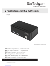
TWO-WAY VALVES
Two-way Normally Closed Valves
(121-128, 201-207, 221-225, 231-235, 281-287)
When the valve is de-energized, flow through the valve is prevented. When the
valve is energized, flow through the valve occurs.
Figure 1. Two-way Valves
Two-way Normally Open Valves
(131-133, 211-217, 291-295)
When the valve is de-energized, flow through the valve occurs. When the valve
energizes, flow through the valve is prevented.
Anti-Water Hammer Solenoid Valves (SV283-287, 291-295)
The closing time on these valves can be adjusted by a 4-position selector.
Position 1 allows fast closing, while 4 allows slowest closing setting. SV281 and
SV282 are anti-water hammer valves, but they do not have this adjustment for
varying the closing time. Normally Closed anti-water hammer valves SV283-287
are supplied with a manual override.
SV100 and SV200 SERIES
Solenoid Valves
INSTRUCTION
SHEET
M1103/0308
Shop online at: omega.com e-mail: [email protected]
For latest product manuals: omegamanual.info

SV100 and SV200 Solenoid Valves
2
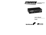
THREE-WAY VALVES
Three-way Normally Closed Valves (SV241, 242, 261)
A three-way Normally Closed valve has three ports labeled 1, 2, and 3. When
de-energized, no flow occurs from Port 1, but there is flow from Port 2 to Port 3.
When energized, flow occurs from Port 1 to 2, but no flow occurs from Port 3.
Normally three-way valves are used to control larger pneumatically-activated
valves. When controlling pneumatic-activated valves, Port 1 is connected to the
pressure source, Port 2 is connected to the cylinder controlling the pneumatic
activation, and Port 3 is the exhaust port vented to the room. Refer to Figure 2.
Multi-Purpose Three-Way Valve (SV251)
The SV251 has the same flow paths as above, except supply pressure can be
connected to any of the ports to set a variety of functions. When the valve is
being used to control a pneumatically-activated cylinder, it can serve as a
Normally Open or a Normally Closed valve by selecting the proper ports. To
configure it as a Normally Closed three-way valve, Port 1 is supply pressure,
Port 2 is connected to pneumatic cylinder, and Port 3 is exhaust port. To
configure as a Normally Open, three-way valve, Port 3 is pressure supply, Port 2
is connected to the pneumatic cylinder, Port 1 is exhaust port. Refer to Figure 2.
Normally Closed Multi-purpose
Figure 2. Three-way Valves
FOUR-WAY VALVE (SV271)
The SV271 is a four-way directional control valve. A four-way valve has ports
labeled 1, 2, 3, 4, and 5. When de-energized, pressure is supplied to Port 1 which
is open to cylinder Port 4, and closed to cylinder Port 2. Port 4 is closed to
exhaust Port 5. When energized, pressure Port 1 is closed to cylinder Port 4, and
is open to cylinder Port 2. Cylinder Port 2 is closed to exhaust Port 3. Cylinder
Port 4 is open to exhaust Port 5. Refer to Figure 3.
The SV271 can be used as a three-way Normally Closed valve by plugging Port
4, or as a Normally Open valve by plugging Port 2, keeping Port 1 as supply
pressure, and Ports 3 and 5 open as exhaust ports. Refer to Figure 3.
Figure 3. Four-way Valve
Note: Quick Exhaust Valve SV261 and four-way valve SV271 have sleeve pilot
exhaust ports which cannot be blocked.
PRESSURE REQUIREMENTS
Actual line pressures must be below maximum line pressures listed on valve
label. No minimum pressure is required except for the following valves:
128, 203-207, 211-217, 283-287, 291-295: 5 PSID
SV271: 15 PSID
SV281-282: 3 PSID
SV261: 2 PSID

SV100 and SV200 Solenoid Valves
LUBRICATION
Lubrication is not required, although it will increase valve life.
CAUTION: Hot water and steam valves have parts made of ethylene propylene
rubber and must not be exposed to petroleum-based lubricants or other
hydrocarbons.
MOUNTING POSITION
Valves are mounted directly on piping and are designed to operate in any
position. SV128 must be mounted in an upright position.
PIPING INSTALLATION
Remove plastic caps from valve body. Connect piping to valve body. Use of
thread compounds or sealants is permissible (OMEGA PTFE Tape).
CAUTION: Do not allow foreign particles or thread compound to enter valve.
Body port tightening torques should not exceed the following:
100 in-lbs for 1/8" NPT
175 in-lbs for 1/4" NPT
225 in-lbs for 3/8" NPT
300 in-lbs for 1/2" NPT
450 in-lbs for 3/4" NPT
600 in-lbs for 1v NPT
700 in-lbs for 1-1/4" NPT
750 in-lbs for 1-1/2" NPT
950 in-lbs for 2v NPT
MEDIA FILTRATION
Media filtration normally is not required, although direct or foreign material in
media may cause excessive leakage, excessive wear, or in extreme cases,
malfunction. If filtration is used, install the filter in the inlet side as close to the
valve as possible. Clean periodically, depending on service. Filtration of 100
microns or better is recommended on 128, 203-207, 211-217. Filtration of 5-25
microns or better is recommended on SV241, 242, 251, 261, 271.
ELECTRICAL WIRING
Electrical supply must conform to nameplate rating. Connect coil leads to
electrical circuit using standard electrical practice. If the coil is located in an
inconvenient location, it may be re-oriented to facilitate installation. To re-orient
the coil, loosen sleeve nut, rotate coil to desired position, re-tighten sleeve nut
(43-53 in-lbs). The coils have two wires and either wire can be hot or neutral.
3

SV100 and SV200 Solenoid Valves
SPECIFICATIONS
CONSTRUCTION
All the solenoid valves are a two-piece modular construction. The two parts are the coil and
valve body. To separate the two pieces, remove the nut on the top of the sleeve.
WETTED PARTS
SV100 Series: Stainless steel, copper, and seal, 128 polysulfone
additional
SV200 Series: Brass, stainless steel, copper and seal SV201, 202, 281,
282 FKM additional; SV211, 212 ruby and FKM additional;
SV241, 242, 251 Delrin additional; SV271 aluminum, Delrin,
stainless steel, copper and seal
SEAL
Kel-F (3M trademark): 121
FKM: 122-127, 131-133, 241, 242, 251
PTFE: 128
Buna-N (Nitrile): 201-207, 211-217, 261, 271, 281-287, 291-295
EPDM (Ethylene Propylene
Terpolymer): SV221-225, 231-235
AMBIENT TEMPERATURE
10 watt coil: 15 to 150°F
22 watt coil: 15 to 77°F
Steam valves (SV231-235): 15 to 122°F
COIL
10 watts, 120 Vac, Class F: 121, 128, 201-207, 211-217,
221-225, 261, 271, 281-287, 291-295
10 watts, 120 Vac, Class H: SV122-127, 131-133, 231-235, 241, 242, 251
FLUID CODES
Listed below are the codes utilized by Underwriters Laboratories (UL) and the Canadian
Standards Association (CSA) for various common fluids. The codes for those fluids that are
approved or certified by the agencies for use with each valve are printed on the outside of the
individual packaging.
CODE
FLUID
A Air or nontoxic, nonflammable gases
AC Acetylene
F Common refrigerants except ammonia
G City gas supplied by public utilities
GA Gasoline
HO Petroleum-based hydraulic oils having viscosities
from 125 to 400 SSU at 38°C
LP Liquid propane gas
02 Nos. 1 and 2 fuel oils, oils having viscosities
not more than 40 SSU at 38°C
02-06 No. 2 through No. 6 oil
OX Oxygen
S Steam
W Water or other aqueous nonflammable liquids
For the maximum fluid temperature, as well as valve ambient limitations, check the valve part
number on the nameplate and refer to the outside of the shipping
package.
4

5
SV100 and SV200 Solenoid Valves
PART NO. VALVE TYPE PORT MARKING
2-Way Normally Closed Valves
SV121-127 Direct Acting 1 = OUT, 2 = IN
SV106, SV128 Pilot Operated 2 = IN, 1 = OUT
SV201, 202 Direct Lift Flow
SV222-225, 232-235 Arrow
SV203-207 Pilot Operated
SV281-287
SV221, SV231 Direct Operated 1 = IN, 2 = OUT
2-Way Normally Open Valves
SV131-133 Direct Operated 2 = OUT, 3 = IN
SV211-217, 291-295 Pilot Operated Flow Arrow
3-Way Normally Closed Valves
SV241, SV242 Direct Operated 1 = Pressure
2 = Cylinder
3 = Exhaust
SV261 Direct Operated 1 = Pressure
2 = Cylinder
3 = Exhaust
(0 = Pilot Exhaust)
3-Way Multipurpose Valves
SV251 Direct Operated 1, 2 or 3 = Pressure
4-Way Directional Control Valves
SV271 Pilot Operated 1 = Pressure
2 = Cylinder A
3 = Exhaust A
4 = Cylinder B
5 = Exhaust B

It is the policy of OMEGA Engineering, Inc. to comply with all worldwide safety and EMC/EMI regulations that apply. OMEGA is constantly pursuing certification of its prod-
ucts to the European New Approach Directives. OMEGA will add the CE mark to every appropriate device upon certification.
The information contained in this document is believed to be correct, but OMEGA accepts no liability for any errors it contains, and reserves the right to alter specifications without notice. WARN-
ING: These products are not designed for use in, and should not be used for, human applications.
WARRANTY/DISCLAIMER
OMEGA ENGINEERING, INC. warrants this unit to be free of defects in materials and workmanship for a period of 13 months from date of purchase.
OMEGA’s WARRANTY adds an additional one (1) month grace period to the normal one (1) year product warranty to cover handling and
shipping time. This ensures that OMEGA’s customers receive maximum coverage on each product.
If the unit malfunctions, it must be returned to the factory for evaluation. OMEGA’s Customer Service Department will issue an Authorized Return (AR)
number immediately upon phone or written request. Upon examination by OMEGA, if the unit is found to be defective, it will be repaired or replaced
at no charge. OMEGA’s WARRANTY does not apply to defects resulting from any action of the purchaser, including but not limited to mishandling,
improper interfacing, operation outside of design limits, improper repair, or unauthorized modification. This WARRANTY is VOID if the unit shows evi-
dence of having been tampered with or shows evidence of having been damaged as a result of excessive corrosion; or current, heat, moisture or vibra-
tion; improper specification; misapplication; misuse or other operating conditions outside of OMEGA’s control. Components in which wear is not war-
ranted, include but are not limited to contact points, fuses, and triacs.
OMEGA is pleased to offer suggestions on the use of its various products. However, OMEGA neither assumes responsibility for any omis-
sions or errors nor assumes liability for any damages that result from the use of its products in accordance with information provided by
OMEGA, either verbal or written. OMEGA warrants only that the parts manufactured by the company will be as specified and free of
defects. OMEGA MAKES NO OTHER WARRANTIES OR REPRESENTATIONS OF ANY KIND WHATSOEVER, EXPRESSED OR IMPLIED,
EXCEPT THAT OF TITLE, AND ALL IMPLIED WARRANTIES INCLUDING ANY WARRANTY OF MERCHANTABILITY AND FITNESS FOR A PAR-
TICULAR PURPOSE ARE HEREBY DISCLAIMED. LIMITATION OF LIABILITY: The remedies of purchaser set forth herein are exclusive, and the
total liability of OMEGA with respect to this order, whether based on contract, warranty, negligence, indemnification, strict liability or other-
wise, shall not exceed the purchase price of the component upon which liability is based. In no event shall OMEGA be liable for consequen-
tial, incidental or special damages.
CONDITIONS: Equipment sold by OMEGA is not intended to be used, nor shall it be used: (1) as a “Basic Component” under 10 CFR 21 (NRC), used in
or with any nuclear installation or activity; or (2) in medical applications or used on humans. Should any Product(s) be used in or with any nuclear
installation or activity, medical application, used on humans, or misused in any way, OMEGA assumes no responsibility as set forth in our basic
WARRANTY / DISCLAIMER language, and, additionally, purchaser will indemnify OMEGA and hold OMEGA harmless from any liability or damage
whatsoever arising out of the use of the Product(s) in such a manner.
Servicing North America:
U.S.A.: One Omega Drive, Box 4047
ISO 9001 Certified Stamford, CT 06907-0047
Tel: (203) 359-1660
FAX: (203) 359-7700
e-mail: [email protected]
Canada: 976 Bergar
Laval (Quebec) H7L 5A1, Canada
Tel: (514) 856-6928
FAX: (514) 856-6886
e-mail: [email protected]
For immediate technical or application assistance:
U.S.A. and Canada: Sales Service: 1-800-826-6342/1-800-TC-OMEGA
®
Customer Service: 1-800-622-2378/1-800-622-BEST
®
Engineering Service: 1-800-872-9436/1-800-USA-WHEN
®
Mexico: En Espan˜ol: (001) 203-359-7803
FAX: (001) 203-359-7807
e-mail:[email protected]
OMEGAnet
®
Online Service Internet e-mail
omega.com [email protected]
Servicing Europe:
Czech Republic: Frystatska 184, 733 01 Karviná, Czech Republic
Tel: +420 (0)59 6311899
FAX: +420 (0)59 6311114
Toll Free: 0800-1-66342
e-mail: [email protected]
Germany/Austria: Daimlerstrasse 26, D-75392 Deckenpfronn, Germany
Tel: +49 (0)7056 9398-0
FAX: +49 (0)7056 9398-29
Toll Free in Germany: 0800 639 7678
e-mail: [email protected]
United Kingdom: One Omega Drive, River Bend Technology Centre
ISO 9002 Certified Northbank, Irlam, Manchester
M44 5BD United Kingdom
Tel: +44 (0)161 777 6611
FAX: +44 (0)161 777 6622
Toll Free in United Kingdom: 0800-488-488
e-mail: [email protected]
RETURN REQUESTS / INQUIRIES
Direct all warranty and repair requests/inquiries to the OMEGA Customer Service Department. BEFORE RETURNING ANY PRODUCT(S) TO
OMEGA, PURCHASER MUST OBTAIN AN AUTHORIZED RETURN (AR) NUMBER FROM OMEGA’S CUSTOMER SERVICE DEPARTMENT (IN ORDER
TO AVOID PROCESSING DELAYS). The assigned AR number should then be marked on the outside of the return package and on any
correspondence.
The purchaser is responsible for shipping charges, freight, insurance and proper packaging to prevent breakage in transit.
FOR WARRANTY
RETURNS, please have the following information
available BEFORE contacting OMEGA:
1. Purchase Order number under which the product was PURCHASED,
2. Model and serial number of the product under warranty, and
3. Repair instructions and/or specific problems relative to the product.
FOR NON-WARRANTY REPAIRS,
consult OMEGA for current repair charges.
Have the following information available BEFORE contacting OMEGA:
1. Purchase Order number to cover the COST of the repair,
2. Model and serial number of the product, and
3. Repair instructions and/or specific problems relative to the product.
OMEGA’s policy is to make running changes, not model changes, whenever an improvement is possible. This affords our customers the latest in technology and engi-
neering. OMEGA is a registered trademark of OMEGA ENGINEERING, INC.
© Copyright 2008 OMEGA ENGINEERING, INC. All rights reserved. This document may not be copied, photocopied, reproduced, translated, or reduced to any electronic
medium or machine-readable form, in whole or in part, without the prior written consent of OMEGA ENGINEERING, INC.
/