Page is loading ...

1
RC8221 Iris
™
Camera
Package Contents
A. Camera
B. 6 ft long Power Adapter
C. Camera Stand
D. Mounting Screws
E. Ethernet Cable
Chapter 1
Introduction
This chapter provides details of the camera’s features, components and
capabilities.
Overview
Thank you for choosing Iris™ as your self-monitored home security service. The
indoor video camera is an integral part of the Iris™ system. The camera comes
complete with an integrated microcomputer and high-quality digital image-
sensor, enabling it to display high-quality live streaming video.
To begin installation of your Iris™ camera:
1. Log into your Iris™ dashboard at lowes.com/iris and click the devices
link.
2. Select add devices.
3.Followtheonscreeninstructions.TheIris™systemwillndyour
camera and add it to your system.
Features
• High-def(720p)
• Motion-triggered
• Day/nightvision
• Recordsautomaticallywhenalarmsaretriggered
• Remotelymonitorfromsmartphone,tabletorcomputer
Wireless Features
• SupportsIEEE802.11WirelessStations:Thecamerasupportsthe
IEEE802.11n,802.11band802.11gstandards.
• WiredandWirelessNetworkSupport.TheNetworkcamerasupports
either wired or wireless transmission.
• SecuritySupport:FullWEP(64/128Bit),WPAandWPA2standards
aresupportedontheWirelessinterface,allowingadvanced
encryption of wireless data.
P/N: Document Version: 1.0, Copyright 2012. All Rights Reserved. All trademarks and trade names are the properties of their respective owners
A
B
C
E
D

2
Chapter 2
Basic Setup
This chapter provides details on how to setup and mount the camera.
System Requirement
The Iris™ camera requires the Iris™ smart hub for operation. To use the wireless
interface on the wireless model, other wireless devices must be compliant
with the IEEE802.11b, IEEE802.11g or IEEE 802.11n specifications. All Wireless
stations must use compatible settings.
Front Panel
1. Lens
No physical adjustment is required or possible for the lens, but you should
ensure that the lens cover remains clean. The image quality is degraded if
the lens cover is dirty or smudged.
2. Infrared Motion Sensor
The infrared motion sensor is designed for human body detection.
3. Privacy LED
On(Green)-The Privacy function is enabled.
O-The Privacy function is disabled.
Rear Panel
1.LANport
Use a standard LAN cable to connect your Network camera to a
10/100BaseT (or faster) Ethernet router or switch.
The LAN cable should only be connected or disconnected when the
camera is powered OFF. Attaching or detaching the LAN cable while the
camera is powered on does NOT switch the interface between wired and
wireless.
The LAN cable is only used while pairing the camera to Iris™. After
pairing is complete, the LAN cable is no longer required for video data
transmission. Please visit lowes.com/iris to learn more about pairing your
camera with Iris™.
2. Power Input
Connect the supplied 12V power adapter here. Do not use other power
adapters; doing so may damage the camera.
3. External Input/Output
GPIO terminal block including 1 input port and 1 output port.
The GPIO block is NOT used by Iris™.
4.MemoryCardSlot
The memory card slot is not used with the Iris service and is disabled for all
installations.
RC8221 Iris
™
Camera

3
5. Privacy Button
Enables/disables the camera’s privacy features. When on, the camera will
not transmit images.
6. WPS Button
The WPS button on the device (and on other wireless devices) is used
to perform the WPS function that easily creates an encryption-secured
wireless connection automatically.
NOTE:Wireless security is configured during the Iris™ pairing process
(using the LAN cable). Please visit http://www.lowes.com/iris to learn more
about pairing your camera with Iris™.
7. ResetButton
This button is recessed; you need a pin or paper clip to depress it. It can be
activated at any time the camera is in the “ready” mode.
When pressed and held over 10 seconds, the settings of Network camera
will be set to their default values.
NOTE:After this procedure is completed, the Power LED will blink three
times to confirm that the reset was completed successfully.
WARNING:Beforerestoringthecameratoitsfactorydefaults,make
surethatyouremoveitfromyourIris™devicelistrst.Pleasevisit
lowes.com/iris to learn more about removing devices from Iris™.
8. Power LED
On(Green)-Power on.
O-No power.
Blinking - The Power LED will blink during start up. This may take up to 30
seconds.
9.NetworkLED
On(Green)-Network (Wireless or LAN) connection is available.
O-Wireless or LAN is not connected or camera is not sending/receiving
data.
Blinking(Green)-Data is being transmitted or received via the LAN or
Wireless connection.
RC8221 Iris
™
Camera

4
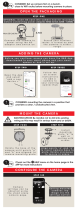
Setup the Camera
Step 1: Assemble the camera’s stand
a. Hold the metal screw up.
b. Face the back of the camera to the stand and turn the camera clockwise to
attach it to the stand.
Note:At this time, please don’t connect the power adapter.
Step 2: Connect to Iris™
Adding your Iris™ camera to an existing Iris™ system:
1. Set-up your camera as described in the steps above.
2. Log into your Iris™ dashboard at lowes.com/iris and click the devices link.
3. Select add devices.
4. Follow the on screen instructions. The Iris™ system will find your camera
and add it to your system.
Adding your Iris™ camera to a new Iris™ system:
1. Set-up your camera as described in the steps above.
2. Follow the installation process described in your Iris™ quick start guide.
3. The onscreen instructions will describe the steps to add your camera. The
Iris™ system will find your camera and add it to your system.
RC8221 Iris
™
Camera

5
RC8221 Iris
™
Camera
MountingtheCamera(Optional)
Note:The camera can also be placed on a table using the stand provided.
Note:Please ensure the camera is configured and added to the network
before permanent mounting.
Wall Mounting
Step 1: Install mount screws
a. Mark two points at the same height from the ground, where you would like
to mount your camera.
b. Screw in 2/3 of the length of the mounting screws into the wall.
Step 2: Mount the camera
a. Hook the mounting holes located at the bottom of the camera’s stand into
the mounting screws.
Step 3: Complete the camera’s mount
a. Make sure the camera is firmly fixed on the wall.
b. Adjust the camera to the preferred position.

6
RC8221 Iris
™
Camera
Ceiling Mounting
Step 1: Disassemble the iron plate
a. Screw the swivel connector off the stand. Then use the screwdriver to
remove the screw of the stand base.
b. Disassemble the iron plate from the bottom of the stand.
Step 2: Install mount screws
a. Place the iron plate in the desired position of the ceiling. Screw the
mounting screws into ceiling through the 2 round holes of the iron plate.
Step 3: Mount the camera
a. Use the screwdriver to tighten the screw of the stand base.
b. Attach the swivel connector to the base by turning clockwise.

7
RC8221 Iris
™
Camera
Step4:Completethecamera’smount
a. Make sure the camera is firmly fixed on the ceiling.
b. Adjust the camera to the preferred position.
c. Attach the camera to the swivel connector by turning it clockwise.

8
RC8221 Iris
™
Camera
Appendix A
Specications
Camera
Model Network Camera
Dimensions 63 mm (W) x 95 mm (H) x 35 mm (D)
Operating Temperature 0° C to 50° C
Video compression H.264, MPEG4 and MJPEG
Image resolution 1280 x 720, 640 x 480 (VGA, system default ),
320 x 240 (QVGA), 160 x 120 (QQVGA)
Storage Temperature -20° C to 70° C
NetworkProtocols TCP/IP, HTTP, HTTPS, DHCP, NTP, SMTP,
UPnP, FTP, RTP/RTSP
NetworkInterface 1 Ethernet 10/100BaseT (RJ45) LAN
connection
Wireless interface IEEE 802.11n /8 02.11b/802.11g c omp atib le,
Infrastructure/Ad-hoc mode, WEP 64/128 bit,
WPA/WPA2 personal security support
LEDs 3
Micro-SD Card slot 1
Power Adapter 12V/1A, 100~240 VAC
Regulatory Approvals
FCC Statement
This equipment generates, uses, and can radiate radio frequency energy
and, if not installed and used in accordance with the instructions, may cause
harmful interference to radio communications. However, there is no guarantee
that interference will not occur in a particular installation. If this equipment
does cause harmful interference to radio or television reception, which can be
determined by turning the equipment off and on, the user is encouraged to try to
correct the interference by one of the following measures:
• Reorientorrelocatethereceivingantenna.
• Increasetheseparationbetweentheequipmentandreceiver.
• Connecttheequipmentintoanoutletonacircuitdifferentfromthatto
which the receiver is connected.
• Consultthedealeroranexperiencedradio/TVtechnicianforhelp.
To assure continued compliance, any changes or modifications not expressly
approved by the party responsible for compliance could void the user’s authority
to operate this equipment. (Example - use only shielded interface cables when
connecting to computer or peripheral devices).

9
RC8221 Iris
™
Camera
FCC Radiation Exposure Statement
This equipment complies with FCC RF radiation exposure limits set forth for an
uncontrolled environment. This equipment should be installed and operated with
a minimum distance of 20 centimeters between the radiator and your body.
This device complies with Part 15 of the FCC Rules. Operation is subject to the
following two conditions:
(1)Thisdevicemaynotcauseharmfulinterference,and
(2)Thisdevicemustacceptanyinterferencereceived,including
interference that may cause undesired operation.
This transmitter must not be co-located or operating in conjunction with any
other antenna or transmitter.
CE Approvals
The camera and the Ethernet camera meet the guidelines of the European
Union and comply with the 99/5/EEC and RTTE 99/5EG directives, including the
following standards:
• EN60950
• EN300328
• EN301489-1
• EN301489-17
This is a Class B product. In a domestic environment this product may cause
radio interference in which case the user may be required to take adequate
measures.
This product is UL and cUL certified and comply with UL60950-1 Information
Technology Equipment applicable requirement.

P/N: Versión de documento: 1.0, Copyright 2012. Todos los derechos reservados. Todos los nombres y las marcas comerciales son propiedad de sus respectivos propietarios.
P/N: Document Version: 1.0, Copyright 2012. All Rights Reserved. All trademarks and trade names are the properties of their respective owners
/