Takagi 100123330 Owner's manual
- Category
- Water heaters & boilers
- Type
- Owner's manual
This manual is also suitable for

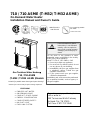
Gas Tankless Water Heater
710 / 710 ASME
(T-M32 / T-M32 ASME )Models
Suitableforpotablewaterheatingan dspace‐heating
*
*Pleaserefertolocalcodesforspace‐heatingcompliance.
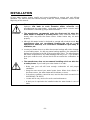
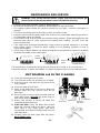
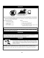
-Do not store or use gasoline or other
flammable vapors and liquids in the vicinity
of this or any other appliance.
-WHAT TO DO IF YOU SMELL GAS
Do not try to light any appliance.
Do not touch any electric switch, do not
use any phone in your building.
Immediately call your gas supplier from
a neighbor's phone. Follow the gas
supplier's instructions.
If you cannot reach your gas supplier,
call the fire department.
-Installation and service must be performed
by a qualified installer, service agency or
the gas supplier.
710 / 710 ASME (T-M32/ T-M32 ASME)
On-Demand Water Heater
Installation Manual and Owner’s Guide
FEATURING
ENDLESS HOT WATER
ON-DEMAND USAGE
COMPACT, SPACE SAVING
ENERGY CONSERVATION
COMPUTERIZED SAFETY
NO PILOT LIGHT
EASY-LINK SYSTEM
If you have any questions, please
call or write to:
500 Tennessee Waltz Parkway
Ashland City, TN 37015
Toll Free: 1-877-737-2840
ANSIZ21.10.3
andCSA4.3
If the information in these
instructions is not followed
exactly, a fire or explosion
may result causing property
damage, personal injury or
death.
WARNING
For supplying potable
hot water
ASME model ONLY
HLW

- 2 -
CONTENTS
NOTE
*All references to the 710 (T-M32) also refer to the
710 ASME (T-M32 ASME) model.
*Check the rating plate to ensure this product
matches your specifications.
*In accordance with ANSI Z21.10.3,
CO emission does not exceed 400 PPM for
normal input.
SPECIFICATIONS
Natural Gas Input
(Operating Range)
Min: 24,000 Btu/h
Max: 240,000 Btu/h
Propane Input
(Operating Range)
Min: 24,000 Btu/h
Max: 240,000 Btu/h
Gas Connection 3/4” NPT
Water Connections
3/4” NPT
Water Pressure
15 - 150 psi *
Natural Gas
Inlet Pressure
Min. 5.0” WC
Max. 10.5” WC
Propane
Inlet Pressure
Min. 8.0” WC
Max. 14.0” WC
Manifold Pressure**
Natural: 2.35” WC
Propane: 3.55” WC
Weight
59 lbs.
Dimensions
H23.6”×W18.5”×D8.9”
Ignition
Electric Ignition
Electric
Supply
120 VAC / 60 Hz
Consumption
Operation
112 W
(0.93 A)
Standby
8.9 W
(0.07 A)
Freeze-
Protection
187 W
(1.56 A)
SPECIFICATIONS……………………….
INTRODUCTION…………………………
SAFETY GUIDELINES………………....
INSTALLATION…………………………..
General…………………………………
Included Accessories….……………….
Warning for Installations………………
Outdoor Installation…………………...
Indoor Installation…………………...…
Direct Intake Vent System…………….
Venting Instructions………………......
Gas Supply / Gas Pipe Sizing………..
Water Connections……………………
Pressure Relief Valve…………………
Electrical Connections……………......
Remote Controller Connections………
Pump Control Connections……………
Pump Control Mode……………………
Easy-Link System ……………………..
Multi-Unit System………………………
Initial Operation………………………..
NORMAL OPERATION………………….
Normal Operation…………………......
Flow……………………………………..
Freeze Protection System…………...
Temperature Settings………………….
Maintenance and Service………..…….
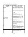
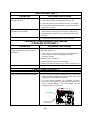
GENERAL TROUBLESHOOTING……..
OPERATING SAFETY……..……………..
APPLICATIONS………………………......
Re-Circulation…………………………..
Dual-Purpose Heating……………......
ADDITIONAL CLEARANCES……………
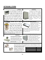
OPTIONAL ITEMS………...……………..
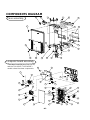
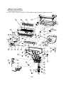
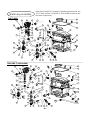
COMPONENTS DIAGRAM…………….
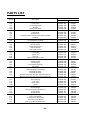
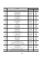
PARTS LIST………………………………
OUTPUT TEMPERATURE CHART……
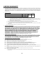
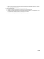
LIMITED WARRANTY……………………
2
3
4
5
6
6
7
8
9
10
11
15
18
18
19
20
21
22
24
28
30
31
31
33
33
34
35
36
39
41
41
42
43
44
45
48
50
51
The manufacturer reserves the right to discontinue, or change at any time,
specifications or designs without notice and without incurring obligations.
*40 psi or above is recommended for maximum flow.
**The Manifold Pressure is the factory setting and
generally should not need adjustment.

- 3 -
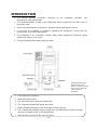
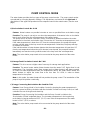
INTRODUCTION
1. A hot water tap is turned on.
2. Water enters the heater.
3. The water flow sensor detects the water flow.
4. The computer automatically ignites the burner.
5. Water circulates through the heat exchanger and then gets hot.
6. The computer will modulate the gas supply valve and water flow to produce the right
amount of hot water at the correct temperature.
7. When the tap is turned off, the unit shuts down.
*This diagram illustrates
tankless water heater
design concepts only and is
not accurate to the water
heater’s physical
description.
This manual provides information necessary for the installation, operation, and
maintenance of the water heater.
The model description is listed on the rating plate which is attached to the front cover of
the water heater.
Please read all installation instructions completely before installing this product.
If you have any problems or questions regarding this equipment, consult with the
manufacturer or its local re
p
resentative.
This equipment is an on-demand, tankless water heater designed to efficiently supply
endless hot water for
y
our needs.
The principle behind the water heater is simple:

- 4 -
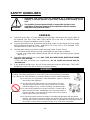
SAFETY GUIDELINES
Installation and service must be performed by a qualified installer (for
example, a licensed plumber or gas fitter), otherwise the warranty will be
void.
The installer (licensed professional) is responsible for the correct
installation of the water heater and for compliance with all national,
state/provincial, and local codes.
PLEASE READ THIS MANUAL CAREFULLY AND FOLLOW ALL DIRECTIONS.
GENERAL
1. Follow all local codes, or in the absence of local codes, follow the most recent edition of
the National Fuel Gas Code: ANSI Z223.1/NFPA 54 in the USA or CAN/CSA B149.1
Natural Gas, Propane Installation Code in Canada.
2. Properly ground the unit in accordance with all local codes or in the absence of local codes,
with the National Electrical Codes: ANSI/NFPA 70 in the USA or CSA standard C22.1
Canada Electrical Code Part 1 in Canada.
3. Carefully plan where you intend to install the water heater. Please ensure:
Your water heater will have enough combustible air and proper ventilation.
Locate your heater where water leakage will not damage surrounding areas (please
refer to p. 5).
4. Check the rating plate for the correct GAS TYPE, GAS PRESSURE, WATER PRESSURE
and ELECTRIC RATING.
*If this unit does not match your requirements, do not install and consult with the
manufacturer.
5. If any problem should occur, turn off all hot water taps and turn off the gas. Then call a
trained technician or the Gas Company or the manufacturer.
WARNING
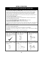
Water temperatures over 125ºF (52ºC) can cause severe burns instantly or death from
scalding. The water temperature is set at 120ºF (49ºC) from the factory to minimize
any scalding risk. Before bathing or showering always check the water temperature.
Do not store or use gasoline or other flammables, vapors, or liquids in
the vicinity of this appliance.
Do not reverse the water and/or gas connections as this will
damage the gas valves and can cause severe injury or death.
Follow the diagram on p. 17 when installing your water heater:
Do not use this appliance if any part has been in contact with or
been immersed in water. Immediately call a licensed plumber, a
licensed gas fitter, or a professional service technician to inspect
and/or service the unit if necessary.
Do not disconnect the electrical supply if the ambient temperature will drop below
freezing. The Freeze Prevention System only works if the unit has electrical power. The
warranty will not be covered if the heat exchanger is damaged due to freezing. Refer to
the section on the Freeze Prevention System on p. 33 for more information.
WARNING
Prohibited

- 5 -
INSTALLATION
All gas water heaters require careful and correct installation to ensure safe and efficient
operation. This manual must be followed exactly. Read the “Safety Guidelines” section at the
beginning of this manual.
The warranty will not cover damage caused by water quality. Water
hardness that leads to scale formation and/or corrosion may
affect/damage the water heater. Hard water scaling and/or corrosion must
be avoided or controlled by proper water treatment.
The manufacturer recommends using the direct-vent kit, when the
water heater is installed in a beauty salon. Some chemicals used in a
beauty salon may affect the flame sensor. Water heater may not work
properly.
Although this water heater is designed to operate with minimal sound, the
manufacturer does not recommend installing the unit on a wall
adjacent to a bedroom, or a room that is intended for quiet study or
meditation, etc.
Locate your heater close to a drain where water leakage will not do damage
to surrounding areas. As with any water heating appliance, the potential for
leakage at some time in the life of the product does exist. The manufacturer
will not be responsible for any water damage that may occur. If you install a
drain pan under the unit, ensure that it will not restrict the combustion air
flow.
The manufacturer does not recommend installing unit in an attic due
to safety issues. If you install your water heater in an attic:
Make sure your unit will have enough combustion air and proper
ventilation.
Keep the area around your water heater clean. When dust collects on
the flame sensor, the water heater will shut down on errors.
If the above conditions cannot be met, use the direct-vent conversion kit
9007668005 (TM-DV32).
Locate unit for easy access for service and maintenance.
A drain pan is required to be installed under the water heater in case of
leaks.
WARNING
CAUTION

- 6 -
GENERAL
1. The manifold gas pressure is preset at the factory. It is computer controlled and should
not need adjustment.
2. Maintain proper space for servicing. Install the unit so that it can be connected or
removed easily. Refer to p. 8 and p. 9 for proper clearances.
3. The electrical connection requires a means of disconnection, to terminate power to the
water heater for servicing and safety purposes.
4. If you will be installing the unit in a contaminated area with a high level of dust, sand,
flour, aerosols or other contaminants/chemicals, they can become airborne and enter
and build up within the fan and burner causing damage to the unit. In those
environments (e.g. residential or commercial laundry facilities, hair salons, pet salons,
chemical plants etc.), please purchase the optional direct-vent conversion kit and
convert the water heater to a sealed combustion unit. Direct venting allows the water
heater to draw fresh intake air from the outside. The warranty will not cover damage
caused to the unit due to installation in a contaminated environment that has not been
converted using the direct-vent conversion kit.
5. Particles from flour, aerosols, and other contaminants may clog the air vent or reduce
the functions of the rotating fan and cause improper burning of the gas. Regularly ensure
that the area around the unit is dust- or debris-free; regular maintenance is
recommended for these types of environment.
6. Do not install the unit where the exhaust vent is pointing into any opening in a building or
where the noise may disturb your neighbors. Make sure the vent termination meets the
required distance by local code from any doorway or opening to prevent exhaust from
entering a building (refer to p. 14).
INCLUDED ACCESSORIES
Check that these items below are included with the water heater.
Items
Manual
Communication Cable
Qt
y
: 1
Qty: 1

- 7 -
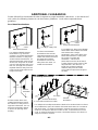
WARNING FOR INSTALLATIONS
FOR YOUR SAFETY, READ BEFORE INSTALLATION:
Do not install the heater where water, debris
or flammable vapors may get into the flue
terminal. This may cause damage to the
heater and void the warranty.
Do not have the vent terminal pointing toward
any opening into a building. Do not locate
your heater in a pit or location where gas and
water can accumulate.
Do not install this water heater under an
overhang less than 3 feet from its top or
eaves. The area under an overhang must be
open to three sides.
Do not install the water heater vent terminator
within 1 ft. in the USA of any air intake or
building opening, and within 3 ft. in Canada of
any air intake or building opening. (Refer to
p.14)
Do not install next to a dryer or any source of
airborne debris that can be trapped inside the
combustion chamber, unless the system is
direct vented.
Prohibited Prohibited
3 Ft.

- 8 -
The dark square is the direction
the dipswitch should be set to.
1
2
3
4
5
6
7
8
TMP1
TMP2
TMP3
MODE
DIRE
OUT
D-PRT
MST
ON
Keep the clearances.
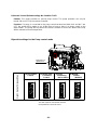
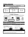
OUTDOOR INSTALLATION
1. Follow all local codes, or in the absence of local codes, follow the most recent edition of
the National Fuel Gas Code: ANSI Z223.1/NFPA 54 in the USA or CAN/CSA B149.1
Natural Gas, Propane Installation Code in Canada.
2. Install outdoors only in areas with mild, temperate climates.
3. Ensure that the unit is set for outdoor installation. Locate the left bank of dipswitches to
the bottom of the 7-Seg. LED on the computer board. The ‘OUT’ dipswitch on that
bank should be switched to its ‘ON’ (right) position (Do not adjust the right bank of
dipswitches).
4. The outdoor vent cap must be used when unit is installed outdoor. The manufacturer
requires the use of its part No. 9007676005 (TM-VC32).
5. When installed outdoors, the water heater shall be wall-mounted or mounted on a stand.
Locate the water heater in an open, unroofed area and maintain the following minimum
clearances:
Make sure power to the unit is
turned OFF before changing
the dipswitch settings.
Left Bank of Dipswitches
7-Seg LED
Left bank of
dipswitches
Right bank of
dipswitches
There is a 2” clearance from the
left and right sides of the unit to
combustible and non-combustible
surfaces. However, if any portion
or area of the surface is exposed
to the exhaust fumes (i.e. directly
to the sides of the vent cap), that
surface must be at least 24”
away.
Bottom 12”
*Front 24”
Front 4”
(24” Recommended
for Maintenance)
Back 1”
Side 2”
Side 2”
Top 36”
*Side 24”
*Side 24”

- 9 -
Keep the following
clearances.
INDOOR INSTALLATION
1. Follow all local codes, or in the absence of local
codes, follow the most recent edition of the
National Fuel Gas Code: ANSI Z223.1/NFPA 54
in the USA or CAN/CSA B149.1 Natural Gas,
Propane Installation Code in Canada.
2. When installed indoors, the water heater shall be
located in an area to maintain the following
minimum clearances around the unit:
Combustion Air Supply
The water heater location must provide enough air for proper combustion and ventilation of the
surrounding area. See the latest edition of ANSI Standard Z223.1 or any applicable local codes.
In general, these requirements specify that if the unit is installed in a confined space, there must
be a permanent air supply opening.
Minimum recommended air supply opening size for water heater:
Water heater size
When drawing
make-up air from
outside the building
When drawing make-up
air from inside
the building (from other rooms within)
MAX
240,000 BTU
/h
16.0 Sq. IN
240 Sq. IN
When combustion air is supplied
from outside the building, an
opening communicating directly
with the outside should have a
minimum free area of one
square inch per 15,000 BTUH
input of the total input rating of
water heater in the enclosed
area.
When combustion air is supplied from
inside the building, an opening
communicating with the rest of the
dwelling should have a minimum free
area of one square inch per 1,000
BTUH input of the total input rating of
water heater in the enclosed area.
This opening should never be less
than 199 sq. in.
Combustible Air Supplied by Mechanical fan or Make up air device
The water heater is equipped with a combustible air sensor that will shut off the unit when
inadequate combustible air supply to unit is detected.
If a mechanical fan or make up air device is used to supply air to the water heater or
utility room, the installer should make sure it does not create drafts which could cause
nuisance shutdowns.
If a blower is necessary to provide adequate combustion air to the water heater, the
blower and water heater must be set up so that the water heater cannot fire unless the
blower is operating. Possible methods include the use of external flow
sensors/transmitters and relays.
Top 12”
Side 2”
Side 2”
Front 4”
(24” Recommended
for Maintenance)
Bottom 12”
Back 1”

- 10 -
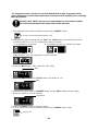
The dark square is the direction
the dipswitch should be set to.
EXHAUST
INLET
1
2
3
4
5
6
7
8
TMP1
TMP2
TMP3
MODE
DIRE
OUT
D-PRT
MST
ON
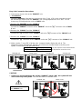
DIRECT INTAKE VENT SYSTEM
This water heater may be converted to a direct-vent (sealed combustion) appliance by installing
an adapter (Part No. 9007668005 (TM-DV32)) which will bring all required combustible air from
outside the building. When installing the direct-vent conversion kit, please follow all instructions
included with the kit.
The water heater must be installed in a location where the proper amount of combustible
air will be available to it at all times without obstructions.
If used as a direct-vent appliance, the water heater requires a 4” combustible air supply
pipe. The intake pipe must be sealed airtight.
Air supply pipe can be made of ABS, PVC, galvanized steel, corrugated aluminum,
corrugated stainless steel or Category III stainless steel.
Change the dipswitch settings to the direct-vent system. (See diagram below)
Sidewall venting is recommended for the direct-vent system.
The manufacturer recommends running the exhaust vent and the intake pipe parallel.
The Direct-Vent Conversion Kit has an “INLET” mark as shown below. Do not
reverse the INLET and the EXHAUST connections when installing vent pipes.
Direct-Vent
Conversion Kit
Make sure power to the unit is
turned OFF before changing
the dipswitch settings.
Left Bank of Dipswitches
DIRECT-VENT
CONVERSION KIT
“INLET” mark
7-Seg LED
Left bank of
dipswitches
Right bank of
dipswitches

- 11 -
VENTING INSTRUCTIONS
WARNING: Improper venting of this appliance can result in excessive levels of
carbon monoxide which can result in severe personal injury or death.
This water heater must be vented in accordance with the section “Venting of Equipment" of the
latest edition of the Natural Fuel Gas Code: ANSI Z223.1, all applicable local building codes,
and Section 7 of CAN/CSA B149.1 Natural Gas in Canada, Propane Installation Code in
Canada.
EXHAUST VENT
This is a Category III appliance and must be vented accordingly. The vent system must be
sealed airtight. All seams and joints without gaskets must be sealed with high heat resistant
silicone sealant or UL listed aluminum adhesive tape having a minimum temperature rating of
350 ºF. For best results, a vent system should be as short and straight as possible.
1. This water heater is a Category III appliance and must be vented accordingly with any 4”
vent approved for use with Category III or Special BH type gas vent.
2. The manufacturer recommends the NovaVent line. However, the following are also UL
listed manufacturers: ProTech Systems Inc. (FasNSeal), Metal-Fab Inc., and Heat-Fab Inc.
(Saf-T Vent).
3. Follow the vent pipe manufacturer’s instructions when installing the vent pipe.
4. Do not common vent this appliance with any other vented appliance. (Do not
terminate vent into a chimney. If the vent must go through the chimney, the vent must run
all the way through the chimney with Category III approved or Special BH vent pipe.)
5. The maximum length of exhaust vent piping must not exceed 50 ft. deducting 5 ft. for each
elbow used in the venting system. Do not use more than 5 elbows.
Diameter Max. No. of Elbows Max. Vertical or Horizontal Length
4” 5 Ea. 50 ft
*For each elbow added, deduct 5 ft. from max. vent length.
No. of Elbows Max. Vertical or Horizontal Length
0 50 ft.
1 45 ft.
2 40 ft.
5 25 ft.
6. When the horizontal vent run exceeds 5 ft., support the vent run at 3 ft. intervals with
overhead hangars.
7. The manufacturer will not be responsible for any damage to the water heater caused by
condensation from the vent. Installing a condensate drain is recommended. Please refer
to p. 13 for the diagrams.
When installing the vent system, all applicable national and local codes must be
followed. If you install thimbles, fire stops or other protective devices and they
penetrate any combustible or noncombustible construction, be sure to follow all
applicable national and local codes.

- 12 -
VENT TERMINATION
WARNING: Improper installation can cause nausea or asphyxiation, severe injury
or death from carbon monoxide and flue gases poisoning. Improper installation
will void product warranty.
The vent termination provides a means of installing vent pipe through the building wall and
must be located in accordance with ANSI Z223.1/NFPA 54, or in Canada with CAN/CSA-
B149.1 and local applicable codes.
A proper sidewall vent termination is recommended when the water heater is vented through
a sidewall. If the water heater is converted to a direct-vent unit, a proper sidewall direct-vent
termination is to be used.
General rules for venting the water heater are:
1. Place the water heater as close as possible to the vent termination.
2. The vent collar of the water heater must be fastened directly to an unobstructed vent pipe.
3. Do not weld the vent pipe to the water heater collar.
4. Do not cut the vent collar of the unit.
5. The weight of the vent stack must not rest on the water heater.
6. The vent must be easily removable from the top of the water heater for normal service and
inspection of the unit.
7. The water heater vent must not be connected to any other gas appliance or vent stack.
8. Avoid locating the water heater vent termination near any air intake devices. These fans
can pick up the exhaust flue products from the water heater and return them to the building.
This can create a health hazard.
9. Avoid using an oversized vent pipe or using extremely long runs of the pipe.
10. Locate the vent termination so that it cannot be blocked by any debris, at any time. Most
codes require that the termination be at least 12 inches above grade, but the installer may
determine if it should be higher depending on the job site condition and applicable codes.
11. For rooftop venting, a rain cap must be installed.
12. The manufacturer recommends the NovaVent line. However, the following are also UL
listed manufacturers: ProTech Systems Inc. (FasNSeal), Metal-Fab Inc., and Heat-Fab Inc.
(Saf-TVent).

- 13 -
Horizontal Installation Diagram
Vertical Installation Diagram
Regarding the clearance from the terminal to the air inlet or opening, refer to the next page.
Install a condensation drain in the venting.
Follow the vent manufacturer’s instructions and local codes.
Do not common vent or connect any vent from other appliances to the water heater vent.
Use 4” category III approved or Special BH, single or double wall stainless steel vent pipe.
Wall
Roof
Rain cap
Roof flashing
Sidewall vent
termination
Vertical condensation drain
(Install according to local codes)
Backflow preventer
(Recommended for freezing
weather conditions: 36 °F and
below)
Backflow preventer
(Recommended for freezing
weather conditions: 36 °F and
below)
Vertical condensation drain
(Install according to local codes)

- 14 -
VENT CLEARANCES
Canada U.S.A
Direct vent and
other than Direct
Vent
Direct vent Other than Direct Vent
A
Clearance above grade, veranda, porch,
deck, or balcony.
1 foot 1 foot 1 foot
B
Clearance to window or door that may be
opened.
3 feet 1 foot
4 feet from below or
side opening. 1 foot
from above opening.
C
Clearance to permanently closed window * * *
D
Vertical clearance to ventilated soffit
located above the vent terminator within a
horizontal distance of 2 feet (61cm) from
the center line of the terminator.
* * *
E
Clearance to unventilated soffit * * *
F
Clearance to outside corner * * *
G
Clearance to inside corner * * *
H
Clearance to each side of center line
extended above meter/regulator assembly
3 feet * *
I
Clearance to service regulator vent outlet. 3 feet * *
J
Clearance to non-mechanical air supply
inlet to building or the combustion air inlet
to any other application.
3 feet 1 foot
4 feet from below or
side opening. 1 foot
from above opening.
K
Clearance to mechanical air supply inlet. 6 feet 3 feet 3 feet
L
Clearance above paved sidewalk or
paved driveway located on public
property.
7 feet * 7 feet
M
Clearance under veranda, porch deck, or
balcony.
1 foot * *
*For clearances not specified in ANSI Z223.1 / NFPA 54 or CAN/CSA-B149.1, please use clearances in
accordance with local installation codes and the requirement of the gas supplier.

- 15 -
Size the gas pipe appropriately to supply the necessary volume of gas required for the
water heater using ANSI Z223.1/NFPA 54 in the USA or CAN/CSA B149.1 in Canada
or local codes. Otherwise, flow capabilities and output temperatures will be limited.
GAS SUPPLY AND GAS PIPE SIZING
1. Turn off all electric power to the water heater if service is to be performed.
2. Turn the manual gas valve located on the outside of the unit clockwise to the off position.
WARNING: Conversion of this unit from natural gas to propane or vice versa will
void all warranty. Contact your local distributor to get the correct unit for your gas
type. The manufacturer is not liable for any property and/or personal
damage resulting from gas conversions.
*Check that the type of gas matches the rating plate first.
The minimum and maximum inlet gas pressures are:
Gas type Inlet gas pressure
Natural Gas Min. 5.0” W.C. – Max. 10.5” W.C.
Propane Min. 8.0” W.C. – Max. 14.0” W.C.
Inlet gas pressures that fall outside the range of values listed above may adversely affect the
performance of the water heater. These pressures are measured when the water heater is in full
operation.
Inlet gas pressure must not exceed the above maximum values; gas pressure above the specified
range will cause dangerous operating conditions and damage to the unit. Ensure that any and all
gas regulators used are operating properly and are providing gas pressures within the specified
range shown above.
Until testing of the main gas line supply pressure is completed, ensure the gas line to the water
heater is disconnected to avoid any damage to the water heater.
-Gas connections-
1. Install a manual gas shutoff valve between the water heater and the gas supply line.
2. When the gas connections are completed, it is necessary to perform a gas leak test either by
applying soapy water to all gas fittings and observing for bubbles or by using a gas leak detection
device.
The water heater and its individual shutoff valve must be disconnected from the gas supply
piping system during any pressure testing of that system at test pressures in excess of 1/2 psi
(3.5 kPa).
The water heater must be isolated from the gas supply piping system by closing its individual
manual shutoff valve during any pressure testing of the gas supply piping system at test
pressures equal to or less than 1/2 psi (3.5kPa).
3. Always purge the gas line of any debris and/or water before connecting to the gas inlet.
TO TURN OFF GAS TO APPLIANCE
NOTICE

- 16 -
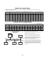
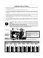
Natural Gas Supply Piping
Maximum Delivery Capacity of Cubic Feet of Gas per Hour of IPS Pipe Carrying Natural Gas of 0.60 Specific Gravity
Based on Pressure Drop of 0.5” WC
Based on Energy Content of 1,000 BTU/Cubic Ft.: 710 (T-M32) requires 240 Cubic Ft./hr. Unit: Cubic Feet per Hour
Pipe Size Length
Diameter 10' 20' 30' 40' 50' 60' 70' 80' 90' 100' 125' 150' 200'
¾”
363 249 200 171 152 138 127 118 111 104 93 84 72
1”
684 470 377 323 286 259 239 222 208 197 174 158 135
1 ¼”
1,404 965 775 663 588 532 490 456 428 404 358 324 278
1 ½”
2,103 1,445 1,161 993 880 798 734 683 641 605 536 486 416
2”
4,050 2,784 2,235 1,913 1,696 1,536 1,413 1,315 1,234 1,165 1,033 936 801
2 ½”
6,455 4,437 3,563 3,049 2,703 2,449 2,253 2,096 1,966 1,857 1,646 1,492 1,277
3”
11,412 7,843 6,299 5,391 4,778 4,329 3,983 3,705 3,476 3,284 2,910 2,637 2,257
Propane (LP) Gas Supply Piping
Maximum Capacity of Propane (LP) Gas Based on 11” WC supply pressure at a 1.0” WC pressure drop
Unit: kBTU per Hour
Pipe Size
Length
Diameter 10’ 20’ 30’ 40’ 50’ 60’ 70’ 80’ 90’ 100’ 125’ 150’ 200’
¾”
567 393 315 267 237 217 196 185 173 162 146 132 112
1”
1,071 732 590 504 448 409 378 346 322 307 275 252 213
1 ¼”
2,205 1,496 1,212 1,039 913 834 771 724 677 630 567 511 440
1 ½”
3,307 2,299 1,858 1,559 1,417 1,275 1,181 1,086 1,023 976 866 787 675
2”
6,221 4,331 3,465 2,992 2,646 2,394 2,205 2,047 1,921 1,811 1,606 1,496 1,260
10’ Length
3/4” Pipe Size
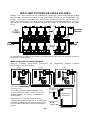
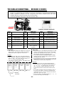
Gas Sizing Example
(Natural Gas)
15’ Length
1/2” Pipe Size
10’ Length
1/2” Pipe Size
Furnace
120,000BTU
10’ Length
1” Pipe Size
Water
Heater
240,000BTU
5’ Length
1-1/4” Pipe Size
Range
65,000BTU
10’ Length
3/4” Pipe Size
Dryer
35,000BTU
15’ Length
3/4” Pipe Size
5’ Length
1-1/4” Pipe Size
Gas Meter
B
A
Based on Energy Content of 1,000BTU/Cubic Ft:
Divide each appliance’s BTU requirement by 1,000BTU to get
the appliances Cubic Ft. requirement.
Take into account the distance the appliance is from the gas
meter, look in the above gas chart to properly size the line.
For sections of the gas line supplying gas to more than one
appliance (Ex: Point A to Point B), add up the cubic ft.
requirements of the appliances that are being supplied by that
section, and size to the farthest appliance.
For Example: The section from A to B supplies gas to the
furnace, range, and dryer. Adding up the BTU requirements and
dividing by 1,000 yields a cubic ft. requirement of 220 cubic ft. of
gas. The farthest appliance is the range, which is 50 ft. away
from the meter. Looking at the above chart, and under the
column of 50ft., Section A to B needs to be 1” in order to supply
220 cubic ft.

- 17 -
1. Turn off all electric power to the water heater if service is to be performed.
2. Turn the manual gas valve located on the outside of the unit clockwise to
the off position.
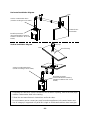
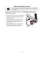
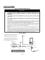
-Measuring inlet gas pressure-
The water heater cannot perform properly without sufficient inlet gas pressure. Below are
instructions on how to check the inlet gas pressure. THIS IS ONLY TO BE DONE BY A
LICENSED PROFESSIONAL.
1. Shut off the manual gas valve on the supply gas line.
2. Remove the screw for the pressure port located
on the gas inlet of the water heater shown in the
diagram to the right.
3. Connect the manometer to the pressure port.
4. Re-open the manual gas valve. Check to see that
there are no gas leaks. Open some of the
fixtures that use the highest flow rate to turn on
the water heater.
5. Check the inlet gas pressure. When the water
heater is on maximum burn, the manometer
should read from 5.0” to 10.5” WC for Natural
gas, from 8.0” to 14.0” WC for Propane.

- 18 -
WATER CONNECTIONS
・Do not use this water heater if any part has been submersed under water. Immediately call a
licensed professional to inspect the water heater and to replace any damaged parts.
・Do not reverse the hot outlet and cold inlet connections to the water heater. This will not
activate the water heater.
All pipes, pipe fittings, valves and other components, including soldering materials, must be
suitable for potable water systems.
1. All pipes, pipe fittings, valves and other
components, including soldering materials, must
be suitable for potable water systems.
2. A manual shut off valve must be installed on the
cold water inlet to the water heater between the
main water supply line and the water heater.
3. In addition, a manual shut off valve is also
recommended on the hot water outlet of the unit.
If the water heater is installed within, or subjected
to, a closed loop water system, a thermal
expansion tank must be installed.
4. Before installing the water heater, flush the water
line to remove all debris, and after installation is
complete, purge the air from the line. Failure to
do so may cause damage to the heater.
5. There is a wire mesh filter within the cold inlet to trap debris from entering your heater.
This will need to be cleaned periodically to maintain optimum flow.
PRESSURE RELIEF VALVE
The water heater has a high-temperature shut off switch built in as a standard safety feature
(called a Hi-Limit switch) therefore a “pressure only” relief valve is required.
This unit does not come with an approved pressure relief valve.
An approved pressure relief valve must be installed on the hot water outlet.
The pressure relief valve must conform to ANSI Z21.22 or CAN 1-4.4 and installation must
follow local code.
The discharge capacity must be at least 240,000 BTU/h.
The pressure relief valve needs to be rated for a maximum of 150 psi.
The discharge piping for the pressure relief valve must be directed so that the hot water
cannot splash on anyone or on nearby equipment.
Attach the discharge tube to the pressure relief valve and run the end of the tube to within
6" from the floor. This discharge tube must allow free and complete drainage without any
restrictions.
If the pressure relief valve installed on the water heater discharges periodically, this may
be due to a defective thermal expansion tank or defective pressure relief valve.
The pressure relief valve must be manually operated periodically to check for correct
operation.
No valve must be placed between the relief valve and the water heater.
For the ASME model, the pressure relief valve must conform to and be installed in
accordance with ASME code.
FOR YOUR SAFETY, READ BEFORE OPERATING:
Pressure Relief Valve
As Close as
Possible
Cold inlet
Hot outlet
Gas

- 19 -
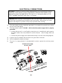
ELECTRICAL CONNECTIONS
WARNING: Follow the electrical code requirements of the local authority having
jurisdiction. In the absence of such requirements, follow the latest edition of the
National Electrical Code ANSI/NFPA 70 in the U.S. or the latest edition of CSA
C22.1 Canadian Electrical Code, Part 1, in Canada.
CAUTION: When servicing or replacing parts within the water heater, label all wires prior to
disconnection to facilitate an easy and error free reconnection. Wiring errors can cause
improper and dangerous operation. Verify proper operation after servicing.
1. The water heater must be electrically grounded. Do not attach the ground wire to either
the gas or the water piping.
2. The water heater requires 120 VAC / 60 Hz electrical power supply that is properly
grounded.
A proper disconnect (i.e. on/off switch, power plug, etc.) controlling the main power to
the water heater must be provided for service reasons. (Must comply with local
codes).
Connect the power supply to the water heater exactly as shown in the wiring diagram;
3. A green screw is provided in the junction box to ground the connection.
4. Can be hardwired or wired to a plug-in.
5. The use of a surge protector is recommended in order to protect the unit from power
surges.
Ground
Connect Power supply
120 VAC / 60Hz

- 20 -
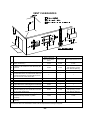
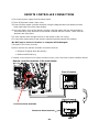
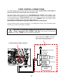
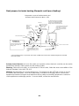
REMOTE CONTROLLER CONNECTIONS
1) Disconnect power supply from the water heater.
2) Take off the water heater’s front cover.
3) Please find the remote controller terminals using the diagram below (located around the
lower right-hand side of the water heater).
4) Open the plastic cover of the remote controller, and then attach the two fork terminals to
connector base of the backside of the remote controller with two screws. Make sure the
terminals are firmly fixed.
5) Put the remote wires through the hole on the bottom of the unit casing.
6) Connect the remote wires to the remote controller terminal properly
(No polarity).
*Do NOT jump or short-circuit wires, or computer will be damaged.
7) Replace Front Cover securely.
8) Wires used for the remote controller connection must be:
Minimum 20 gauge wire (No polarity)
Maximum 400 feet long
P
A
R
E
N
T
Back of remote
Front of remote
Connect to these terminals
Connect to these terminals
Remote controller terminals of the water heater
*For details on the connection to the remote controller accessory, refer to the remote controller Installation Manual.
Page is loading ...
Page is loading ...
Page is loading ...
Page is loading ...
Page is loading ...
Page is loading ...
Page is loading ...
Page is loading ...
Page is loading ...
Page is loading ...
Page is loading ...
Page is loading ...
Page is loading ...
Page is loading ...
Page is loading ...
Page is loading ...
Page is loading ...
Page is loading ...
Page is loading ...
Page is loading ...
Page is loading ...
Page is loading ...
Page is loading ...
Page is loading ...
Page is loading ...
Page is loading ...
Page is loading ...
Page is loading ...
Page is loading ...
Page is loading ...
Page is loading ...
Page is loading ...
-
 1
1
-
 2
2
-
 3
3
-
 4
4
-
 5
5
-
 6
6
-
 7
7
-
 8
8
-
 9
9
-
 10
10
-
 11
11
-
 12
12
-
 13
13
-
 14
14
-
 15
15
-
 16
16
-
 17
17
-
 18
18
-
 19
19
-
 20
20
-
 21
21
-
 22
22
-
 23
23
-
 24
24
-
 25
25
-
 26
26
-
 27
27
-
 28
28
-
 29
29
-
 30
30
-
 31
31
-
 32
32
-
 33
33
-
 34
34
-
 35
35
-
 36
36
-
 37
37
-
 38
38
-
 39
39
-
 40
40
-
 41
41
-
 42
42
-
 43
43
-
 44
44
-
 45
45
-
 46
46
-
 47
47
-
 48
48
-
 49
49
-
 50
50
-
 51
51
-
 52
52


Takagi 100123330 Owner's manual
- Category
- Water heaters & boilers
- Type
- Owner's manual
- This manual is also suitable for
Ask a question and I''ll find the answer in the document
Finding information in a document is now easier with AI
Related papers
-
Takagi 100123396 Owner's manual
-
Takagi T-H3-DV Installation Manual And Owner's Manual
-
Takagi Mobius T-M1 Owner's manual
-
-
-
-
Takagi GTS-140-NIH, GTS-240-NIH, GTS-340-NIH, GTS-540-NIH, GTS-140-NEH, GTS-240-NEH, GTS-340-NEH, GTS-540-NEH, GTS-140-PEH, GTS-140-PIH, , GTS-240-NIH , GTS-240-PIH , GTS-340-NIH , GTS-340-PIH , GTS-540-NIH , GTS-540-PIH , GTS-540P-NIH , GTS-540P-PIH Owner's manual
-
-
-
Other documents
-
State Water Heaters 710 Installation Manual And Owner's Manual
-
A.O. Smith ATIO-710-P Technical Documents
-
Moen HC200508 User manual
-
Dakota Alert AD-SSW User manual
-
 G.F. Garden GF80545073 Installation guide
-
-
 PowerStar AE-115 User guide
-
-
-

