Page is loading ...

2E

ii
To ensure long, trouble-free operation, please
read this manual carefully.
Precautions
Location
Using the unit in the following locations can result in a mal-
function.
• In direct sunlight
• Locations of extreme temperature or humidity
• Excessively dusty or dirty locations
• Locations of excessive vibration
Power supply
Please connect the designated AC/AC power supply to an
AC outlet of the correct voltage. Do not connect it to an AC
outlet of voltage other than that for which your unit is
intended.
The AC/AC power supply will produce a certain amount of
heat during operation, but this is not a malfunction. When
power is connected, place it in a well ventilated location,
and avoid placing it on a plastic object or where heat
buildup might occur.
Interference with other electrical devices
This product contains a microcomputer. Radios and televi-
sions placed nearby may experience reception interfer-
ence. Operate this unit at a suitable distance from radios
and televisions.
Handling
To avoid breakage, do not apply excessive force to the
switches or controls.
Care
If the exterior becomes dirty, wipe it with a clean, dry cloth.
Do not use liquid cleaners such as benzene or thinner, or
cleaning compounds or flammable polishes.
Keep this manual
After reading this manual, please keep it for later refer-
ence.
Keeping foreign matter out of your equipment
• Never set any container with liquid in it near this equip-
ment. If liquid gets into the equipment, it could cause a
breakdown, fire, or electrical shock.
• Be careful not to let metal objects get into the equip-
ment. If something does slip into the equipment,
unplug the AC/AC power supply from the wall outlet.
Then contact your nearest Korg dealer or the store
where the equipment was purchased.
THE FCC REGULATION WARNING (for U.S.A.)
This equipment has been tested and found to comply with
the limits for a Class B digital device, pursuant to Part 15 of
the FCC Rules. These limits are designed to provide rea-
sonable protection against harmful interference in a resi-
dential installation. This equipment generates, uses, and
can radiate radio frequency energy and, if not installed and
used in accordance with the instructions, may cause harm-
ful interference to radio communications. However, there is
no guarantee that interference will not occur in a particular
installation. If this equipment does cause harmful interfer-
ence to radio or television reception, which can be deter-
mined by turning the equipment off and on, the user is
encouraged to try to correct the interference by one or
more of the following measures:
• Reorient or relocate the receiving antenna.
• Increase the separation between the equipment and
receiver.
• Connect the equipment into an outlet on a circuit differ-
ent from that to which the receiver is connected.
• Consult the dealer or an experienced radio/TV techni-
cian for help.
Unauthorized changes or modification to this system can
void the user’s authority to operate this equipment.
CE mark for European Harmonized Standards
CE mark which is attached to our company’s products of
AC mains operated apparatus until December 31, 1996
means it conforms to EMC Directive (89/336/EEC) and CE
mark Directive (93/68/EEC). And, CE mark which is
attached after January 1, 1997 means it conforms to EMC
Directive (89/336/EEC), CE mark Directive (93/68/EEC)
and Low Voltage Directive (73/23/EEC).
Also, CE mark which is attached to our company’s products
of Battery operated apparatus means it conforms to EMC
Directive (89/336/EEC) and CE mark Directive (93/68/
EEC).

1
Handling of the internal
hard disk
Do not apply physical shock to this device. In partic-
ular, you must never move this device or apply
physical shock while the power is turned on. This
can cause part or all of the data on disk to be lost, or
may damage the hard disk or interior components.
When this device is moved to a location where the
temperature is radically different, water droplets
may condense on the disk drive. If the device is used
in this condition, it may malfunction, so please allow
several hours to pass before operating the device.
Do not repeatedly turn the power on/off. This may
damage not only the D12, but also any SCSI devices
that are connected.
This device begins to access the hard disk immedi-
ately after the power is turned on.
Never turn off the power while the HDD access indi-
cator is lit or blinking. Doing so can cause all or part
of the data on disk to be lost, or may cause malfunc-
tions such as hard disk damage.
If the hard disk has been damaged due to incorrect
operation, power failure, or accidental interruption
of the power supply, a fee may be charged for
replacement even if this device is still within its
warranty period.
For customers using the CDRW-1 drive
COPYRIGHT WARNING
This professional device is intended only for use
with works for which you yourself own the copy-
right, for which you have received permission from
the copyright holder to publicly perform, record,
broadcast, sell, and duplicate, or in connection with
activities which constitute “fair use” under copy-
right law. If you are not the copyright holder, have
not received permission from the copyright holder,
or have not engaged in fair use of the works, you
may be violating copyright law, and may be liable
for damages and penalties. If you are unsure about
your rights to a work, please consult a copyright
attorney.
KORG TAKES NO RESPONSIBILITY
FOR ANY INFRINGEMENT COMMITTED
THROUGH USE OF KORG PRODUCTS.
CAUTION FOR LASER
This product utilizes a laser.
Use of control, adjustment or performance of procedures other than
those specified herein may result in hazardous radiation exposure.
Do not open covers and do not repair yourself. Refer servicing to
qualified personnel.
Laser diode properties
Material Semiconductor laser GaAlAs
Laser output Less than HHS and IEC 825-1 Class 1 Limit
Wave length 778-787 nm
Location of the required label.
* Appearance and specifications of this product are subject to change without notice.
• Company names, product names, and names of formats etc. are the trademarks or registered trademarks of their
respective owners.

2
Table of Contents
Introduction......................................5
Features........................................................................... 5
Printing conventions in this manual........................... 7
Panel overview of the D12 ..................................... 8
Top panel ........................................................................ 8
Front panel ................................................................... 10
Rear panel..................................................................... 11
Side panel ..................................................................... 12
Objects in the LCD screen and their functions ........ 13
Objects in the LCD screen .......................................... 13
Adjusting the LCD screen contrast........................... 14
Basic operation............................................................. 14
1. Selecting a mode..................................................... 14
2. Selecting a tab page................................................ 14
3. Selecting and setting a parameter........................ 14
Basic operation...............................15
Step 0. Starting.................................................... 15
1. Using the D12.......................................................... 15
Step 1. Making connections, and turning the
power on/off....................................................... 17
1. Connections............................................................. 17
2. Turning the power on/off..................................... 18
Listening to the demo songs ...................................... 19
Step 2. Creating/selecting a song......................... 21
1. Creating a new song .............................................. 21
2. Naming a song........................................................ 21
3. Selecting another song........................................... 22
Step 3. Assign audio inputs to the mixer............... 23
1. Analog inputs.......................................................... 23
2. Digital input ............................................................ 25
3. Using the tuner ....................................................... 25
Step 4. Recording ................................................ 27
1. Adjust the recording level, and record................ 27
2. Recording on virtual tracks................................... 27
3. Playback while recording addition tracks:
Overdubbing........................................................... 28
4. Re-record part of a performance: Punch-in/out 28
5. Combining multiple tracks into two: Bounce .... 29
Other recording methods ........................................... 31
Step 5. Playback.................................................. 33
1. Playback................................................................... 33
2. Program play........................................................... 33
Other playback options .............................................. 33
Step 6. Changing the time location ....................... 35
1. Switching the counter display.............................. 35
2. Moving the current time location ........................ 35
3. Using scrub playback etc. to find a precise
time location............................................................ 36
Step 7. Using the mixer........................................ 37
1. Adjusting the volume ............................................ 37
2. Adjusting the stereo position................................ 37
3. Using EQ to adjust the tone .................................. 37
4. Pairing......................................................................38
5. Monitor settings...................................................... 38
6. Solo settings............................................................. 39
7. Registering and playing scenes............................ 39
Step 8. Using effects .............................................43
Overview of the effects............................................... 43
1. Insert effects............................................................ 43
2. Master effects.......................................................... 45
3. Final effect............................................................... 46
4. Editing an effect ..................................................... 46
Controlling an effect from an external device ........ 47
Using an external effect.............................................. 48
Step 9. Mixdown..................................................49
1. Creating an audio CD............................................ 49
2. Recording to a master tape................................... 50
3. Using the sub inputs.............................................. 50
Step 10. Track editing...........................................51
1. Track editing functions ......................................... 51
2. Track editing examples ......................................... 52
Step 11. Song editing ...........................................59
1. Song editing procedure......................................... 59
2. Examples of song editing...................................... 59
Step 12. Rhythm/tempo settings ...........................61
1. Specifying and playing a rhythm ........................ 61
2. Recording your performance while you listen
to the rhythm .......................................................... 61
3. Recording the rhythm ........................................... 61
4. Setting the tempo ................................................... 62
Step 13. Saving your data ....................................65
1. Copy Song, Copy All Songs ................................. 65
2. Backup/Restore ..................................................... 65
3. Connecting external drives................................... 67
4. Importing/exporting WAV files.......................... 68
Drive and data compatibility within the Digital
Recording Studio series.............................................. 70
Regarding disk capacity............................................. 71
Note when using DOS format disks......................... 72
Step 14. MIDI.......................................................73
1. MIDI connections................................................... 73
2. MIDI messages used by the D12.......................... 73
3. Using MIDI ............................................................. 73
Reference....................................... 75
1. COUNTER ........................................................75
Counter: Counter display .......................................... 75
2. SYSTEM............................................................75
P1 Control: Foot switch/control change device
(pedal/MIDI) settings ........................................... 75
P2 MIDI: MIDI settings............................................... 76
P3 Sync: Synchronization settings ............................ 76
P4 MMC: MMC settings ............................................. 77
P5 B–U/Rst: Backing-up and restoring data to
removable disk ....................................................... 77
P6 DiskUtil: Initialize/format/check a drive.......... 79
3. RECORD...........................................................80
P1 RecMode: Selecting the recording mode ............ 80
P2 Bounce: Settings for bounce recording ............... 80
4. TRACK .............................................................81
P1 Vtr1–6: Select virtual tracks 1–6 ........................... 81
P2 Vtr7–12: Select virtual tracks 7–12 ....................... 81
P3 EditTrk: Track editing ........................................... 81
P4 Import: Import a WAV file ................................... 86
P5 Export: Export a WAV file.................................... 87

3
5. SONG............................................................. 88
P1 SelSong: Selecting a song ...................................... 88
P2 EditSong: Song editing .......................................... 89
P3 PrgPlay: Program playback of songs................... 90
P4 CDR/RW: Creating and playing a CD-R/RW .. 90
6. STORE............................................................. 91
7. MARK ............................................................. 92
P1 Mark: Editing marks .............................................. 92
8. SCENE............................................................. 92
P1 ReadDel: Scene playback on/off and editing .... 92
P2 MixView: Pan/fader scene display ..................... 94
9. TEMPO/RHYTHM ............................................. 94
P1 SetUp: Tempo and rhythm settings..................... 94
P2 TmpMap: Editing the tempo map ....................... 95
P3 TmpTrk: Create a tempo track ............................. 96
10. IN/LOC1, OUT/LOC2, TO/LOC3, END/LOC4.. 97
11. AUTO PUNCH................................................ 98
P1 AtPunch: Settings for auto punch-in/out
recording.................................................................. 98
12. LOOP ............................................................ 99
P1 Loop: Loop playback/recording settings ........... 99
13. UNDO........................................................... 99
14. TRIGGER...................................................... 100
P1 Trigger: Settings to start trigger recording ....... 100
15. SCRUB......................................................... 101
16. ENTER ......................................................... 101
17. INPUT ......................................................... 102
P1 Ch1–6: Select the inputs for mixer channels
1–6........................................................................... 102
P2 Ch7–12: Select the inputs for mixer channels
7–12......................................................................... 103
P3 InEq1–4: EQ settings for inputs 1–4................... 103
P4 Tuner: Tuner ......................................................... 103
18. EQ/PHASE .................................................. 104
P1 Eq1–4: EQ settings for mixer channels 1–4 ....... 104
P2 Eq5–8: EQ settings for mixer channels 5–8 ....... 104
P3 Eq9–12: EQ settings for mixer channels 9–12 ... 104
P4 Phase: Phase settings for mixer channels.......... 104
19. INSERT EFFECT............................................. 105
P1 InsAss: Insert effect insertion location/type .... 105
P2 InsEff1: Selection and settings for Insert
Effect 1.................................................................... 106
P3 InsEff2: Selection and settings for Insert
Effect 2.................................................................... 107
P4 InsEff3: Selection and settings for Insert
Effect 3.................................................................... 107
P5 InsEff4: Selection and settings for Insert
Effect 4.................................................................... 107
P6 Ins5–8: Selection and settings for Insert
Effects 5–8.............................................................. 107
20. MASTER EFFECT/AUX/FINAL EFFECT............. 107
P1 MstEff1: Selection and settings for master
effect 1 .................................................................... 107
P2 MstEff2: Selection and settings for master
effect 2 .................................................................... 108
P3 EffSnd1: Send settings for effect 1...................... 108
P4 EffSnd2: Send settings for effect 2...................... 108
P5 AuxSend: External send settings........................ 108
P6 FinalEff: Selection and settings for the
final effect...............................................................108
21. SOLO/MONITOR .........................................109
P1 Solo: Solo select .....................................................109
P2 Monitor: Monitor settings....................................110
22. METER/TRACK VIEW ....................................111
23. TRACK STATUS.............................................111
24. PAN/BALANCE ............................................111
25. FADER .........................................................112
26. TRANSPORT KEYS ........................................112
Effect Parameter List ..................... 113
Insert (2in2outx2)/Master/Final Effect.................113
Reverb RV1 – RV7 Category: Reverb-type effects 113
1: RV1: Reverb Hall............................................................. 113
2: RV2: Smooth Hall............................................................ 113
3: RV3: Reverb Wet Plate.................................................... 113
4: RV4: Reverb Dry Plate.................................................... 113
5: RV5: Reverb Room.......................................................... 113
6: RV6: Bright Room............................................................ 113
7: RV7: Early Reflection...................................................... 113
Delay DL1 – DL6 Category: Delay-type effects....113
8: DL1: L/C/R Delay.......................................................... 113
9: DL2: St/Cross Delay (Stereo/Cross Delay)................. 114
10: DL3: St.Multitap Delay (Stereo Multitap Delay) ........ 114
11: DL4: St.Modulation Delay ............................................. 114
12: DL5: St.Dynamic Delay (Stereo Dynamic Delay) ....... 114
13: DL6: St.Auto Panning Delay.......................................... 115
Modulation MO1– MO7
Category: Modulation-type effects..........................115
14: MO1: St.Chorus (Stereo Chorus)................................... 115
15: MO2: St.Flanger (Stereo Flanger).................................. 115
16: MO3: St.Phaser (Stereo Phaser)..................................... 115
17: MO4: St.Vibrato (Stereo Vibrato) .................................. 115
18: MO5: St.Tremolo (Stereo Tremolo)............................... 116
19: MO6: St.Auto Pan (Stereo Auto Pan) ........................... 116
20: MO7: Ensemble................................................................ 116
Dynamics DY1 – DY7 ...............................................116
Category: Dynamics-type effects.............................116
21: DY1: St.Compressor (Stereo Compressor)................... 116
22: DY2: St.Limiter (Stereo Limiter).................................... 116
23: DY3: Multiband Limiter ................................................. 117
24: DY4: St.Gate (Stereo Gate) ............................................. 117
25: DY5: St.Exciter/Enhancer .............................................. 117
26: DY6: St.Decimator (Stereo Decimator)......................... 117
27: DY7: St.Parametric 4band EQ....................................... 118
Special Effect SE1 – SE4 Category: Special Effect..118
28: SE1: St.Ring Modulator .................................................. 118
29: SE2: Doppler..................................................................... 118
30: SE3: St.Analog Record .................................................... 118
31: SE4: Talking Modulator.................................................. 118
Insert (2in2outx2), Final......................................119
Large size LS1 – LS7 Category: Large size effects.119
32: LS1: St.Graphic 7band EQ.............................................. 119
33: LS2: St.Multiband Limiter.............................................. 119
34: LS3: Vocoder .................................................................... 119
35: LS4: St.Pitch Shifter ......................................................... 119
36: LS5: Early Reflections L.................................................. 119
37: LS6: Rotary Speaker ........................................................ 120
38: LS7: Center Canceller...................................................... 120
Insert (1in2outx2)...............................................120
GT1 – GT6 Category: Guitar multi ..........................120
39: GT1: Guitar Multi1.......................................................... 120
40: GT2: Guitar Multi2.......................................................... 120
41: GT3: Guitar Multi3.......................................................... 120
42: GT4: Guitar Multi4.......................................................... 120
43: GT5: Guitar Multi5.......................................................... 120

4
44: GT6: Guitar Multi6.......................................................... 120
AS1 – AS3 Category: Guitar amp simulator.......... 120
45: AS1: Amp Simulator1..................................................... 120
46: AS2: Amp Simulator2..................................................... 120
47: AS3: Amp Simulator3..................................................... 120
PA1 Category: Pre-amp simulator.......................... 121
48: PA1: Pre Amp Simulator................................................ 121
EB1 – EB3 Category: Bass multi .............................. 121
49: EB1: Bass Multi1 .............................................................. 121
50: EB2: Bass Multi2 .............................................................. 121
51: EB3: Bass Multi3 .............................................................. 121
MS1 Category: Mic multi ......................................... 121
52: MS1: Mic Multi ................................................................ 121
VO1 – VO2 Category: Vocal multi.......................... 121
53: VO1: Vocal Multi1........................................................... 121
54: VO2: Vocal Multi2........................................................... 121
Effects within multi-effect programs GT1–VO2,
and their parameters................................................. 121
Dist (Distortion)..................................................................... 121
NR (Noise Reduction)........................................................... 121
Comp (Compressor/Limiter).............................................. 121
P4EQ (Parametric 4band EQ) .............................................. 121
Exctr (Exciter)......................................................................... 121
Wah ......................................................................................... 121
Filter ........................................................................................ 121
AmpSim (AmpSimulator).................................................... 122
CabRes (CabinetResonator) ................................................. 122
Tone......................................................................................... 122
Gate ......................................................................................... 122
DeEss (Deesser) ..................................................................... 122
Cho/Fl (Chorus/Flanger).................................................... 122
Treml (Tremolo) .................................................................... 122
Phaser...................................................................................... 122
Delay ....................................................................................... 122
S.Dly (Stereo Delay).............................................................. 122
Pitch (Pitch shifter)................................................................ 122
MicSim (Mic Simulator) ....................................................... 123
Insert (1in1outx4) .............................................. 123
55: MM1: P4EQ – Exciter...................................................... 123
56: MM2: P4EQ – Wah.......................................................... 123
57: MM3: P4EQ – Cho/Flng ................................................ 123
58: MM4: P4EQ – Phaser ...................................................... 123
59: MM5: P4EQ – Mt.Delay.................................................. 123
60: MM6: Comp – Wah......................................................... 123
61: MM7: Comp – AmpSim ................................................. 123
62: MM8: Comp – OD/HiG................................................. 123
63: MM9: Comp – P4EQ ....................................................... 123
64: MM10: Comp – Cho/Flng ............................................. 123
65: MM11: Comp – Phaser ................................................... 123
66: MM12: Comp – Mt.Delay............................................... 123
67: MM13: Exciter – Comp................................................... 123
68: MM14: Exciter – Limiter................................................. 124
69: MM15: Exciter – Cho/Flng ............................................ 124
70: MM16: Exciter – Phaser.................................................. 124
71: MM17: Exciter – Mt.Delay ............................................. 124
72: MM18: Limiter – P4EQ................................................... 124
73: MM19: Limiter – Cho/Flng ........................................... 124
74: MM20: Limiter – Phaser ................................................. 124
75: MM21: Limiter – Mt.Delay ............................................ 124
76: MM22: OD/HiG – Cho/Flng ........................................ 124
77: MM23: OD/HiG – Phaser.............................................. 124
78: MM24: OD/HiG – Mt.Delay ......................................... 124
79: MM25: OD/HiG – AmpSim .......................................... 124
80: MM26: Wah – AmpSim.................................................. 124
81: MM27: Decimator – AmpSim........................................ 124
82: MM28: Decimator – Comp............................................. 124
83: MM29: Cho/Flng – Mt.Delay........................................ 124
84: MM30: Phaser – Cho/Flng ............................................ 124
85: MM31: AmpSim – Tremolo ........................................... 124
86: MM32: Reverb – Gate ..................................................... 124
87: MM33: MicSim – Limiter ............................................... 124
Effects within multi-effect programs MM1–MM33,
and their parameters................................................. 124
P4EQ (Parametric 4band EQ) .............................................. 124
Excit1 (Exciter1) ..................................................................... 124
Excit2 (Exciter2) ..................................................................... 124
Wah (Wah/Auto Wah)......................................................... 124
Comp1 (Compressor1).......................................................... 124
Comp2 (Compressor2).......................................................... 125
Lmtr (Limiter) ........................................................................ 125
AmpSim (Amp Simulator)................................................... 125
MicSim (Mic Simulator)........................................................ 125
Decima (Decimator) .............................................................. 125
ODHiG (OverDrive/HighGain).......................................... 125
ChFl1 (Chorus/Flanger)....................................................... 125
ChFl2 (Chorus/Flanger2)..................................................... 125
Phaser...................................................................................... 125
Trml (Tremolo) ..................................................................... 125
Mt.Dly (Multitap Delay)....................................................... 125
Reverb (Mono Reverb).......................................................... 125
Gate.......................................................................................... 125
Insert (1in1outx8)...............................................126
88: MN1: OverDrive/HighGain.......................................... 126
89: MN2: Compressor2 ......................................................... 126
90: MN3: Limiter.................................................................... 126
91: MN4: Gate ........................................................................ 126
92: MN5: Exciter2 .................................................................. 126
93: MN6: Parametric 4band EQ........................................... 126
94: MN7: Amp Simulator ..................................................... 126
95: MN8: Multitap Delay...................................................... 126
96: MN9: Chorus/Flanger2.................................................. 126
97: MN10: Phaser................................................................... 126
98: MN11: Expander.............................................................. 126
Effect Control......................................................126
Cntrl (Control) ....................................................................... 126
Appendices.................................. 127
Troubleshooting..................................................127
No sound.................................................................... 127
Channel fader or EQ does not work....................... 127
Can’t record ............................................................... 128
Can’t input digitally ................................................. 128
Too much noise or distortion in the input sound
or recorded sound..................................................... 128
Effects do not apply .................................................. 128
Rhythm ....................................................................... 129
Pressing a key does not perform the function ...... 129
MIDI............................................................................ 129
External disk drive.................................................... 130
CD-R/RW .................................................................. 130
WAV ........................................................................... 131
Messages...........................................................131
Confirmation messages............................................ 131
Error messages .......................................................... 131
About the CDRW-1 .............................................133
1. Cautions for handling ......................................... 133
2. Installing the CDRW-1 ........................................ 133
3. Using the CDRW-1 .............................................. 135
Updating the system software.............................135
D12 specifications ..............................................136
MIDI implementation chart..................................138
Block diagram....................................................139
Effect Program List..............................................140
Rhythm Pattern List (215patterns)........................142
Demo Song List...................................................143
Index .................................................................143

Introduction
Panel overview of
the D12
Objects in the LCD screen and
their functions
5
Introduction
• The D12 is a 12 track digital multi-track recorder
(MTR) with full-digital processing (
24 bit
internal
processing,
16/24 bit
uncompressed
recording and
playback,
44.1 kHz
sampling frequency).
From recording to effect processing to mixing down
to CD-R/RW (a CD-R/RW drive is required),
all
processing is performed completely in the digital
domain
.
• It contains a
12 track
recorder, a
16-channel 4-bus
mixer, and effects.
When using 16 bit recording/playback
: 4 tracks can
be recorded simultaneously, and 12 tracks can be
played back simultaneously.
When using 24 bit recording/playback
: 4 tracks can
be recorded simultaneously, and 6 tracks can be
played back simultaneously.
•A
6 GB
hard disk is built-in, allowing a total of up to
18.6 hours
of recording (when recording one track at
16 bits). A maximum of 100 songs
×
12 tracks
×
8 vir-
tual tracks can be recorded, for a total maximum of
9,600 tracks
of data.
• All analog inputs in the mixer section use
high-per-
formance balanced preamps
to take full advantage
of the audio quality of full-digital processing.
Dedicated
XLR input
and
guitar input
jacks are pro-
vided, and support a range from mic level to +16
dBu (beyond pro audio level) so that virtually any
audio source can be connected.
All phone jack inputs use
TRS balanced jacks
to
support
balanced
input. Of course, unbalanced
input is also supported.
The D12 has a
built-in mic
that lets you immediately
record phrases that come to mind.
The
S/P DIF digital input
provides a sampling rate
converter that automatically converts 48 kHz or 32
kHz sources to
44.1 kHz
.
• Each analog input/mixer channel provides
high EQ
,
mid EQ
, and
low EQ
. The mid EQ has an adjustable
cutoff frequency.
EQ is provided separately for input and mixer chan-
nels, preventing the problem that can occur on MTR
units with an analog mixer when recording EQ set-
tings are applied again to the playback.
• The built-in effects use Korg’s “ ” modeling
technology, putting detailed and powerful effect
models at your fingertips.
• Up to
eight insert effects
are available for insertion
into analog input/mixer channels; signals from each
channel can be sent to the
two master effects
, and an
independent
final effect
can be applied to the mas-
ter output.
For the insert effects, master effects, and final effects
you can choose from 98 different types of high qual-
ity effect, and use up to five effects simultaneously.
The D12 provides 128 insert effect presets, 32 master
effect presets, and 32 final effect presets created by
professional musicians and studio engineers, for a
total of 192 preset effect programs
. Based on these
preset programs, you can edit your own settings and
save them in one of the 192 user effect memories. An
expression pedal (separately sold option) can be con-
nected to control an insert effect in realtime.
• The built-in
tuner
makes it easy to tune a connected
guitar or an instrumental sound input via the built-
in mic, and can even be used to check the tuning of a
playback track.
• The fader, EQ, pan, and effect settings of the mixer
section can be saved in a scene, and
100 scenes
can
be registered for each song. You can cause scenes to
change automatically as playback progresses, or
recall them as general-purpose settings when
needed.
• Operations such as recorded, copy, and delete are
performed as
non-destructive editing
. You can use
the
Undo
function to reverse any record or edit oper-
ations previously executed. Then use the
Redo
func-
tion to cancel the “undo.” Undo allows up to 99
prior recording or editing operations to be undone.
• Songs or phrases that you create by recording or
editing can be saved to disk automatically by the
Auto Save function
when you switch songs, elimi-
nating the need to save the data manually.
• Each track provides
eight virtual tracks
.
For example, you might record different takes of a
solo part on different virtual tracks, and then choose
the best performance later. When using bounce
(ping-pong) recording, currently-unused virtual
tracks can be specified as the bounce destination,
allowing you to combine multiple tracks of data into
two tracks without erasing any of the 12 tracks. By
repeating this “12 to 2 track bounce” operation, you
can theoretically create a song of 12 x 8 tracks = 96
tracks without erasing any of the original track data.
• In addition to a conventional metronome sound,
215
rhythm patterns
for a variety of musical styles are
built-in, allowing you to hear a more musically inter-
esting rhythmic guide as you record. You can select a
favorite rhythm and start recording right away,
without having to connect and set up a rhythm
machine. These rhythm patterns can also be
recorded on a track.
•
Auto
and
manual punch-in/out recording
make it
easy to re-record just the desired portion of a perfor-
mance.
Thank you for purchasing the Korg
D12
Digital
Recording Studio.
To ensure trouble-free enjoyment, please read this
manual carefully and use the instrument as
directed.
Features

6
• The Trigger Recording function allows recording to
start automatically in response to an audio input, so
that it’s easy to begin recording even when both
hands are occupied in playing an instrument. You
can also use a foot switch to start or stop recording.
• The Scrub function lets you listen to the recorded
sound of a track just as if you were manually mov-
ing the reels of an open-reel tape recorder – a great
convenience when you need to find the exact begin-
ning of a phrase.
• The Locate Point Memory function (four points for
each song) and Mark Memory function (100 points
for each song) allow you to register locations within
a song, making it easy to mark and jump instantly to
transitional points within the song. Names can also
be assigned to marks.
• The Program Play function lets you play back multi-
ple songs in the order you specify. These songs can
then be recorded to MD or DAT to create your own
album.
• An optional CD-R/RW drive can be installed. If the
CDRW-1 CD-R/RW drive option (sold separately) is
installed, you can create original CD’s without
requiring any other equipment. You can also backup
your song data, or record from an audio CD.
* The audio of the internal CD-R/RW drive is con-
nected as an analog signal.
• When recording and editing songs or phrases from a
record or CD, you can use tap input to input a
tempo that follows the song. Alternatively, you can
create tempo maps, or record MIDI clock messages
from an external device.
• The D12 can synchronize with MIDI Clock, MTC, or
MMC-compatible sequencers or rhythm machines.
• Standard connectors such as SCSI and S/PDIF (digi-
tal interface) are provided, allowing connection to
numerous external devices. The SCSI connector
allows external hard disks, CD-R/RW, or removable
disks to be used to record/play or backup data.
The S/P DIF connectors allow you to record digital
audio from an external digital device such as DAT or
MD, and to directly output the mixdown of a song
you created for recording on an external DAT or
MD.
AUX OUT jacks allow external effect devices to be
connected.
• The D12 is compact and lightweight, easily carried
into studios or wherever you need it.
• WAV files can be imported/exported, making it easy
for audio data to be exchanged with your computer.
• Mixer parameters can be controlled via MIDI. An
external MIDI sequencer can be used to implement
mixer automation.
• Data backed up by the D8 and D16 digital recording
studio units can be restored into the D12, allowing
easy transfer of data. Playable D16 drives can also be
played back by the D12.
What is ?
(Resonant structure and Electronic circuit
Modeling System) is KORG’s proprietary sound
modeling technology which precisely reproduces the
complex character and nature of both acoustic and
electric instruments as well as electronic circuits in
real world environments. emulates a wide
variety of sound generation characteristics including
instrument bodies, speakers & cabinets, acoustic
fields, microphones, vacuum tubes, transistors, etc.

7
Switches and knobs [ ]
Keys, dials, and knobs on the panel of the D12 are
printed within [square brackets].
Parameters that appear in the LCD screen “ “
Parameters that appear in the LCD screen are printed
inside “double quotation marks.” The terms ‘button’
and ‘cell’ refer to objects in the LCD screen.
To select a parameter that is displayed in the LCD of the
D12, use the [CURSOR] keys to move the cursor to the
parameter that you wish to select (→p.14).
Bold-face type
Panel settings such as for faders or the [TRACK STA-
TUS] keys are printed in bold type, and parameter val-
ues are printed in “bold type.”
Bold type also indicates content within the text that we
wish to emphasize.
Steps 1 2 3 …
Steps in a procedure are indicated as 1 2 3 …
p.■■
This indicates a page or parameter number for refer-
ence.
Symbols ,
These symbols respectively indicate points of caution
and notes of advice.
[...] “xx” tab page
This indicates a page displayed in the LCD screen. To
access this page, press the [...] key on the panel.
If there is more than one tab, the tab pages will be
selected successively each time you press the [...] key.
Example: The currently selected tab page.
The illustration below shows the [MASTER
EFFECT/AUX] “MstEff1” tab page. To select this
tab page, press the top panel [MASTER EFFECT/
AUX] key.
The various objects in the tab page are parameters
etc. There are also under-bars, popup buttons, and
icons.
In the figure shown, “Ef
fectNumber,” “RetLev”
and “Rename” buttons etc. are parameters. Cur-
rently, “Ef
fectNumber” is highlighted, and can be
edited. The current value is “M001,” and this will
change if you rotate the [VALUE] dial. (→p.14)
When you press the [MASTER EFFECT/AUX] key
once again, the [MASTER EFFECT/AUX]
“MstEff2” tab page will appear.
LCD scr
eens
The parameter values shown in the LCD screens
printed in this manual are explanatory examples, and
may not necessarily match the displays that appear on
your D12.
Printing conventions in this
manual
Introduction
Panel overview of
the D12
Objects in the LCD screen and
their functions

8
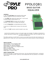
Panel overview of the D12
1 LCD screen
This displays the volume (level meters) and time
locations (locate) during recording or playback,
and displays the various parameters. (→p.13)
2 [TRACK STATUS] keys
These keys are used to put each track into play-
back, record, or to mute (silence) status. Each time
you press a key, the track setting will alternate.
(→p.111)
Green: PLAY
Orange: INPUT
Red: REC
Dark: MUTE
When recording from analog/digital input, you
can select up to four recording tracks.
These settings can be paired.
3 [PAN] knobs (Ch 1…6)
[BALANCE] knobs (Ch 7…12)
These knobs adjust the stereo location of each chan-
nel.
For channels 1–6 they adjust the pan of each chan-
nel. For channels 7–12 they adjust the balance.
(→p.111)
These settings can be paired, and registered in
a scene.
4 [CHANNEL] faders (Ch1…6, Ch7/8…11/12)
These faders adjust the recording/playback vol-
ume of each channel.
Channels 7–12 are stereo faders. (→p.112)
These settings can be paired, and registered in
a scene.
5 [MASTER] fader
This adjusts the volume of all channels. During
bounce recording, this sets the recording level of
the bounce destination track. (→p.112)
6 TRANSPORT keys
[REC] key, [RHSL] key, [PLAY] key, [STOP] key,
[REW] key, [FF] key
These are used to perform recorder operations such
as playback and record. (→p.112)
7 [VALUE] dial
This is used to modify parameter values, and to
move the current time.
When the Scrub function is on, rotating the dial
will cause the track to play at the corresponding
speed.
Top panel
1
2
3
4
5
8
7
6
9
12 ~ 32
1011
* For the mic and trim controls etc., refer to the “Front panel” section.

9
8 [CURSOR] key
This key moves the cursor.
9 [POWER] key
This key turns the power on/off. (→p.17)
10 HDD/CD access indicator
This indicator will light when the internal hard
disk is being accessed for recording or playback, or
when the internal CD-R/RW drive is operating.
Never move the D12 or apply physical shock to it
when this HDD/CD access indicator is lit.
11 MIDI indicator
This indicator will light when MIDI messages are
received from the MIDI IN connector.
12 [INPUT/TUNER] key
This key is used to select the mixer channel to
which the audio signal from each input jack will be
sent. (→p.23)
This is also used when adjusting the EQ (for
recording) that is applied to the analog inputs.
(→p.102)
In addition, this key is used to access the tuner.
(→p.103)
13 [EQ/PHASE] key
This key is used to specify the EQ (for track play-
back) and phase of each channel. (→p.37, 104)
These settings can be paired, and registered in
a scene.
14 [INSERT EFFECT] key
This key is used to select the location of an insert
effect, to select the effect type, and to select and edit
effect programs. (→p.43, 105)
These settings can be registered in a scene.
15 [MASTER EFFECT/AUX] key
This key is used to select and edit effect programs
for master effects 1 and 2, and to set the send levels
from each channel to the master effects. In addi-
tion, it is used to set the send amount to an external
effect, and to select and edit effect programs for the
final effects. (→p.45, 107)
These settings can be registered in a scene. The
send settings can be paired.
16 [SOLO/MONITOR] key
This key is used to solo an individual channel,
send, or return. It is also used to select an audio
source for monitoring. (→p.109)
When solo is on, the LED will blink.
17 [METER/TRACK VIEW] key
This key is used to display volume data (level
meters) during recording and playback, and to
view audio event data in each track (track view).
(→p.111)
18 [SYSTEM] key
This key is used to make foot switch and MIDI-
related settings, to manage data on disk, and to
backup or restore data. (→p.75)
19 [RECORD] key
Press this key to make recorder settings such as
selecting the recording source or the bounce
recording method etc. (→p.80)
20 [TRACK] key
This key is used to select the virtual track for each
track, to perform track editing operations such as
copy or delete, and when importing or exporting
WAV files. (→p.81)
21 [SONG/CD] key
Press this key to create a new song, rename/select
a song, perform a song editing operation such as
copy or move, perform program playback of songs,
or produce an audio CD (a CD-R/RW drive is
required). (→p.88)
22 [STORE] key
Press this key to register the time location for a
locate point, a mark, or a scene. (→p.35, 91)
23 [MARK] key
Register the desired time location in a song as a
Mark, so that the registered time can be recalled
instantly.
It is also used to edit marks by renaming or delet-
ing them etc. (→p.36, 92)
24 [SCENE] key
This key is used to register [CHANNEL] fader,
[PAN]/[BALANCE] knob, EQ or effect send set-
tings as a scene at the specified time location in a
song. If the Scene Read setting is on during play-
back, the registered scenes will be selected auto-
matically at the corresponding times. Scenes can
also be sorted, renamed, or deleted. (→p.39, 92)
This key will light when Scene Read is “On.”
25 [TEMPO/RHYTHM] key
This key is used to set the tempo for a song, create a
tempo map, and turn the rhythm function on/off.
(→p.61, 94)
This key will light when the Rhythm function is on.
26 [IN/LOC1] key, [OUT/LOC2] key, [TO/LOC3] key,
[END/LOC4] key
These keys are used to register a desired time loca-
tion within a song, or to instantly jump to a regis-
tered time location.
The time locations registered here are used as the
punch-in/out locations, and the editing range for
track editing operations such as copy or delete.
12
13
14
15
16
17
18
22
26
29
28
27
30 31
32
19
23
20
24
21
25
Introduction
Panel overview of
the D12

10
(→p.35, 97)
By holding down the [IN/LOC1] key and pressing
the [OUT/LOC2] key, you can listen to the audio
between the IN–OUT points.
27 [AUTO PUNCH] key
This key is used to turn the Auto Punch-in/out
function on/off, to set the pre/post roll time, and
to verify the start/end locations. (→p.28, 98)
This key will light when the Auto Punch-in/out
function is on.
28 [LOOP] key
This key is used to turn the Loop function on/off
for playback or recording, and to verify the start/
end locations. (→p.99)
This key will light when the Loop function is on.
29 [UNDO] key
After recording or editing a track, you can use the
Undo function to return the data to its prior state,
and then (if desired) use the Redo function to can-
cel the Undo and go back to the edited data.
Up to 99 prior recording or editing operations can
be undone. You can select from 1, 8, or 99 levels of
undo. (→p.99)
This key will light when Undo or Redo is available.
30 [TRIGGER] key
This is the on/off key for the Trigger Recording
function, which causes recording to begin automat-
ically in response to an audio input. This key is also
used to set the threshold level and pre-trigger time.
(→p.31, 100)
This key will light when the Trigger Recording
function is on.
31 [SCRUB] key
This key turns the Scrub, Play To/From, and Slow
Play functions on/off. The key will light when the
Scrub function is “On.” These functions are used
by controlling the [VALUE] dial or TRANSPORT
keys. (→p.101)
32 [ENTER] key
This key is used to finalize a parameter selection, or
to turn a parameter on/off.
1 MIC (built-in mic)
2 [MIC] on indicator
3 [MIC] switch: OFF, INPUT 1, INPUT 2
OFF: The built-in mic is turned off. (LED dark)
INPUT 1: The built-in mic is input from [INPUT 1].
(LED lit)
INPUT 2: The built-in mic is input from [INPUT 2].
(LED lit)
When the [MIC] switch is set of the INPUT 1 or
INPUT 2, that input will used as the mic input, and
the source connected to that jack will not be input.
The input priority order is as follows.
• 1 [MIC], 2 [GUITAR IN], 3 [INPUT]
If you are not using the internal mic, turn the [MIC]
switch off so that unwanted sound is not input
from the mic.
4 [GUITAR IN] jack
A guitar or bass guitar can be plugged in here.
This is an unbalanced 1/4" (6.3 mm) input jack
with 1 M-ohm impedance.
5 [INPUT 1], [INPUT 2] jacks
Audio sources such as mic or line (keyboard etc.)
can be connected here.
These are combo-type balanced inputs that com-
bine XLR jacks and 1/4" TRS phone jacks.
Unbalanced phone plugs can also be connected.
If you connect a plug to the [GUITAR IN] jack, no
input signal will be received from the [INPUT 1]
jack. If you wish to use the [INPUT 1] jack, discon-
nect the plug from the [GUITAR IN] jack.
1
2
9
7
3
46810115
Front panel
1/4" TRS phone jack
XLR jack
1: GND
2: HOT
3: COLD
3
1
2
Balanced phone plug Unbalanced phone plug
GND COLD HOT
GND HOT

11
6 [INPUT 3], [INPUT 4] jacks
Mic/line (e.g., keyboard) sources can be input here.
These are balanced 1/4" TRS phone jacks. Unbal-
anced phone jacks can also be connected.
7 [TRIM] knob: –60...–10...+4 dBu
These knobs adjust the input level. The markings
indicate the input level.
Adjust each [TRIM] knob as appropriate for the
input instrument, so that the peak indicator lights
when the connected instrument is played most
loudly.
The input level will depend on the instrument or
performance, but the approximate ranges are as
follows.
–60 – –40 dBu: mic input
–30 dBu: guitar, bass guitar
–10 dBu: consumer audio devices such as a CD
player
+4 dBu: keyboards or studio equipment
If the [TRIM] knob is raised when nothing is con-
nected to an input, hum or noise may result.
8 [PHONES] jack
A set of headphones can be connected here.
This is a 1/4" stereo phone jack.
This outputs the same signal as the [MONITOR
OUT L/R] jacks.
9 [PHONES LEVEL] knob: 0...10
This knob sets the volume level of the headphones.
The volume will increase in correspondence to the
printed grad.
10 [FOOT SWITCH] jack
When your hands are occupied with playing an
instrument, you can use a foot switch to control
basic operation of the recorder section.
A foot switch can be used to start/stop the play-
back, start/end manual punch-in recording, to reg-
ister a mark, or to record tap tempo. (→p.75)
Connect the foot switch (such as the optional PS-1)
to this jack.
11 [EXPRESSION PEDAL] jack
You can use a pedal to control a specified parame-
ter of an insert effect. You can control the parameter
in realtime while you play or record. (→p.47)
Connect an expression pedal (separately sold
option, EXP-2, XVP-10 etc.) to this jack.
1 [AC 9V] connector
Connect the included AC/AC power supply to this
connector.
2 [MIDI OUT] connector
MIDI messages are transmitted from this connec-
tor. Use this when you wish to control a connected
external MIDI device from the D12. (→p.73)
3 [MIDI IN] connector
MIDI messages are received at this connector. Use
this when you wish to control the D12 from a con-
nected external MIDI device. (→p.73)
4 [LCD CONTRAST] knob
This adjusts the contrast of the LCD screen.
The optimal setting will depend on the viewing
angle, so adjust the contrast as necessary. Looking
from the front panel, turning the knob toward the
right will darken the text, and turning it toward the
left will lighten the text.
5 [SCSI] connector
An external hard disk drive, or removable disk
drive can be connected here, and used for record-
ing/playback in the same way as the internal
drive. An external drive can also be used for
backup. (→p.67)
In addition, a CD-R/RW drive can be connected
here to create an audio CD or to make backups.
(→p.49, 67)
This is a HD SCSI-2 (50 pin SCSI) connector.
For details on the SCSI devices that can be used
with the D12, please refer to the Korg website or
contact Korg distributor.
6 [AUX OUT] jack
This jack outputs the external send signal from
each mixer channel. (The send amount is adjusted
in the [MASTER EFFECT/AUX] “AuxSnd” tab
page.) Connect this jack to your external effect pro-
cessor.
This is a 1/4" phone jack.
7 [MONITOR OUT L/R] jacks
Connect your external monitor system to these
jacks. The bus that is sent to the monitor output is
selected in the [SOLO/MONITOR] “Monitor” tab
page. (→p.109) These jacks output the same audio
signal as [PHONES].
These are RCA phono jacks.
Rear panel
1234 5 1011 9876
Introduction
Panel overview of
the D12

12
8 [MONITOR OUT LEVEL] knob
This knob sets the volume level from the [MONI-
TOR OUT L/R] jacks.
9 [MASTER OUT L/R] jacks
These are analog outputs for the master LR bus
which combines the signals from each mixer chan-
nel, or for the audio source that is selected by the
Solo function. The Solo selection is made in the
[SOLO/MONITOR] “Solo” tab page.
Connect your external monitor system or recording
device to these jacks. They output the same audio
signal as the [S/P DIF OUT] jacks.
These are RCA phono jacks.
10 [S/P DIF OUT] jack
This is an optical-type S/P DIF format (IEC60958,
EIAJ CP-1201) digital output jack (stereo).
Use an optical cable to connect this jack to the opti-
cal digital input of your DAT or MD.
This jack digitally outputs the same audio signal as
the [MASTER OUT L/R] jacks at a sampling rate of
44.1 kHz.
11 [S/P DIF IN] jack
This is an optical-type S/P DIF format (IEC60958,
EIAJ CP-1201) digital input jack (stereo).
Use an optical cable to connect this jack to the opti-
cal digital output of your DAT or MD.
A sampling rate converter is built in. If the con-
nected source has a sampling rate of 48 kHz or 32
kHz source, it will be converted automatically to
44.1 kHz.
1 CDRW-1 drive bay
A separately sold CDRW-1 CD-R/RW drive option
can be installed in this bay. (→p.133)
Side panel
1

13
Objects in the LCD screen and their
functions
To select an object displayed in the LCD screen, use the
[CURSOR] key to select it, and press the [ENTER] key.
In this manual, terms enclosed in “quotation
marks” such as “...”, “...” button, or “...” tab refer to
objects in the LCD screen which you can operate.
Terms enclosed in square brackets such as [...] key,
[...] knob, [...] dial, or [...] fader refer to controls etc.
located on the top panel, front panel, or rear panel.
a: Current parameter display
This is the name of the parameter currently selected by
the edit cell.
For icon-type parameters such as EQ or fader, the value
is displayed at the right.
b: Edit cell
When you select a parameter in the LCD screen, the
parameter value will be highlighted in some cases. This
area is referred to as the edit cell, and your editing will
apply to the highlighted portion.
The parameter value in the edit cell can be modified
using the [VALUE] dial (→p.8) or by using the popup
buttons in the LCD screen.
c: Popup button
When you select this button and press the [ENTER] key,
a dialog box (f) will appear.
To enter a parameter value, choose the desired value
from the dialog box.
, ,
d: Toggle button
This type of button will turn the corresponding func-
tion on/off each time you press the [ENTER] key.
(on)/ (off)
e: Tab page
Each mode contains numerous parameters, which are
organized into pages. Each page is accessed by its own
tab.
f: Dialog box
Select the “OK” button to execute the function (or select
the “Cancel” button to cancel without executing), and
press the [ENTER] key. The dialog box will close.
g: Radio buttons
These buttons are used to select one of multiple items.
Select one radio button and press the [ENTER] key.
h: Icons
These are objects shaped like sliders or knobs. To mod-
ify a value, select it and rotate the [VALUE] dial.
i: Scroll buttons
These buttons are used to view parameter values that
cannot be displayed in a single screen.
Objects in the LCD screen
e: Tab
a:Current parameter
display
c:Popup
button
d:Toggle
button
b: Edit cell
g: Radio buttons f: Dialog box
h: Icons
i: Scroll buttons
Introduction
Objects in the LCD screen and
their functions

14
Use the rear panel [LCD CONTRAST] knob to adjust
the contrast. (→p.11)
1. Selecting a mode
To make settings in the LCD screen for the various
functions of the D12, you must first press the key of the
mode that includes that function.
For the functions of each mode, refer to “Reference”
(→p.75–).
2. Selecting a tab page
Each mode contains numerous parameters, and these
are organized into pages. Pages are accessed by tabs.
1 Press the key for the desired mode.
The illustration below shows a page of TEMPO/
RHYTHM mode that will appear when you press
the [TEMPO/RHYTHM] key.
2 Select the desired tab page.
Each time you press the key of the currently
selected mode, you will cycle through the tab
pages of that mode.
Some pages contain only one tab.
3. Selecting and setting a parameter
Selecting a parameter
To edit a parameter, use the [CURSOR] key to move the
edit cell to the parameter that you wish to edit, high-
lighting that parameter.
In a list display screen, you can rotate the [VALUE] dial
to move the edit cell.
Setting a parameter value
The method of setting a parameter value will differ
depending on the type of parameter.
● Underlined “___” parameters, and icons such as
EQ
Use the [CURSOR] key to move the edit cell to the
parameter, highlighting it, and rotate the [VALUE]
dial to set the value.
This is the usual type, and includes underlined
parameters such as “T
empo,” parameters repre-
sented by an icon such as EQ, and also Locate times
to be adjusted.
● Popup buttons and dialog boxes
Use the popup button to access the dialog box, and
set the parameter value (→p.13).
• Use the [CURSOR] key to move the edit cell to
the popup button, and press the [ENTER] key to
access the dialog box.
● Toggle buttons
These buttons are used to turn a function on/off.
(→p.13)
• Use the [CURSOR] key to select the parameter,
and press the [ENTER] key. The button will turn
on/off each time you press it.
● Radio buttons
These buttons are used to select one of multiple
choices.
• Use the [CURSOR] key to move the edit cell to
the desired button, and press the [ENTER] key.
● Selecting an item from a list
• To select a song or mark, rotate the [VALUE]
dial to select the desired item.
• To select a song in a program play list, use the
following procedure.
1 Select the playback list num.
2 Rotate the [VALUE] dial to select the song.
Adjusting the LCD screen con-
trast
Basic operation

Basic operation
Making connections, and
turning the power on/off
Creating/selecting
a song
Assign audio inputs
to the mixer
RecordingPlayback
Changing the
time location
Using the mixerUsing effects
Mixdown
Track editingSong editing
Rhythm/tempo settings
Saving your data
MIDI Starting
15
Basic operation
Step 0. Starting
1. Using the D12
The D12 lets you record your own performance and
shape it into a completed song.
If a separately sold CDRW-1 CD-R/RW drive option is
installed in the D12, you can easily create an original
CD.
Connecting instruments and turning on the
power
Connect the instrument and mic etc. that you wish to
use for recording to the D12, and turn on the power.
(→p.17)
Create a song
First you will create a song, and assign a song title.
If you will be creating a CD, set the song type to 16 bit.
The title can be assigned later. (→p.21)
Recording
Successively record the melody, bass, and drums etc. on
tracks 1–12.
This process is the same as when using analog tape
multi-track recorders such as a multi-track cassette, but
the important difference is that on the D12, you can use
numerous convenient functions, such as the Undo
function to cancel a mistake you made, the Auto
Punch-in/out function to re-record a specific area that
you wish to fix, or Trigger Recording to automatically
start recording as soon as you begin playing your
instrument. You can also take advantage of the D12’s
virtual tracks to record and edit using more than 12
tracks. In addition, you can use the internal rhythm
sounds as a tempo guide, or apply the internal effects
as you record. (→p.27)
Mixdown
In this step, you can apply EQ and effects to the sound
of each recorded track, adjust the volume and pan, and
combine the tracks into two tracks. (→p.49)
By applying the built-in Final Effect to the MASTER L/
R, you can add finishing touches to your song. When
you have finished adjusting the balance, use “12Tr →
2Tr bounce” to mix the song down to two tracks.
At this time if you record the mixdown on virtual
tracks other than the current virtual tracks (i.e., the
tracks selected for recording and playback), you will be
able to record and compare between up to seven differ-
ent mixdowns. (→p.30)
Writing your song to CD
In this step, the song you mixed down to tracks 1 and 2
can be written to a CD.
Play back tracks 1 and 2 to hear the result of your mix-
down. Tracks 1 and 2 will be written to the CD. Simply
insert a new CD-R disc into the drive, select the
“WriteToCD” button, and press the [ENTER] key to
write your song to CD.
You can create an album by using the same procedure
to write each new song to the CD.
When you are finished, select the “Final” button and
press the [ENTER] key to finalize the CD. This com-
pletes your own original CD. (→p.49)

16
Connect
instruments and
turn on the power
Create a new song
Record
Mixdown
Creating an audio
Assign mixer channels
• Apply effects to the input sound (Step 8)
• Apply EQ
Adjust the track balance
• Apply effects to the tracks
• Apply EQ to the tracks
• Apply master effects
Write the song to CD
Finalize
Bounce to tracks 1 and 2
Editing
• Track editing
• Punch-in/out
Overdubbing
Playback
Recording
Adjust the recording level
Scenes
• Registering a scene
• Playing a scene
→Step 1
→Step 2
→Step 3
→Step 4
→Step 9
→Step 7
→Step 7
→Step 8
→Step 4
→Step 9
→Step 4
→Step 5
→Step 10
Final effect

17
Step 1. Making connections, and turning
the power on/off
1. Connections
Make the appropriate connections for your system,
substituting your own equipment as necessary for the
equipment shown here.
The diagram below shows a basic example of connec-
tions when using the D12 to record.
For details on installing the CDRW-1 CD-R/RW
drive option, refer to p.133.
Be sure that the power is turned off while you are
making connections. If the power is on while con-
nections are being made, your speaker system may
be damaged, or other malfunctions may occur.
1 Connect the included AC/AC power supply.
Connect the AC/AC power supply to the AC/AC
power supply connector of the D12. Then plug the
other end into an AC outlet.
2 Connect your audio monitoring system.
Use RCA phono cables to connect a powered moni-
tor system etc. to the [MONITOR OUT L/R] jacks.
If you will be monitoring through headphones,
connect the 1/4" phone plug of your headphones
to the [PHONES] jack.
Use the [PHONES LEVEL] knob to adjust the vol-
ume.
The audio signal that is output from the [MONI-
TOR OUT L/R] jacks and the [PHONES] jack is set
in the [SOLO/MONITOR] “Monitor” tab page.
(→p.109)
3 Connect your input devices.
Connections for recording analog sources
• Guitar, bass guitar ↔ [GUITAR IN] jack
• Mic (XLR) ↔ [INPUT 1], [INPUT 2] jacks
• Synthesizer etc. ↔ [INPUT 1]–[INPUT 4] jacks
For details on assigning the audio inputs to mixer
channels and auditioning the input sound, refer to
p.23.
[PHONES LEVEL] knob
[PHONES] jack
INPUT L/R
PHONES
FOOT SWITCH
EXPRESSION
PEDAL
S/P DIF IN
DIGITAL IN
DIGITAL OUT
S/P DIF OUT
OUTPUT
GUITAR IN
INPUT
1–4
MIDI
IN/OUT
MIDI
OUT/IN
MONITOR
OUT L R
MASTER
OUT L R
SCSI
SCSI
Powered monitors etc.
Guitar
PS-1
Pedal switch
Keyboard
Mic
Headphones
to the AC outlet
Power supply connection
You must use the
included AC/AC power
supply
AC/AC power
supply connector
MIDI
sequencer
Master recorder (Digital: DAT, MD, etc.)
Master recorder (Analog: cassette tape recorder, etc.)
Hard disk drive, CD-R/RW drive
removable disk drive (MO, zip, jaz etc.)
EXP-2 Foot controller
CDRW-1
CD-R/RW
Drive option
Basic operation
Making connections, and
turning the power on/off

18
A guitar or bass guitar that is being sent
through a compact effect device can be con-
nected to [INPUT 1]–[INPUT 4].
When inputting in stereo, you should select
two adjacent inputs (1–2, 3–4) so that track
editing can be performed more efficiently.
If you are recording from a connected mic,
locate the mic at a sufficient distance from the
D12 so that it does not pick up noise.
Connections for recording digital sources
• Optical digital (S/P DIF) output of a digital out-
put device such as DAT or MD ↔ [S/P DIF IN]
connector of the D12 (use an optical digital cable
for connection)
For details on assigning the audio inputs to mixer
channels and auditioning the input sound, refer to
p.23.
4 Make other connections.
Connections for mixdown
Here’s how to make connections when the song
created on the D12 will be mixed down on an exter-
nal recording device (DAT, MD, tape recorder, etc.)
• Optical digital (S/P DIF) input of a digital
recording device such as DAT or MD ↔ [S/P
DIF OUT] of the D12
• AUX IN inputs of an analog recording device
such as a cassette tape recorder ↔ [MASTER
OUT L/R] jacks of the D12
Connections when using external effects
If you wish to apply an external effect to the signal
from [AUX OUT] send output, use the [INPUT 1]–
[INPUT 4] jacks to receive the return signal(s).
In this case, you can choose whether the signal(s)
will be returned to the mixer channel(s) in the same
way as a conventional input, or sent directly to the
master bus. (→p.48)
Connections when using a foot switch to perform
manual punch recording, or playback/stop etc.
Connect the pedal switch (separately sold option:
PS-1) to the [FOOT SWITCH] jack.
Connections when using a foot pedal to control
effects
Connect the expression pedal (separately sold
option: EXP-2, XVP-10) to the [EXPRESSION
PEDAL] connector.
If a volume pedal is connected, it will not oper-
ate correctly.
Connections when controlling effects or switching
scenes from an external MIDI device
Connect the MIDI OUT connector of the external
MIDI device ↔ [MIDI IN] connector of the D12.
(→p.73)
Connections when synchronizing the D12 and a
MIDI sequencer etc.
Connect the MIDI IN connector of the sequencer
etc. ↔ [MIDI OUT] connector of the D12. (use a
MIDI cable)
Connect the MIDI OUT connector of the sequencer
etc. ↔ [MIDI IN] connector of the D12. (→p.73)
Connections when saving or backing up data on an
external hard disk or removable disk
SCSI connector of the external SCSI device ↔
[SCSI] connector of the D12 (use a SCSI cable to
make connections). (→p.67)
2. Turning the power on/off
Turning the power on
Use the following procedure to turn on the power of
the D12 and of the devices connected to it.
Before turning the power on, be sure to lower the
volume of each device to the minimum position,
and turn the devices on beginning with the first
device in the signal chain (i.e., devices that produce
audio signals).
1 Lower the D12’s [MASTER] fader to the –∞
position.
Also turn down the volume of each connected
device.
2 Turn on the power of the external input
device, such as a keyboard connected to the
D12.
If an external drive is connected, turn on the
power of the external drive.
3 Press the [POWER] key of the D12 to turn on the
power.
The LCD screen will show the opening
message, and then the [SONG] “Sel-
Song” tab page will appear.
The song that had been selected when the
power was last turned off will be selected.
4 Turn on the power of the devices to which audio
signals are being sent from the D12, such as your
monitor system or MD recorder.
Turning the power off
When you are finished playing or recording a song,
turn off the power. Use the following procedure to turn
off the power of the D12 and of the connected devices.
About the power switch of the AC/AC power supply
• When turning off the power of the recorder, you
must first turn off the [POWER] switch of the
recorder itself.
If you turn off the power switch of the AC/AC
power supply first, the recorded data and user set-
tings will be lost.
• Never turn off the power switch of the AC/AC
power supply while the recorder is operating.
Doing so may cause part or all of the data on the
internal hard disk drive to be lost, or the hard disk to
be damaged.
Before turning off the power, turn the volume of all
devices down to the minimum position, and turn
off the power switches beginning with the devices
that are at the end of the audio signal chain.
Never disconnect the AC/AC power supply until
the power is completely off. Data may be destroyed
if you do so.
/