Page is loading ...

Motherboard
P4B533-X
User Guide

ii
Checklist
Copyright © 2003 ASUSTeK COMPUTER INC. All Rights Reserved.
No part of this manual, including the products and software described in it, may be
reproduced, transmitted, transcribed, stored in a retrieval system, or translated into any
language in any form or by any means, except documentation kept by the purchaser for
backup purposes, without the express written permission of ASUSTeK COMPUTER INC.
(“ASUS”).
Product warranty or service will not be extended if: (1) the product is repaired, modified or
altered, unless such repair, modification of alteration is authorized in writing by ASUS; or (2)
the serial number of the product is defaced or missing.
ASUS PROVIDES THIS MANUAL “AS IS” WITHOUT WARRANTY OF ANY KIND, EITHER
EXPRESS OR IMPLIED, INCLUDING BUT NOT LIMITED TO THE IMPLIED WARRANTIES
OR CONDITIONS OF MERCHANTABILITY OR FITNESS FOR A PARTICULAR PURPOSE.
IN NO EVENT SHALL ASUS, ITS DIRECTORS, OFFICERS, EMPLOYEES OR AGENTS BE
LIABLE FOR ANY INDIRECT, SPECIAL, INCIDENTAL, OR CONSEQUENTIAL DAMAGES
(INCLUDING DAMAGES FOR LOSS OF PROFITS, LOSS OF BUSINESS, LOSS OF USE
OR DATA, INTERRUPTION OF BUSINESS AND THE LIKE), EVEN IF ASUS HAS BEEN
ADVISED OF THE POSSIBILITY OF SUCH DAMAGES ARISING FROM ANY DEFECT OR
ERROR IN THIS MANUAL OR PRODUCT.
SPECIFICATIONS AND INFORMATION CONTAINED IN THIS MANUAL ARE FURNISHED
FOR INFORMATIONAL USE ONLY, AND ARE SUBJECT TO CHANGE AT ANY TIME
WITHOUT NOTICE, AND SHOULD NOT BE CONSTRUED AS A COMMITMENT BY ASUS.
ASUS ASSUMES NO RESPONSIBILITY OR LIABILITY FOR ANY ERRORS OR
INACCURACIES THAT MAY APPEAR IN THIS MANUAL, INCLUDING THE PRODUCTS
AND SOFTWARE DESCRIBED IN IT.
Products and corporate names appearing in this manual may or may not be registered
trademarks or copyrights of their respective companies, and are used only for identification or
explanation and to the owners’ benefit, without intent to infringe.
E1458
First Edition
November 2003

iii
Features
Contents
Notices ...........................................................................................vi
Safety information ......................................................................... vii
About this guide............................................................................ viii
Conventions used in this guide ........................................... viii
Where to find more information ........................................... viii
P4B533-X specification summary ..................................................ix
Chapter 1: Product introduction
1.1 Welcome! ........................................................................... 1-2
1.2 Package contents............................................................... 1-2
1.3 Special features.................................................................. 1-3
1.3.1 Product highlights .................................................. 1-3
1.3.2 Unique ASUS features ........................................... 1-4
1.4 Before you proceed ............................................................ 1-5
1.5 Motherboard overview........................................................ 1-6
1.5.1 Motherboard layout ................................................ 1-6
1.5.2 Placement direction ............................................... 1-7
1.5.3 Screw holes ........................................................... 1-7
1.6 Central Processing Unit (CPU)........................................... 1-8
1.6.1 Overview ................................................................ 1-8
1.6.2 Installing the CPU .................................................. 1-9
1.7 System memory ............................................................... 1-10
1.7.1 DIMM sockets location......................................... 1-10
1.7.2 Installing a DIMM ..................................................1-11
1.8 Expansion slots .................................................................1-11
1.8.1 Standard interrupt assignments ........................... 1-12
1.8.2 IRQ assignments for this motherboard ................ 1-12
1.8.3 PCI slots .............................................................. 1-13
1.8.4 AGP slot............................................................... 1-13
1.9 Jumpers............................................................................ 1-14
1.10 Connectors ....................................................................... 1-16
1.10.1 Rear panel connectors......................................... 1-16
1.10.2 Internal connectors .............................................. 1-17

iv
Safeguards
Contents
Chapter 2: BIOS information
2.1 Managing and updating your BIOS .................................... 2-2
2.1.1 Creating a bootable floppy disk ............................. 2-2
2.1.2 Using AFUDOS to copy the current BIOS ............. 2-3
2.1.3 Using AFUDOS to update the BIOS ...................... 2-3
2.1.4 Using ASUS EZ Flash to update the BIOS ............ 2-5
2.1.5 Recovering the BIOS with CrashFree BIOS 2 ....... 2-6
2.2 BIOS Setup program .......................................................... 2-8
2.2.1 BIOS menu screen ................................................ 2-9
2.2.2 Menu bar................................................................ 2-9
2.2.3 Navigation keys ..................................................... 2-9
2.2.4 Menu items .......................................................... 2-10
2.2.5 Sub-menu items................................................... 2-10
2.2.6 Configuration fields .............................................. 2-10
2.2.7 Pop-up window .................................................... 2-10
2.2.8 Scroll bar.............................................................. 2-10
2.2.9 General help ........................................................ 2-10
2.3 Main menu.........................................................................2-11
2.3.1 System Time [xx:xx:xxxx]......................................2-11
2.3.2 System Date [Day xx/xx/xxxx] ..............................2-11
2.3.3 Legacy Diskette A [1.44M, 3.5 in.] ........................2-11
2.3.4 Primary and Secondary IDE Master/Slave .......... 2-12
2.3.5 System Information .............................................. 2-13
2.4 Advanced menu ............................................................... 2-14
2.4.1 JumperFree Configuration ................................... 2-14
2.4.2 CPU Configuration................................................ 2-16
2.4.3 Chipset.................. ............................................... 2-16
2.4.4 Onboard Devices Configuration........................... 2-17
2.4.5 PCI PnP ............................................................... 2-20
2.5 Power menu ..................................................................... 2-22
2.5.1 Suspend Mode [Auto] .......................................... 2-22
2.5.2 Repost Video on S3 Resume [No] ....................... 2-22
2.5.3 ACPI 2.0 Support [No] ......................................... 2-22
2.5.4 ACPI APIC Support [Enabled] ............................. 2-22
2.5.5 APM Configuration............................................... 2-23
2.5.6 Hardware Monitor ................................................ 2-24

v
2.6 Boot menu ........................................................................ 2-25
2.6.1 Boot Device Priority ............................................. 2-25
2.6.2 Removable Drives ............................................... 2-26
2.6.3 Boot Settings Configuration ................................. 2-26
2.6.4 Security ................................................................ 2-28
2.7 Exit menu ......................................................................... 2-30
Chapter 3: Software support
3.1 Install an operating system................................................. 3-2
3.2 Support CD information...................................................... 3-2
3.2.1 Running the support CD ........................................ 3-2
3.2.2 Drivers menu ......................................................... 3-3
3.2.3 Utilities menu ......................................................... 3-4
3.2.4 ASUS Contact Information..................................... 3-5
Contents

vi
Notices
Federal Communications Commission Statement
This device complies with Part 15 of the FCC Rules. Operation is subject to
the following two conditions:
• This device may not cause harmful interference, and
• This device must accept any interference received including interference
that may cause undesired operation.
This equipment has been tested and found to comply with the limits for a
Class B digital device, pursuant to Part 15 of the FCC Rules. These limits
are designed to provide reasonable protection against harmful interference
in a residential installation. This equipment generates, uses and can radiate
radio frequency energy and, if not installed and used in accordance with
manufacturer’s instructions, may cause harmful interference to radio
communications. However, there is no guarantee that interference will not
occur in a particular installation. If this equipment does cause harmful
interference to radio or television reception, which can be determined by
turning the equipment off and on, the user is encouraged to try to correct the
interference by one or more of the following measures:
• Reorient or relocate the receiving antenna.
• Increase the separation between the equipment and receiver.
• Connect the equipment to an outlet on a circuit different from that to
which the receiver is connected.
• Consult the dealer or an experienced radio/TV technician for help.
Canadian Department of Communications Statement
This digital apparatus does not exceed the Class B limits for radio noise
emissions from digital apparatus set out in the Radio Interference
Regulations of the Canadian Department of Communications.
This class B digital apparatus complies with Canadian ICES-003.
The use of shielded cables for connection of the monitor to the
graphics card is required to assure compliance with FCC regulations.
Changes or modifications to this unit not expressly approved by the
party responsible for compliance could void the user’s authority to
operate this equipment.

vii
Safety information
Electrical safety
• To prevent electrical shock hazard, disconnect the power cable from
the electrical outlet before relocating the system.
• When adding or removing devices to or from the system, ensure that
the power cables for the devices are unplugged before the signal
cables are connected. If possible, disconnect all power cables from the
existing system before you add a device.
• Before connecting or removing signal cables from the motherboard,
ensure that all power cables are unplugged.
• Seek professional assistance before using an adpater or extension
cord. These devices could interrupt the grounding circuit.
• Make sure that your power supply is set to the correct voltage in your
area. If you are not sure about the voltage of the electrical outlet you
are using, contact your local power company.
• If the power supply is broken, do not try to fix it by yourself. Contact a
qualified service technician or your retailer.
Operation safety
• Before installing the motherboard and adding devices on it, carefully
read all the manuals that came with the package.
• Before using the product, make sure all cables are correctly connected
and the power cables are not damaged. If you detect any damage,
contact your dealer immediately.
• To avoid short circuits, keep paper clips, screws, and staples away from
connectors, slots, sockets and circuitry.
• Avoid dust, humidity, and temperature extremes. Do not place the
product in any area where it may become wet.
• Place the product on a stable surface.
• If you encounter technical problems with the product, contact a
qualified service technician or your retailer.

viii
About this guide
Conventions used in this guide
To make sure that you perform certain tasks properly, take note of the
following symbols used throughout this manual.
Where to find more information
Refer to the following sources for additional information and for product
and software updates.
1. ASUS Websites
The ASUS websites worldwide provide updated information on ASUS
hardware and software products. The ASUS websites are listed in the
ASUS Contact Information on the inside front cover.
2. Optional Documentation
Your product package may include optional documentation, such as
warranty flyers, that may have been added by your dealer. These
documents are not part of the standard package.
WARNING: Information to prevent injury to yourself when trying
to complete a task.
CAUTION: Information to prevent damage to the components
when trying to complete a task.
IMPORTANT: Information that you MUST follow to complete a
task.
NOTE: Tips and additional information to aid in completing a task.

ix
P4B533-X specification summary
CPU
Chipset
Front Side Bus (FSB)
Memory
Expansion slots
Storage
Audio
LAN
USB
Special features
Extreme Overclocking
Rear panel I/O
(continued on the next page)
Socket 478 for Intel
®
Pentium
®
4 / Celeron processors with
speeds up to 3.06GHz+
Intel
®
Hyper-Threading technology ready
Intel 845E MCH
Intel ICH4
800*/533/400 MHz
* Overclocking mode
2 x 184-pin DDR DIMM sockets for up to 2GB memory
Supports PC3200*/PC2700*/PC2100/PC1600 unbuffered
non-ECC DDR DIMMs
* Overclocking feature support PC3200/PC2700
1 x AGP 4X (1.5V only)
4 x PCI
2 x UltraDMA 100/66/33
ADI AD1888 SoundMAX 6-channel audio CODEC
S/PDIF out interface
Realtek 10/100 Mbps Ethernet LAN controller
Supports 6 USB 2.0 ports
ASUS EZ Flash
ASUS CrashFree BIOS2
ASUS MyLogo
ASUS C.P.R (CPU Parameter Recall)
STR (Suspend-To-RAM)
STD (Suspend-To-Disk)
Wake-On-Ring, Wake-On-LAN
Wake-On-Keyboard, Wake-On-Mouse
Support for S/PDIF-out on back of I/O port
ASUS JumperFree
ASUS C.P.R. (CPU Parameter Recall)
SFS (Stepless Frequency Selection) from 100MHz up to
266MHz at 1MHz increment
Adjustable FSB/DDR ratio
AGP/PCI Asynchronous Mode with FSB
1 x Parallel port
1 x Serial port
1 x PS/2 keyboard port
1 x PS/2 mouse port
1 x S/PDIF out port
1 x RJ-45 port
4 x USB 2.0/1.1 ports
Line In/Line Out/Microphone ports

x
P4B533-X specification summary
* Specifications are subject to change without notice.
CPU/Chassis FAN connectors
20-pin ATX power connector
4-pin ATX 12V power connector
GAME/MIDI connector
CD/AUX audio in
Front panel audio connector
1 x USB 2.0 connector supports additional 2 USB 2.0 ports
20-pin Panel connector
3Mb Flash ROM, AMI BIOS, PnP, DMI2.0, WfM2.0, SM
BIOS 2.3, ACPI, ASUS EZ Flash, ASUS MyLogo, ASUS
CrashFree BIOS2, ASUS C.P.R.
PCI 2.2, USB 2.0/1.1
WfM2.0, DMI2.0, WOR by PME, WOL by PME
ATX form factor: 12 in x 7 in (30.5 cm x 17.8 cm)
Device drivers
ASUS PC Probe
ASUS LiveUpdate
Trend Micro™ PC-cillin 2002 anti-virus software (
OEM version)
Internal I/O
connectors
BIOS features
Industry standard
Manageability
Form Factor
Support CD contents

Chapter 1
This chapter describes the features of the
motherboard. It includes brief descriptions of the
motherboard components, and illustrations of the
layout, jumper settings, and connectors.
Product introduction

1-2
Chapter 1: Product introduction
1.1 Welcome!
Thank you for buying the ASUS
®
P4B533-X motherboard!
The motherboard incorporates the Intel
®
Pentium
®
4 processor in a 478-pin
package coupled with the Intel
®
845E chipset to set a new benchmark for an
effective desktop platform solution.
Before you start installing the motherboard, and hardware devices on it, check the
items in your package with the list below.
1.2 Package contents
Check your motherboard package for the following items.
If any of the above items is damaged or missing, contact your retailer.
ASUS motherboard
ASUS motherboard support CD
80-conductor UltraATA IDE cable
Ribbon cable for a 3.5-inch floppy drive
I/O shield
Bag of extra jumper caps
User Guide

ASUS P4B533-X motherboard user guide
1-3
1.3 Special features
1.3.1 Product highlights
Latest processor technology
The motherboard supports the latest Intel
®
Pentium
®
4 or Celeron processor via a
478-pin surface mount ZIF socket. The Pentium 4 processor with 512KB L2 cache on
0.13 micron processor includes a 800*/533/400 MHz system bus, Intel
®
Hyper-
Threading Technology and the FMB2 power design that allows up to 3.06+ GHz
core frequencies for up to 6.4GB/s data transfer rates. (* Overclocking mode) See
page 1-8.
Integrated 10/100 LAN
The onboard LAN controller is a highly integrated Fast Ethernet controller. It is
enhanced with an ACPI management function to provide efficient power
management for advanced operating systems. See page 1-16.
Extreme Overclocking
The motherboard offers robust overclocking options to maximize your system
performance. Overclocking features include: the SFS (Stepless Frequency
Selection) feature, an adjustable FSB/DDR ratio and the ASUS C.P.R. (CPU
Parameter Recall).
6 USB 2.0 ports
The motherboard implements the new Universal Serial Bus (USB) 2.0
specification, extending the connection speed from 12 Mbps on USB 1.1 to a fast
480 Mbps on USB 2.0. The higher bandwidth of USB 2.0 allows connection of
devices such as high resolution video conferencing cameras, next generation
scanners and printers, and fast storage units. USB 2.0 is backward compatible with
USB 1.1. See page 1-19.
6-channel audio
The ADI AD1888 SoundMAX AC ‘97 audio CODEC is onboard to provide 6-
channel audio playback for 5.1 surround sound, over 90dB dynamic range, and
stereo Mic PREAMP. See pages 1-16, 3-3.
S/PDIF out
The motherboard supports S/PDIF out function turns your computer into a high-
end entertainment system with digital connectivity to powerful sound systems. See
page 1-16, 3-3.

1-4
Chapter 1: Product introduction
1.3.2 Unique ASUS features
CrashFree BIOS 2
This feature allows you to restore the original BIOS data from a floppy disk or
support CD in case when the BIOS codes and data are corrupted. This protection
eliminates the need to buy a replacement ROM chip. Page 2-6.
ASUS MyLogo™
This new feature present in the motherboard allows you to personalize and add
style to your system with customizable boot logos. To use the MyLogo feature,
enable the Quick Boot item in the BIOS. See page 3-4.
C.P.R. (CPU Parameter Recall)
The C.P.R. feature of the motherboard BIOS allows automatic re-setting to the
BIOS default settings in case the system hangs due to overclocking. When the
system hangs due to overclocking, C.P.R. eliminates the need to open the system
chassis and clear the RTC data. Simply shut down and reboot the system, and
BIOS automatically restores the CPU’s previous setting for each parameter. See
page 1-14.
ASUS EZ Flash BIOS
With the ASUS EZ Flash, you can easily update the system BIOS even before
loading the operating system. No need to use a DOS-based utility or boot from a
floppy disk. See page 2-5.

ASUS P4B533-X motherboard user guide
1-5
1.4 Before you proceed
Take note of the following precautions before you install motherboard components
or change any motherboard settings.
1. Unplug the power cord from the wall socket before touching any
component.
2. Use a grounded wrist strap or touch a safely grounded object or to a metal
object, such as the power supply case, before handling components to
avoid damaging them due to static electricity.
3. Hold components by the edges to avoid touching the ICs on them.
4. Whenever you uninstall any component, place it on a grounded antistatic
pad or in the bag that came with the component.
5. Before you install or remove any component, ensure that the ATX
power supply is switched off or the power cord is detached from the
power supply. Failure to do so may cause severe damage to the
motherboard, peripherals, and/or components.
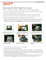
Onboard LED
The motherboad comes with a stand-by power LED. When lit, the green LED
indicates that the system is ON, in sleep mode, or in soft-off mode, a reminder that
you should shut down the system and unplug the power cable before removing or
plugging in any motherboard component. The illustration below shows the location
of the onboard LED.
P4B533-X
®
P4B533-X Onboard LED
SB_PWR1
ON
Standby
Power
OFF
Powere
d
Off

1-6
Chapter 1: Product introduction
1.5 Motherboard overview
1.5.1 Motherboard layout
PCI1
PANEL1
P4B533-X
®
CD1
AUX1
Super
I/O
3Mbit
BIOS
Accelerated Graphics Port (AGP)
CPU_FAN1
FP_AUDIO1
GAME1
FLOPPY1
PRI_IDE
SEC_IDE
ATX Power Connector
DDR DIMM1 (64 bit,184-pin module)
CHA_FAN1
SB_PWR1
USB56
CR2032 3V
Lithium Cell
CMOS Power
USBPW34
CLRTC
USBPW56
DDR DIMM2 (64 bit,184-pin module)
USBPW12
Intel
82845E
MCH
AD1888
PS/2KBMS
T: Mouse
B: Keyboard
USB1
USB2
PARALLEL PORT
SPDIF_O
COM1
Below:Mic In
Center:Line Out
Top:Line In
USB2.0
T: USB4
B: USB3
Top:
RJ-45
PCI2
PCI3
PCI4
Intel
82801DE
ICH4
ATX12V1
Socket 478
RTL
8101L

ASUS P4B533-X motherboard user guide
1-7
Do not overtighten the screws! Doing so may damage the motherboard.
1.5.2 Placement direction
When installing the motherboard, make sure that you place it into the chassis in
the correct orientation. The edge with external ports goes to the rear part of the
chassis as indicated in the image below.
1.5.3 Screw holes
Place seven (7) screws into the holes indicated by circles to secure the
motherboard to the chassis.
Place this side towards
the rear of the chassis

1-8
Chapter 1: Product introduction
1.6 Central Processing Unit (CPU)
1.6.1 Overview
The Intel
®
Pentium
®
4 Northwood/Willamette/Prescott processors has a gold
triangular mark on one corner. This mark indicates the processor Pin 1 that should
match a specific corner of the CPU socket.
Incorrect installation of the CPU into the socket may bend the pins and
severely damage the CPU!
P4B533-X
®
P4B533-X Socket 478
Gold Arrow
Notes on Intel
®
Hyper-Threading Technology
1. This motherboard supports Intel
®
Pentium 4 CPUs with Hyper-Threading
Technology. The motherboard automatically detects an installed Intel
Pentium 4 CPU with Hyper-Threading Technology support.
2. To verify the Hyper-Threading feature, go to the Windows OS System
Properties -> Hardware -> Device Manager -> Processors. The list
should display two existing processors.
3. Hyper-Threading Technology is supported under Windows
®
XP™ and later
versions only.
4. It is recommended that you install Windows
®
XP™ Service Pack 1.
5. For more information on Hyper-Threading Technology, visit
www.intel.com/info/hyperthreading.

ASUS P4B533-X motherboard user guide
1-9
1.6.2 Installing the CPU
Follow these steps to install a CPU.
1. Locate the 478-pin ZIF socket on the motherboard.
2. Unlock the socket by pressing the
lever sideways, then lift it up to a 90°-
100° angle.
Make sure that the socket lever is
lifted up to 90°-100° angle,
otherwise the CPU does not fit in
completely.
3. Position the CPU above the socket
such that its marked corner matches
the base of the socket lever.
4. Carefully insert the CPU into the
socket until it fits in place.
The CPU fits only in one correct
orientation. DO NOT force the
CPU into the socket to prevent
bending the pins and damaging
the CPU!
5. When the CPU is in place, push down
the socket lever to secure the CPU.
The lever clicks on the side tab to
indicate that it is locked.
6. Install a CPU heatsink and fan
following the instructions that came
with the heatsink package.
7. Connect the CPU fan cable to the
CPU_FAN1 connector on the
motherboard.
Socket Lever
90 -10
0
Gold Mark

1-10
Chapter 1: Product introduction
Obtain DDR DIMMs only from ASUS qualified vendors. Visit the ASUS website
(www.asus.com) for the latest QVL.
1.7 System memory
1.7.1 DIMM sockets location
The following figure illustrates the location of the DDR DIMM sockets. You may
install 64MB, 128MB, 256MB, 512MB, and 1GB unbuffered DDR DIMMs into this
motherboard.
P4B533-X
®
P4B533-X 184-Pin DDR DIMM Sockets
80 Pins104 Pins
DIMM1
DIMM2
1. Make sure to unplug the power supply before adding or removing DIMMs or
other system components. Failure to do so may cause severe damage to
both the motherboard and the components.
2. When installing long AGP cards, it is recommended to install the memory
modules first. Long AGP cards, when installed, may interfere with the
memory sockets.
It is recommended to populate only one DIMM slot when using
FSB800/DDR400, FSB800/DDR300 and FSB533/DDR355 overlocking
mode features.
Table 1 Memory frequency/CPU FSB synchronization
This motherboard supports different memory frequencies depending on the CPU
FSB (Front Side Bus) and the type of DDR DIMM.
CPU FSB DDR DIMM Type Memory Frequency
800 MHz* PC3200/PC2700* 400/333* MHz
533 MHz PC3200**/PC2700**/PC2100/PC1600 400**/333**/266/200 MHz
400 MHz PC2100/PC1600 266/200 MHz
* When using 800MHz CPU FSB, PC2700 DDR DIMMs run only at 300MHz (not 333MHz)
** When using 533MHz CPU FSB, PC3200/2700 DDR DIMMs may run only at 355MHz/
266MHz (not 400/333MHz) due to chipset limitation.
/