Amana DigiSmart PTC074E25AXXX Owner's manual

Category
Heat pumps
Type
Owner's manual
P T A C
ATTENTION INSTALLING PERSONNEL
As a professional installer you have an obligation to know the product better
than the customer. This includes all safety precautions and related items.
Prior to actual installation, thoroughly familiarize yourself with this Instruction
Manual. Pay special attention to all safety warnings. Often during installation or
repair it is possible to place yourself in a position which is more hazardous than
when the unit is in operation.
Remember, it is your responsibility to install the product safely and to know it
well enough to be able to instruct a customer in its safe use.
Safety is a matter of common sense...a matter of thinking before acting. Most
dealers have a list of specific good safety practices...follow them.
The precautions listed in this Installation Manual are intended as supplemental
to existing practices. However, if there is a direct conflict between existing
practices and the content of this manual, the precautions listed here take
precedence.
This manual must be left with the owner of the equipment.
Made in USA
Standard and Remote Applications
PACKAGE TERMINAL
AIR CONDITIONER/HEAT PUMP
INSTALLATION INSTRUCTIONS
& OWNERS MANUAL
Part No. 20517603
Printed in USA
January 2005
with LED Control
`
2
IMPORTANT NOTE TO THE OWNER
This equipment is to be serviced by professionally trained personnel only. If this equipment is improperly installed, adjusted or altered
by an unqualified person, a safety hazard may result.
IMPORTANT NOTE TO THE SERVICER
Read this manual and familiarize yourself with the specific items which must be adhered to before attempting to service this unit. The
precautions listed in this Installation Manual are intended as supplemental to existing practices. However, if there is a direct conflict
between existing practices and the content of this manual, the precautions listed here take precedence.
Your warranty certificate is also supplied with the unit. Read the warranty carefully and note what is
covered. Keep the warranty certificate in a safe place, so you can find it, if necessary.
Before using this manual, check the serial plate for proper model identification.
THE INSTALLATION AND SERVICING OF THIS EQUIPMENT MUST BE PERFORMED BY QUALIFIED,
RECOGNIZE THIS SYMBOL AS A SAFETY PRECAUTION.
EXPERIENCED TECHNICIANS ONLY.
Due to policy of continual product improvement, the right is reserved to change
specifications and design without notice.
Contents
Unit Features ........................................................................................... 3
General Information ................................................................................ 5
Installation Instructions.......................................................................... 6
Wiring ....................................................................................................... 8
Operating Instructions............................................................................ 9
Obtaining Service.................................................................................. 16
Normal Operating Sounds and Conditions ........................................ 17
Configuration Settings ......................................................................... 17
3
Unit Features
This unit has many features which are different than those found on conventional PTAC units. The servicer must be familiar with
these features in order to properly service the unit.
LCDI or AFCI Power Cords - Underwrites Laboratories and the
National Electric Code (NEC) now require power cords that
sense current leakage and can open the electrical circuit to the
unit on units rated at 250 volts or less. In the event that unit
does not operate, check the reset button located on or near the
head of the power cord as part of the normal troubleshooting
procedure.
LCDI power Cord
Automatic 3-minute compressor lockout - After the compres-
sor cycles off, it will not restart for three minutes.
Automatic 2
nd
stage electric heat - If the room temperature
falls to 4°F below the set point temperature, the reverse cycle
heat is shut off and the electric strip heat is turned on.
Automatic freeze protection - Whenever power is supplied to
the unit and the master switch is in the ON position, automatic
freeze protection is active. If the unit senses temperature below
40°F, the fan motor and electric strip heat are turned on. Freeze
protection can be turned off, if required.
Random restart delay - To help eliminate power surges after a
power outage, the unit is equipped with a two to four minute
random restart delay feature. Whenever the unit is plugged in
with the master switch turned on and the mode switch set in the
cool or heat mode, a random restart will occur. A random restart
condition can be avoided by setting the mode switch in the fan
only or off position before applying power to the unit.
Fuse holder - On all 265 volt units, fuse holders are factory in-
stalled. Check for blown fuse if unit does not operate. Fuse
holder is located behind the front. Replacement fuses may be
purchased from the Parts Department or contact your sales rep-
resentative for part numbers.
FUSE
HOLDERS
Control Panel
Indication LEDs - The touch pad has LEDs that corre-
spond to fan operation and to indicate unit status. The
LEDs next to the selections OFF, COOL, and HEAT in-
dicate which operational mode is active. The LED lo-
cated in the lower left corner is a status LED. This LED
indicates the status of the unit. See Diagnostic Mainte-
nance & Status Report section for further details.
Status LED
Touch Pad
Load shedding - An LS terminal has been added for
load shedding operations. If at any time a switch is
closed between the LS and IN terminals, the compres-
sor and electric heater will lockout until the switch is
opened.
Transfer fan - Terminals TF(-) and TF(+) on the low
voltage terminal board allow for an external (transfer)
fan connection. A user-supplied relay is required and,
depending upon the type used, an approved external
transformer kit may be required for installation.
NOTE: The PTAC Wire Harness Kit (PWHK01C) is required
when using either the transfer fan or load shedding option.
Front mounting hole - A mounting hole is provided to
give the owner the option of securing the front to the
chassis. The mounting hole is located behind the air
intake grille. The owner must supply one 1/2 inch long
#8 sheet metal screw per unit. The screw must be re-
moved before the front can be removed.
Front Mounting
Hole
Chassis Front
4
Energy Management System Features
Temperature Setback - This option can save energy dollars
for unrented or unoccupied rooms by automatically setting
back the operational temperatures. This mode of operation
is selected through the configuration routine (see Configu-
ration Settings section). If none of the keys on the control
pad have been pressed for an 18-hour period. The unit will
automatically go into a 3-stage setback routine; after 30
minutes, a 1 degrees setback; after 3 hours, 3 degrees, and
at 8 hours, a 7-degree setback. NOTE: Temperature set-
back does not work with a wired remote thermostat .
Door Switch and Motion Sensor Low Voltage Terminals
(DS1, DS2, MS1, MS2) - The door switch and motion sen-
sor operate as a unit, the door switch terminals allows for
wired connection of a door sensor to the control board. The
motion sensor interprets any door movement as a signal of
occupancy. If the switch between DS1 and DS2 is closed,
the door control will interpret the room door as closed. If
the switch between MS1 and MS2 terminals is opened (or
closed if unit is configured for normally open) the control will
interpret the action as a signal of occupancy. If thirty min-
utes pass without any door activity, Energy Management
Temperature setback activates.
Serial Port Interfaces - Two serial ports located on the con-
trol board provide easy access for two-way communications
to the control board from handheld PDA devices. An op-
tional RF antennae can be attached for wireless communi-
cations.
Unit Features
5
TRANSPORTATION DAMAGE
All units are securely packed in shipping containers tested according to International Safe Transit Association specifications. The
carton must be checked upon arrival for external damage. If damage is found, a written request for inspection by the carrier’s agent
must be made immediately.
In the event of damage, the consignee must:
1. Make notation on delivery receipt of any visible damage to shipment or container.
2. Notify carrier promptly and request an inspection.
3. In case of concealed damage, carrier should be notified as soon as possible—preferably within 5 days.
4. File the claim with the following supporting documents within the 6 month statute of limitations.
a. Original Bill of Lading, certified copy, or indemnity bond.
b. Original paid freight bill or indemnity in lieu thereof.
c. Original invoice or certified copy thereof, showing trade and other discounts or reductions.
d. Copy of the inspection report issued by carrier’s representative at the time damage is reported to the carrier.
The carrier is responsible for making prompt inspection of damage and for a thorough investigation of each claim. The distributor or
manufacturer will not accept claims from dealers for transportation damage.
External Transformer Kit
Water or Steam Valve Kit
Condensate Disposal Pump Kit
Remote Temperature Sensor Kit
Wireless RF Antenna
Wireless RF Thermostat
Wireless Motion Sensor
Wireless Door Switch
Wired Motion Sensor
Wired Door Switch
Extra Deep Sleeves
UNIT ACCESSORIES
This unit is designed for through-the-wall installation in new or existing buildings. To complete the installation of this PTAC, an
insulated wall sleeve and an outdoor grille (either the stamped aluminum grille or the architectural grille) are required.
The chassis and the cabinet front are shipped in one carton. Optional accessories to complete a particular installation are the
following:
Optional Accessories
STC
Charcoal Filter
Wall Sleeve Kit
Key Lock Kit
Drain Kit
Filter Kit
Heater Kit
Subbase Kit
Hard Wire Kit
Main Duct Kit
Power Vent Kit
Leveling Legs Kit
Hydronic Heat Kit
Stamped Grille Kit
Deflector Grille Kit
Polymer Grille Kit
Extension Duct Kit
Wall Thermostat Kit
Fuse Holder Kit
Power Switch Kit
Wire Harness Kit
Circuit Breaker Kit
Architectural Grille Kit
Remote Escutcheon Kit
NOTE: Consult sales literature for the appropriate voltage and amperage selections, if applicable. For additional details and
illustrations of the accessories, refer to the Architect’s and Engineer’s Manual.
General Information
6
Installation Instructions
To ensure that the unit operates safely and efficiently, it must be installed, operated and maintained according to these installation
and operating instructions and all local codes and ordinances or, in their absence, with the latest edition of the National Electric
Code. The proper installation of this unit is described in the following sections. Following the steps in the order presented should
ensure proper installation.
WARNING
T
O PREVENT PROPERTY DAMAGE, PERSONAL INJURY OR DEATH DUE TO
ELECTRICAL SHOCK, YOU MUST:
M
AKE SURE THE ELECTRICAL ACCESSORIES ARE INSTALLED
ONLY
IN THE
PRE-DRILLED MOUNTING HOLES.
M
AKE SURE THE ELECTRICAL WIRING IS NOT INSTALLED AND DOES NOT
HANG
BELOW
THE PRE-DRILLED MOUNTING HOLES OR LIE IN THE UNIT
BASE PAN.
SLEEVE STIFFENER AND REAR CLOSURE PANEL
REMOVAL
Before the chassis can be installed in the wall sleeve, the sleeve
stiffener and the rear closure panel must be removed.
1. Remove the zigzag folded cardboard sleeve stiffener.
2. Remove the rear closure panel by folding the four flaps.
3. Grasping the top and bottom flanges of the rear closure panel
pull the entire panel out diagonally from one side.
DRAIN KIT INSTALLATION (Optional Accessory)
During normal reverse cycle heating operation, condensate water
will drain out of the rear of the wall sleeve. If this water is
objectionable, a drain kit should be installed. The drain kit has
provisions for draining the water from either the right or left side
of the sleeve externally or from the bottom of the sleeve inter-
nally. The drain kit must be installed before the outdoor grille is
installed. Refer to the Installation Instructions supplied with the
drain kit for a complete description of the installation procedure.
Sleeve
Stiffene
r
Wall Sleeve with Stiffener
Rear Closure
Panel
Flaps
Stiffener Removal
Rear Enclosure Panel Removal
7
Installation Instructions
SLEEVE INSTALLATION
In order for condensate water to drain properly inside the unit, the
sleeve must be installed properly:
Level from right to left.
A slight downward pitch from the indoor side to the outdoor
side as shown below.
Refer to the Installation Instructions supplied with the PTAC wall
sleeve for a complete description of the installation procedure.
Wall
Sleeve
Outside
Wall
OutsideInside
Level
1/4 Bubble
Tilt To
Outside
Proper Sleeve Tilt
OUTDOOR GRILLE
An outside grille must be installed to direct air flow for proper unit
operation and also protect the outdoor coil. The grille must be
installed before installing the chassis. Refer to the Installation
Instructions supplied with the outdoor grille kit for a complete
description of the installation procedure.
This model requires either a Stamped Grille Kit (Model SGK--B),
a Polymer Grille Kit (Model PGK) or an Architectural Grille Kit
(Model AGK--B). When replacing an old chassis with an existing
grille or using a specialized grille in a new installation, please
check with your sales representative to determine if the new
chassis should be used with the non-standard specialized grille.
An improper outdoor grille can decrease cooling or heating
capacity, increase energy usage and shorten compressor life and
possibly void the warranty.
FRONT REMOVAL
1. Grasp the cabinet front.
`
Cabinet Front Removal View 1
2. Pull the bottom of the cabinet front away from the chassis until
the retaining clips disengage. NOTE: If front is secured with
screws, remove front mounting screw, then follow front re-
moval procedure.
Cabinet Front Removal View 2
Front Mounting
Hole
Front Mounting Screw
3. Lift the cabinet front off the chassis. Reverse this procedure to
reinstall the cabinet front.
CHASSIS INSTALLATION
1. Remove the cabinet front from the chassis as described in
Front Removal.
2. Insert the chassis into the wall sleeve.
Chassis
Wall Sleeve
Outside
Wall
Slide Chassis In
Chassis Installation View 1
3. Slide the chassis into the wall sleeve until the chassis flanges
contact the front edge of the wall sleeve.
8
Chassis
Wall Sleeve
Outside
Wall
Screws
(3 on each
side of unit)
Chassis Installation View 2
Installation Instructions
Wiring
WARNING
T
O AVOID PROPERTY DAMAGE, PERSONAL INJURY OR DEATH DUE TO
ELECTRICAL SHOCK, DO NOT SERVICE THIS UNIT WITHOUT FIRST SHUTTING OFF
POWER TO THE UNIT FROM THE CIRCUIT BREAKER AND/OR REMOVING
THE UNIT CORD SET PLUG FROM THE WALL OUTLET.
CAUTION
T
O AVOID PROPERTY DAMAGE, PERSONAL INURY OR DEATH DUE TO
ELECTRICAL SHOCK, DO NOT USE AN EXTENSION CORD WITH THIS UNIT.
CAUTION
T
O AVOID THE RISK OF PROPERTY DAMAGE, PERSONAL INURY OR FIRE,
USE ONLY COPPER CONDUCTORS.
CAUTION
T
O AVOID THE RISK OF PERSONAL INURY, WIRING TO THE UNIT MUST BE
PROPERLY POLARIZED AND GROUNDED.
Cord connection to a wall socket is not permitted for 265-volt
units. All 265-volt units must be hard wired using the hard wire
kit or make use of the plug-in receptacle in the standard subbase.
230/208V and 115V units are equipped with LCDI or AFCI power
cords and can open the electrical circuit to the unit. In the event
the unit does not operate, check the reset button located on or
near the head of the power cord as part of the normal trouble-
shooting procedure.
WARNING
T
HIS AIR CONDITIONER IS NOT MEANT TO PROVIDE UNATTENDED COOLING OR
LIFE SUPPORT FOR PERSONS OR ANIMALS WHO ARE UNABLE TO REACT TO
THE FAILURE OF THIS PRODUCT.
T
HE FAILURE OF AN UNATTENDED AIR CONDITIONER MAY RESULT IN EXTREME
HEAT IN THE CONDITIONED SPACE CAUSING OVERHEATING OR DEATH OF
PERSONS OR ANIMALS.
P
RECAUTIONS MUST BE TAKEN TO WARN OFF OR GUARD AGAINST SUCH AN
OCCURRENCE.
PTAC WIRE HARNESS KIT (PWHK01C)
See PTAC Wire Harness Kit Installation Instructions for
proper wire orientation and location for low voltage wiring.
HEATERLESS UNITS
If a heaterless unit is ordered, field provisions must be made for
adding supplemental heat. Refer to the Installation Instructions
supplied with the heater kit for a complete description of the
installation procedures. All 208/230 volt heaterless units are
shipped with a 15 Amp power cord and all heaterless 265 volt
units are shipped with a 20 Amp power cord.
When adding a heater kit to a heatless unit, the power cord
supplied with the heater kit must be used in place of the power
cord supplied with the unit. Table 1 specifies power cord rating
requirements for the various heater kits.
4. Secure the chassis to the wall sleeve using three screws on
each side of the chassis to ensure a proper seal between the
chassis and the wall sleeve. The screws are supplied in a
plastic bag attached to the power cord.
IMPORTANT NOTES:
1. The unit is equipped with a rubber grommet mounted com-
pressor. These grommets are factory set and require no ad-
justment.
2. If a standard subbase is used, be sure the right hand subbase
cover is removed before the chassis is installed in the sleeve.
3. On 230V,30A units installed with an existing subbase, use the
subbase cover extension kit.
4. Check the indoor and outdoor grilles for obstructions to air
flow. The unit must be located where curtains, furniture, trees,
or other objects do not block the air flow to and from the unit.
If air is obstructed and/or deflected back into the unit, the air
conditioner compressor may cycle on and off rapidly. This
could damage the compressor or possibly void the warranty.
9
Operating Instructions
230/208 Volt Units 265 Volt Units
Heater Size
(kW)
Power Cord
Rating (amp)
Power Cord
Rating (amp)
1.5 15 20
2.5 15 20
3.5 20 Not Applicable
3.7 Not Applicable 20
5.0 30 30
Power Cord Requirements
Table 1 - Power Cord Requirements
NOTE: Heaterless units are shipped with an auxiliary data label
on the front side of the mid-partition panel. If an electric heater
kit is field installed, the installer must mark the appropriate box on
the label to indicate the electric heater capacity. If no heater is
installed, the box labeled “None” must be marked. Refer to the
unit nameplate for over current protection data.
Wiring
VOLTAGE MEASUREMENTS
Once the unit is properly wired, measure the unit supply voltage.
Voltage must fall within the voltage utilization range given in
Table 2.
Unit Voltage
Rating Minimum Maximum
230/208 197 253
265 238 292
115 103.5 126.5
Operating Voltage
Voltage Utilization Range
Table 2 - Operating Voltage
USERS CONTROLS
A six button touch key pad located behind the control door
controls both temperature and operation mode. The key pads can
be used alone or in combination.
THERMOSTAT SETTING
Pressing the COOL thermostat control and the up or down arrows
will provide a cooler room temperature, respectively. Pressing
the HEAT thermostat control and the up or down arrow keys will
provide a warmer room temperature.
LCDI OR AFCI POWER CORD
230/208V and 115V units are equipped with LCDI or AFCI power
cords and can open the electrical circuit to the unit. In the event
the unit does not operate, check the reset button located on or
near the head of the power cord as part of the normal trouble-
shooting procedure.
FAN SPEED
The fan speed touch key will deliver high, low or auto fan speed
to circulate room air. NOTE: The AUTO selection will not be
available if a fan speed is selected without COOL or Heat
selection.
Fan Operation HIGH or LOW with HEAT or COOL mode selected
- The selected fan speed shall run in the selected speed.
Fan Operation AUTO with HEAT or COOL mode selected - The
fan will run in low and high speed. The changes in fan speed are
automatic.
DIAGNOSTIC LIGHT
The green diagnostic light located in the lower left hand corner of
the touchpad and indicates operation warnings. This light usually
indicates that either the filter or coils need cleaning. Please refer
to the Maintenance and Cleaning section for the proper cleaning
procedure. If this light is still on after cleaning, please refer to the
Diagnostic & Status Report section for assistance.
Status LED
User Controls
10
ON / OFF
MASTER SWITCH
P11
M2
M1
SW2
P10
COM A COM B
P12
P13
IAT
BLACK
DS1 DS2 MS1 MS2 EH IN LS FD1 FD2 TF- TF+ C R GL W2 Y/W1 B GH
REM OTE THERMOS TATAUXILIARY
Control Board User Inputs*
*NOTE: The PTAC Wire Harness Kit (PWHK01C) is required for the auxiliary or remote thermostat options.
ADDITIONAL CONTROL INPUTS
The control inputs shown above provide additional unit control
and features. To access these control inputs, the cabinet front
must be removed (see Front Removal).
MASTER SWITCH
The master switch disconnects power to all of the system
components. When this switch is in the off position, the compres-
sor, fan motor, reversing valve, and electric resistance heater will
all be de-energized.
WARNING
T
O PREVENT PROPERTY DAMAGE, PERSONAL INJURY OR DEATH DUE TO
ELECTRIC SHOCK, UNPLUG THE UNIT AT THE WALL OUTLET OR TURN OFF
POWER AT THE FUSE BOX OR CIRCUIT BREAKER BEFORE SERVICING THE
UNIT.
L
INE VOLTAGE WILL BE PRESENT AT THE CONTROL BOARD, TERMINALS
L
1 AND
L
2, WHENEVER POWER IS APPLIED TO THE UNIT REGARDLESS OF
THE MASTER SWITCH POSITION.
REMOTE CONTROL INPUTS
The C, R, GL, W2, Y/W1, B/O, and GH terminals provide control
inputs for a “manufacturer-approved” remote wall mounted
thermostat. The “B” terminal can be configured to become “O” if
needed see Configuration Settings For remote control thermostat
operation, refer to the Remote Thermostat Operation section.
FRONT DESK CONTROL (FD1, FD2, EH, IN)
The FD1, FD2, EH and IN terminals provide control inputs for a
front desk switch. Shorting across the FD1 and FD2 terminals
will disable unit operation. The only control function which will
remain active when these terminals are shorted is freeze protec-
tion. Any switch which will produce a short circuit across these
two terminals can be used as a front desk switch. The contact
resistance of the switch, when closed, must be less than 200
ohms for the front desk feature to operate properly. Table 3
shows the maximum wire length and corresponding gage size for
installation of a front desk switch. The following figure shows a
wiring schematic for connecting the front desk switch to the unit.
If the unit is configured for wired unrented setback energy
management (see Configuration Settings section c2), EH and IN
terminals are used instead of FD1 and FD2. If EH and IN are
shorted, the unit will go into setback temperatures for cooling and
heating as configured in c3 and c4 (see Configuration Settings).
Unit operation will be disabled. “Fd” (see Diagnostic Codes) will
appear on the display. This allows the room to quickly recover to
a comfortable temperature when the room is occupied.
Maximum Wire
Len
g
th
Wire Size
(AWG)
Maximum Length
Allowed
#24 400 ft
#22 600 ft
#20 900 ft
#18 1500 ft
#16 2000 ft
Table 3 - Maximum Wire Length for
Front Desk Switch
M2
FRONT
DESK
SWITCH
IAT
BLACK
DS1 DS2 MS1 MS2 EH IN LS FD1 FD2 TF- TF+ C R GL W2 Y/W1 B GH
REMOTE THERMOSTATAUXILIARY
Front Desk Switch Wiring Schematic
Operating Instructions
11
No holes are permitted
in chassis basepan or
wallsleeve when routing
low voltage wire. Route the
low voltage wires through
the indention on the front
of the basepan.
Low Voltage Wires Routing
VENT CONTROL
The vent control allows outside air to be drawn into the condi-
tioned area. This outside air can provide ventilation when the
blower is operating, but it will increase the heating or cooling load
and operating costs.
To obtain access to the vent control:
1. Remove the cabinet front (see Front Removal).
2. Remove the shipping screw (if installed) from the vent door.
3. Remove the label (if present) from over the vent control lever
on the left side of the chassis. Remove the vent door ship-
ping screw.
Vent Control
Vent Door Shipping Screw
Label
Vent
Control
Lever
Vent Control Lever
4. Rotate the vent control lever to either open or close the
damper.
Operating Instructions
Vent
Closed
Vent
Open
Vent Door Lever Positions
Hydronic Heat Installations
To avoid the risk of freezing the steam or water coil during
prolonged shut down periods, the vent door must be left closed
when the outdoor temperature might fall below freezing.
AIR DISCHARGE GRILLE
The discharge grille can be adjusted to expel air at either a 15° or
40° angle.
15° Discharge
Angle
40° Discharge
Angle
Discharge Grille Orientation Options
Use the following procedure to change the angle of the discharge
air flow:
1. Remove the front cabinet (see Front Removal).
2. Position the front so that the backside is accessible (see fig-
ure below).
Discharge Air Flow
12
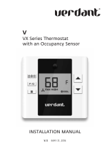
3. Remove the four (4) nuts which secure the discharge air grille
to the cabinet front.
Discharge Air Flow Grille Removal
4. Rotate the grille 180° clockwise.
5. Reinstall the nuts securing the discharge air grille to the cabi-
net front. Reinstall the cabinet front on the unit.
REMOTE THERMOSTAT
To operate this unit with a “manufacturer-approved” remote
thermostat, configure the control to be operated by the remote
thermostat. Enter configuration mode C1 and then select option
Code L5 (see Configuration Settings in back of manual). When
in the remote mode, the unit will only respond to the thermostat
inputs (terminal strip positions GL (or GH), W2, Y/W1, and B*
shown in “Control Board User Inputs” illustration). NOTE: Once
configuration C1 with option code L5 has been selected, the
control touchpad will no longer accept inputs other than configu-
ration and diagnostics modes. The room occupant must operate
the unit at the remote mounted thermostat.
NOTE: In remote mode, the 3-minute compressor time delay, the
random restart feature and the freeze protection feature are all active
(see Unit Features section).
THERMOSTAT LOCATION
This unit is designed to be operated with remote wall mounted
thermostats. For further information on thermostats approved for
use with this unit, contact your sales representative.
For best performance results, the thermostat should be located
approximately five feet above the floor on a vibration free, inside
wall in an area with good air circulation.
Do not install the thermostat where it may be affected by the
following:
Dead spots behind doors, in corners or under cabinets
Hot or cold drafts from air ducts
Radiant heat from the sun, appliances, or fireplaces
Concealed pipes and chimneys
Unheated (uncooled) areas behind the thermostat, such as
an outside walls
Consult the instruction sheet packaged with the thermostat for
further details on mounting and operation.
REMOTE THERMOSTAT OPERATION
Approved thermostats vary slightly in construction and, with few
exceptions, are operated similarly. The following operational
description pertains to approved nonprogrammable thermostats
that energize G in Heat and Cool mode.
HEAT/OFF/COOL Switch
OFF - cooling and heating functions are defeated.
HEAT - the selected room temperature is maintained by cy-
cling either in the heat pump mode or electric strip heat. A
PTH unit is switched from the heat pump mode to electric
strip heat when the coil temperature is 20°F or when the
heat pump cannot keep up with the heating load and a two
stage thermostat is used.
COOL - the selected room temperature is maintained by
cycling the air conditioner.
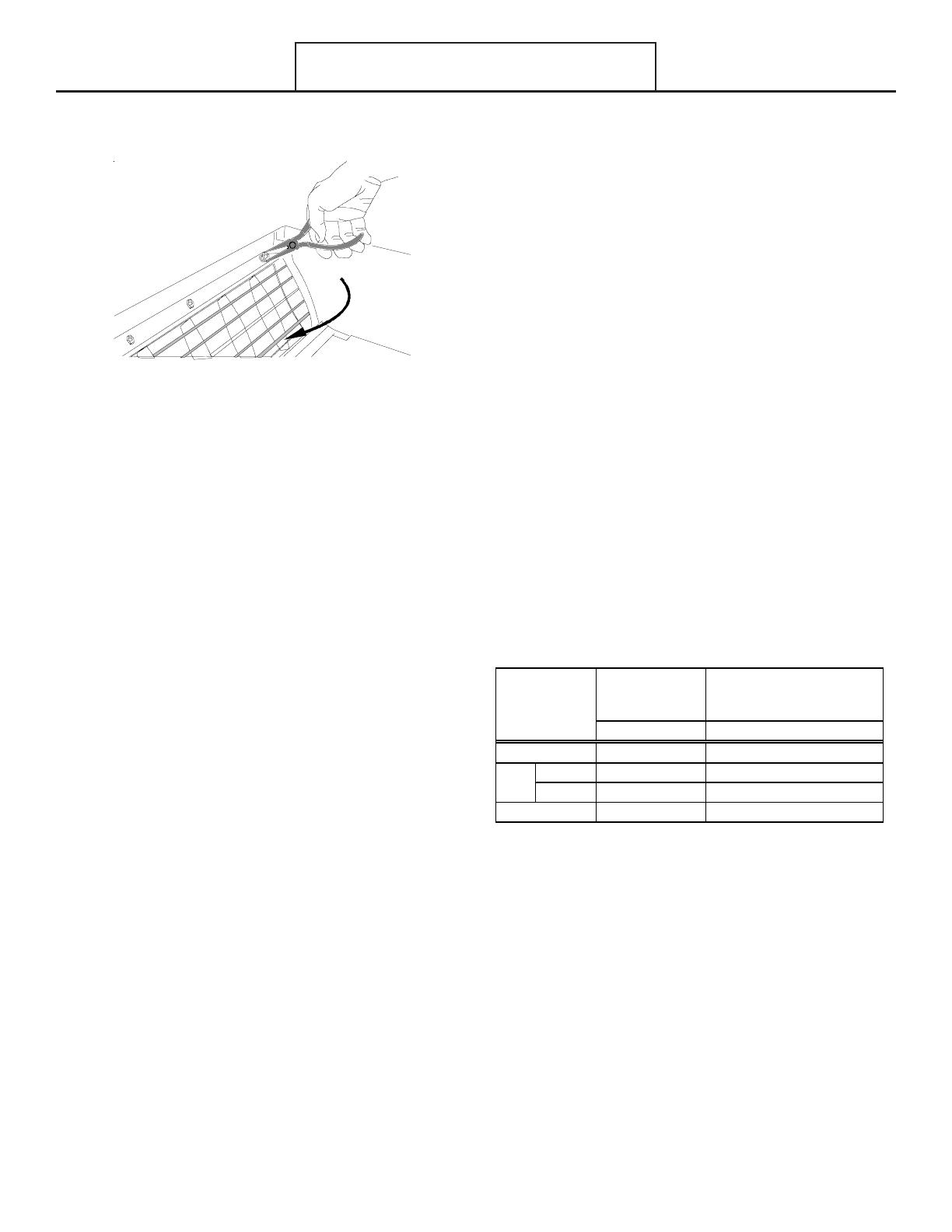
Table 4 summarizes the thermostat input combinations and the
respective unit functions. The following wiring schematic illustra-
tions show wiring schematics for heat pump and straight cool
units with electric resistance heat, respectively.
Heat Pump
Thermostat
Input
Electric Heat
Thermostat
Input
R Terminal to: R Terminal to:
NONE NONE
Stage 1 GL*, Y/W1, B**, O GL* Y/W1, B**, or GL*, W2, O
Stage 2 GL*, W2 n/a
GL*, Y/W1, B**, O GL*, Y/W1
Unit Function
*or GH depending on speed required
**If configured, B and O can be used interchangeably.
OFF
COOL
HEA T
Table 4 - Remote Control Inputs
NOTE: The PTAC Wire Harness Kit (PWHK01C) is required for
remote thermostat options.
ADDITIONAL NOTES:
1. For heat pump operation, a room thermostat with a B** (heat-
ing changeover) terminal is required. This will mean that some
“auto changeover” thermostats cannot be used, as many of
them either do not have a B** terminal, or else energize the
B** terminal continuously when in the “auto” position.
2. Additional wiring should be run for future changeover to Heat
Pump or thermostat options.
Operating Instructions
**If configured, B and O input terminals can be used interchangeably.
13
3. Run 6 to 8 wires during initial installation. Tape or cap off any
unused wires.
DS1 DS2 MS1 MS2 EH IN LS FD1 FD2 TF- TF+ C R GL W2 Y/W1 B GH
REMOTE THERMOSTATAUXILIARY
X1
O
B**
Y
W1
W2
G*
R
Thermostat
Connections
Control Board
Connections
Wiring Schematic for Straight Cool Unit
*NOTE: For high speed fan operation, connect “G” to “GH”.
DS1 DS2 MS1 MS2 EH IN LS FD1 FD2 TF- TF+ C R GL W2 Y/W1 B GH
REMOTE THERMOSTATAUXILIARY
X1
O
B**
Y
W1
W2
G*
R
Thermostat
Connections
Control Board
Connections
Wiring Schematic for Remote Heat Pump
*NOTE: For high speed fan operation, connect “G” to “GH”.
Table 5 shows the maximum wire length and corresponding gage
size for installation of a remote thermostat.
Maximum Wire
Len
g
th
Wire Size
(AWG)
Maximum Length
Allowed
#24 400 ft
#22 600 ft
#20 900 ft
#18 1500 ft
#16 2000 ft
Table 5 - Maximum Wire Length for Remote
Control Connection
WARNING
T
O PREVENT PROPERTY DAMAGE, PERSONAL INJURY OR DEATH DUE TO
ELECTRIC SHOCK, DISCONNECT THE ELECTRICAL POWER SUPPLY BEFORE
CLEANING THIS UNIT.
Operating Instructions
**If configured, B and O input terminals can be used interchangeably.
14
WARNING
T
O AVOID THE RISK OF PROPERTY DAMAGE, ELECTRICAL SHOCK OR
PERSONAL INJURY, CLEAN AIR FILTERS AND COILS REGULARLY.
C
LOGGED
OR SEVERLY RESTRICTED FILTERS OR COILS REDUCE AIRFLOW WHICH CAN
CAUSE DRASTIC EFFICIENCY LOSS AS WELL AS SEVERE COMPONENT DAMAGE
TO COMPRESSORS, ELECTRIC HEATER OR FAN MOTOR.
I
N EXTREME CASES,
CLOGGED FILTERS AND/OR COILS MAY CREATE A FIRE HAZARD AND WILL
VOID THE WARRANTY.
WARNING
S
OME LOCAL CONDITIONS AND ENVIRONMENTS CAN CAUSE FUNGI AND OTHER
MATERIAL TO GROW INSIDE THE
PTAC
UNIT.
T
HIS MATERIAL WHEN DRIED,
AS WELL AS OTHER FOREIGN MATERIAL, SIMILAR TO DRYER LINT IN YOUR
CLOTHES DRYER, ARE FIRE HAZARDS.
B
E SURE TO THOROUGHLY CHECK AND
CLEAN THE UNIT'S COILS, BLOWER WHEEL AND BASEPAN PER THE
INSTRUCTIONS CONTAINED IN THIS MANUAL.
MONTHLY MAINTENANCE AND CLEANING
Intake Air Filter
To properly maintain the operational performance of your PTAC
unit, it is extremely important that the inlet air filter be cleaned
once per month or more often if operated in dusty or dirty
locations or conditions. The intake air filter is constructed of
durable polypropylene. The “air intake” air filter can be easily
inserted into the cabinet front using the cabinet filter guides. The
intake air grille swings out for easy access to the filter. Before
cleaning the intake filter, turn the unit off by setting the mode
switch to the OFF position. Filter should be cleaned as required.
The following procedure is used to remove the intake filter:
1. Open the intake grille by grasping the top intake louver.
2. Pull the intake grille open.
3. Slide filter upward and remove.
4. Clean filter with vacuum or with running water.
Reverse this procedure to reinstall the filter.
NOTE: Available accessory filter kits are FK10B (air intake filter -
10 per pack) and CFK10B
(charcoal filter - 10 per pack). The charcoal filters will greatly
improve the quality of the air by absorbing odors from tobacco
smoke, mold, mildew, etc. Both filters are permanent and
cleanable. Contact your sales person for details.
`
Intake Filter Removal
Vent Screen
Before cleaning the vent screen, disconnect power to the unit by
unplugging the power cord at the wall outlet or subbase, or
disconnect power at the fuse box or circuit breaker. If unit is
operated with vent door closed, the vent screen does not need
to be cleaned.
1. Remove the cabinet front as described in Front Removal.
2. Remove the six screws securing the chassis to the wall
sleeve.
3. Slide the chassis out of the wall sleeve far enough so that the
vent screen is accessible.
4. Remove the three screws securing the vent mesh screen to
the partition panel.
5. Clean and replace the vent screen, slide the chassis back into
the wall sleeve, secure it in place with six screws and reinstall
the front cabinet.
Vent - (Left Side Unit)
Maintenance and Cleaning
15
Cabinet Front
The cabinet front and discharge air grille can be cleaned with a
water dampened cloth . Under no circumstances should hydro-
carbon-based cleaners (e.g. acetone, benzene, naphtha gaso-
line, etc.) be used to clean the front or air grilles. Use care when
cleaning the control area.
YEARLY MAINTENANCE AND CLEANING
NOTE: Use a mild biodegradable detergent such as Simple
Green when cleaning the unit. Special care must be taken to
protect the unit’s control board and other electrical components
from getting any water on them while cleaning. The use of harsh
or caustic cleaning agents or materials such as bleach or coil
cleaners that are not designed for PTAC products will cause
damage or deterioration of the aluminum fin or coil material and
is not recommended. Care must be taken not to bend the
aluminum fin stock.
Routine Scheduled Maintenance
To achieve continuing top performance and high efficiency,
establish a “once a year” cleaning/inspection schedule for the
unit. Take the unit out of the sleeve and thoroughly clean and
rinse. Be sure to include in the yearly cleaning the evaporator
coils, and condenser coils, basepan, and drain passages.
Scheduled maintenance can be accomplished by either local
maintenance staff or by an authorized servicer. They must follow
the instructions described in this manual.
Adverse Operating Conditions Maintenance
Units operating in dusty or corrosive locations; i.e. dusty con-
struction site or sea coast, must be cleaned more often. A
minimum of four (4) times a year will maintain proper operational
conditions and protect unit components.
Wall Sleeve
Clean the wall sleeve while cleaning the unit. The caulking
around the sleeve should be checked to make sure that any
potential air and water openings around the sleeve are properly
sealed. The wall sleeve’s level should also be rechecked.
Proper leveling for most installations are a ¼ bubble tilt to the
outside and level from right to left. Contact your sales person for
detailed maintenance or cleaning instructions.
Basepan and Condenser Coil
CAUTION
D
O NOT USE COMMERCIAL GRADE COIL CLEANERS.
S
OME OF THESE
CLEANERS MAY CONTAIN
E
THYLENE
D
IAMINE
T
ETRACETIC
A
CID (
EDTA
)
WHICH CAN SHORTEN THE LIFE OF THE CONDENSER COIL.
Before cleaning the basepan and condenser coil, turn OFF unit
mode switch and disconnect power to the unit. To disconnect
power, either unplug the power cord at the wall outlet or subbase,
or disconnect power at the fuse box or circuit breaker.
1. Create a water-tight seal by tightly covering the entire control
panel area and fan motor with plastic. Creating this seal pre-
vents water from entering the control area or the fan motor
and damaging the unit.
2. Spray condenser coil and basepan down with water. Next
spray a mild biodegradable detergent such as Simple
Green onto the condenser coil and basepan. Let set for
five (5) minutes.
3. Rinse condenser coil and basepan with water again. NOTE:
Ensure water pressure is no higher than that of an ordinary
garden hose and the water temperature no higher than 120°F.
4. Tilt the non-compressor side of the unit up no higher than 45
degrees and allow water to drain out the other side of the unit.
5. Remove excess water left in the basepan by wiping the
basepan with a dry cloth.
6. Remove the water-tight seal from the motor and control panel
area.
7. Reinstall unit back into wall sleeve.
8. Allow unit to dry for 24 hours before reapplying power. When
power is reapplied test unit for proper operation.
9. Place a non-acidic algaecide in the basepan to inhibit bacteria
growth. Ensure the algaecide is compatible with wet coil op-
eration and is not corrosive to the coil.
CAUTION
H
IGH PRESSURE AND HIGH TEMPERATURE CLEANING IS NOT RECOMMENDED.
D
OING SO COULD DAMAGE THE ALUMINUM FIN STOCK AND ELECTRICAL
COMPONENTS.
Clearance Check
Clearances around the unit should also be checked to make sure
that the intake air and discharge air paths have not become
blocked or restricted. A minimum of eight inches clearance is
needed from unit to furniture , beds, or other objects for proper
operation. Restricted discharge or intake air will reduce the unit’s
operational performance. In severe airflow restrictions damage
can occur to unit components such as the compressor, electric
heater or fan motor.
Maintenance and Cleaning
16
Normal Operating Sounds and Conditions
Water trickling sounds
Water is picked up and distributed over the coil. This improves the efficiency and
helps with water removal.
Water dripping
Water will collect in the base pan during high humidity days. This can cause
overflow and drip from the outside of the unit.
Air sounds
The fan cycle switch sets the operational mode of the fan in the ON position. The
fan will run continuously whenever power is applied in this mode. In the AUTO
position, the fan will cycle on and off with the compressor or electric heater.
Starting delay
You may notice a few minutes delay in the starting if you try to restart the unit too soon
after turning it off or if you adjust the thermostat right after the compressor has shut off.
This is due to a built in delay to protect the compressor.
Obtaining Service
In the event this unit requires repair or servicing beyond what is covered in this manual, contact an authorized service organization.
To obtain an authorized servicer, contact your sales representative or agency.
17
The control can be configured to operate a wide range of options. The options listed below with the * are the factory default settings.
If these are acceptable, then the unit does not require any additional configuration and is fully operable. To configure the unit, first
select the configuration feature code setting and then an option code to change from the factory default setting.
To enter configuration feature mode:
1. Press and continue to hold the up and down
arrow keys and quickly press the OFF key twice within a two (2) sec-
ond time frame. The display will alternate between displaying the feature code C1 and the option code 0 (factory default set-
ting)
. The lower right dot on the display will flash. To enter the other option codes for C1 (rE and L5) press either the up or down
arrow key.
To select a configuration feature code other than C1, press the HEAT
key until the desired configuration comes up. To
scroll to a previously viewed configuration codes press the COOL key.
Once you have scrolled to the correct feature, then to select the option code for your desired configuration, press either the up or
down key
to scroll through the options of the selected feature code.
To exit configuration mode:
1. Press the OFF
key. Configuration feature mode will also exit if no keys are pressed for a period of two (2) minutes.
Below are the most common configuration settings. Additional codes are present and may be accessed within this menu. Contact the
manufacturer for additional information.
Configuration Settings
Interface Usage 0* Unit is only controlled by the touchpad behind the door.
rE
Unit is both controlled by a wireless thermostat
and/or the touchpad behind the door.
L5
Unit is controlled by a wired thermostat only via
on the low voltage terminals.
Au* The fan only runs with the call for heating or cooling.
On The fan runs continuously except in the OFF position.
C4 Room Indentification first two
digits (00 to 99) 00-99 Set first two digits of room identification
C5 Room Identification last two
digits (00 to 99) 00-99 Set last two digits of room identification
0* "No Occupancy" detection devices
1 Wired Door Switch and Motion Sensor present
18
Enter "No Occupancy" routine 18 hours after last control
selection
1 Normally Closed Device
0* Normally Open Device
C8 Cooling Temperature Limiting
60-72 (65*)
Select temperature between 60 and 72 for minimum
cooling set point
C9 Heating Temperature Limiting
74-90 (80*)
Select temperature between 74 and 90 for maximum
heating set point
8* Mating thermostat has a "B" terminal
0 Mating thermostat has an "O" terminal
c1
Not used
0* Not Active
AActive
c3 Unrented Cooling Temperature
60-90 (79*) Select temperature between 60 and 90 unrented cooling set point
c4 Unrented Heating Temperature
60-90 (63*) Select temperature between 60 and 90 unrented heating set poin
t
0* Not Twinned
5 Twinned (Slave)
0* Not Active
1Active
U Active in No occupancy / Unrented State
CC Dehumidistat call for a drop in temperatur
e
3-8 3-8
F* Fahrenheit Scale
C Celsius Scale
1* On
0Off
* Indicates factory default.
Cd English/Metric Temperature
CE Freeze Protection
CA Twinned Unit
DehumidificationCb
Wired Unrented Set Backc2
Option
Code
Fea tur e
Code
Description
C6 Occupancy
C7 Motion Sensor Type
C0 Reverse Cycle "B" or "O"
selection for thermostat
Description
C1
C2 Fan Operation
18
The Diagnostic Maintenance & Status Report provides detailed information on PTAC control operation and operational status includ-
ing present modes, failures, airflow restriction warnings, operating temperatures, and past failures. The lower right hand dot on the
center display flashes in this mode. In some cases the green LED located in the lower left hand corner of the touchpad below the OFF
key will also be lit. This Green LED “Status Light“ only illuminates if there is an status code that has been activated and should be
reviewed. In most cases, this light indicates that the indoor room filter is dirty should be cleaned or replaced. NOTE: Dirty filters
cause the unit to consume more energy than normally needed to condition a room. Once the filter has been cleaned or replaced, the
LED should go out. If the LED is still illuminated after the filter has been cleaned, activate the Diagnostic and Status mode to view
any active codes. The unit may need additional cleaning or maintenance of the evaporator or condenser coils. Please perform this
step before calling a servicer. A servicer should be called only if cleaning the filter or coils does not clear the status code or
the code indicates that servicer should be called.
DIAGNOSTIC STATUS REPORT MODE.
To enter Diagnostic Status Report mode, press and hold the up and down arrows and, while holding, quickly press the
COOL key
twice.
ACTIVE FAILURES.
If there are no active failures or lockouts, the display will show a double dash, “- -”. If there is a code listed, see the unit “Diag-
nostic Codes” chart for a list of definitions.
OPERATING TEMPERATURES.
If not in Diagnostic Status Report Mode, enter as instructed above and press the Fan Speed key.
If already in Diagnostic Status Report mode, press the Fan Speed key. The display will show the temperature of the de-
sired set point, SP; the temperature at the wireless thermostat, rL; the indoor ambient temperature behind the filter, IA; the indoor
coil temperature, IC; the indoor discharge air temperature, Id; the outdoor coil temperature, OC; the outdoor ambient tempera-
ture, OA; and the spare probe temperature, IH. If any of the probes are not populated the display will show the corresponding
failure code.
PAST FAILURE LOG
If not in Diagnostic Status Report Mode, enter as instructed above and press the Fan Speed key twice.
If already in Diagnostic Status Report mode, press the Fan Speed
key. While the display is showing operating tempera-
tures, the last 10 failure codes active or past can be requested by pressing the Fan Speed key again. The codes are dis-
played last entry first followed subsequently by each preceding code.
Note that modes F1 and Fd are also displayed in the normal control operation (see “Diagnostic Codes” chart).
To exit Diagnostic Status Report mode, press the OFF key.
Diagnostic Maintenance & Status Report
19
STATUS DISPLAY
ERROR
LIGHT
SUGGESTED ACTION
FP
Freeze
Protection
Engaged. The room temperature
measured by the wireless remote thermostat or indoor
ambient thermistor active sensor falls below 40°F.
YN
No Action required. This setting will disengage
when the room temperature rises above 43°F.
Fd
Front
Desk
switch is closed. All outputs are switched off. Y N
Open front desk switch to allow occupant unit
operation.
Fb
Low Remote Battery Warning. N Y Replace Battery in Wireless Devices.
Indoor Ambient Thermistor reads outside the range -20°F
to 200°F
&
the wireless thermostat is not communicating
to the unit control or
Indoor Ambient Thermistor (IAT) without a wireless remote
thermostat reads outside the range -20°F to 200°F.
F4
Indoor Coil Thermistor either above or below operating
tolerances.
N Y Replace Red Indoor Coil Thremistor .
F5
Wireless Thermostat failure. N Y Replace Wireless Thermostat.
F6
Indoor Discharge Thermistor either above or below
operating tolerances.
NY
Replace Yellow Indoor
Discharge Thermistor.
L6
Discharge Air Too Hot.. N Y Clean Filter or Remove Air Blockage.
L8
Air Restriction in Heating. N Y Clean Filter or Evaporator Coil.
L9
Air Restriction in Cooling. N Y Clean Filter or Evaporator Coil.
LC
Outdoor Coil Thermistor temperature high. N Y
Clean Condensor Coils, Check Fan
fault code. Code will reset after cleaning.
C1
Clean Indoor Coil / Filter. N Y Check for Blocked Indoor Air.
C0
Clean Outdoor Coil. N Y Check for Blocked Outdoor Air.
CODE
M
O
D
E
S
A
I
R
F
L
O
W
W
A
R
N
I
N
G
S
Replace black Indoor Ambient Thermistor or
Wireless Remote Thermostat.
YY
F
A
I
L
U
R
E
S
F1
Diagnostic Codes
20
  • Page 1 1
  • Page 2 2
  • Page 3 3
  • Page 4 4
  • Page 5 5
  • Page 6 6
  • Page 7 7
  • Page 8 8
  • Page 9 9
  • Page 10 10
  • Page 11 11
  • Page 12 12
  • Page 13 13
  • Page 14 14
  • Page 15 15
  • Page 16 16
  • Page 17 17
  • Page 18 18
  • Page 19 19
  • Page 20 20

Amana DigiSmart PTC074E25AXXX Owner's manual

Category
Heat pumps
Type
Owner's manual

Ask a question and I''ll find the answer in the document

Finding information in a document is now easier with AI