
INTEGRATED REFRIGERATION
INSTALLATION INSTRUCTIONS
INSTRUCCIONES DE INSTALACIÓN
INSTRUCTIONS D’INSTALLATION
ISTRUZIONI PER L’INSTALLAZIONE
INSTALLATIONSANWEISUNGEN
Page is loading ...
Page is loading ...

SUB-ZERO
®
is a registered trademark of Sub-Zero, Inc.
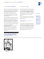
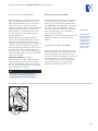
As you follow these instruc tions, you will
notice WARNING and CAUTION symbols.
This blocked information is impor tant for the
safe and efficient installation of Sub-Zero
equipment. There are two types of potential
hazards that may occur during installation.
Another footnote we would like to identify is
IMPORTANT NOTE: This highlights informa-
tion that is especially relevant to a problem-
free installation.
signals a situation where minor injury or
product damage may occur if you do not
follow instructions.
states a hazard that may cause serious
injury or death if precautions are not
followed.
CONTENTS
Installation Recommendations 5
Installation Specifications 6
Installation Instructions 9
Installation Checklist 22
Service Information 23
Features and specifications indicated herein and
on the website are subject to change at any time
without notice. Check our website, subzero.com,
for the most up-to-date specifications.

5
TOOLS AND MATERIALS REQUIRED
The following is a list of tools and materials
that should be available for proper installation.
Phillips screwdriver set
Slotted screwdriver set
1.2 m of 6,35 mm copper tubing and saddle
valve for the water line—part #4200880
(do not use self-piercing valves)
Copper tubing cutter
Level—.6 m and 1.2 m recommended
Appliance dolly able to support 227 kg
and adequate help to handle the weight of
the unit
Various sized pliers
Wrench set
Allen wrench set
11 mm hex bolt nut driver
Crescent wrenches
Drill and assorted drill bits
Masonite, plywood, 3,175 mm pressed
fiberboard, cardboard or other suitable
material to protect finished flooring
Appropriate materials to cover and protect
the home and its furnishings during
installation
INSTALLATION
RECOMMENDATIONS
The importance of the installation of the
Sub-Zero Integrated unit cannot be overem-
phasized. Installation should be done by a
qualified installer.
Before you begin the installation process,
it is recommended that you read this entire
Installation Instructions book. There are key
details that you should take special care to
observe during the installation. By reading
these instructions carefully, you will make the
installation process easier, problem-free and,
most importantly, safe.
Any questions or problems about the
installation should be directed to your
Sub-Zero dealer. You can also visit our website
at subzero.com.
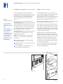
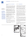
SITE PREPARATION
Make sure that the finished rough opening
where the Integrated unit is to be installed is
properly prepared. Refer to the Overall
Dimensions and Installation illustrations for
your specific model on the following pages.
Make sure that the rough opening dimensions,
door and drawer clearances, electrical service
and plumbing are correct for the model you
are about to install.
Be sure that the plumber, electrician and
cabinet installer have this information before
finishing work is completed.
IMPORTANT NOTE:
The inside edges of the
rough opening, as well as the sides and a
portion of the backside of the decorative
panels will need to be finished, as they will be
exposed when the doors are open.
INTEGRATED INSTALLATION RECOMMENDATIONS

6
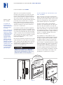
INTEGRATED INSTALLATION SPECIFICATIONS
TOP OF
ROUGH
OPENING
1995
mm*
876
mm*
356 mm
21
mm
248
mm
102
mm
2032
mm*
686
mm
610
mm
*
13 mm
+
_
ADJUSTMENT IN LEVELING LEGS
FRONT VIEW SIDE VIEW
(UNIT DIMENSION) (UNIT DIMENSION)
10
mm
337
mm
13
mm
260
mm
518
mm
DOOR
MOUNTING
DETAIL
DRAWER
MOUNTING DETAIL
105˚
90˚
90˚ DOOR OPENING
DOOR/DRAWER
CLOSED
MAXIMUM DOOR OPENING
*
DOOR/DRAWER PANEL THICKNESS NOT INCLUDED – DIMENSION WILL VARY WITH INSTALLATION
DOOR/DRAWER
CLOSED
495
mm*
648
mm*
610 mm
657 mm
117 mm*
TOP VIEW
635
mm
686
mm
2032
mm
686
mm
635
mm
ANTI-TIP
BRACKET*
WATER LINE
BOTTOM ENTRY
LOCATION
WATER LINE
SIDE ENTRY
LOCATIONS
38
mm
38 mm
686
mm
38 mm
394 mm
229
mm
343 mm 343 mm
ANTI-TIP
BRACKET
152
mm
TOP VIEW TOP VIEW
SIDE VIEWFRONT VIEW
WATER LINE
SIDE ENTRY
LOCATION
ANTI-TIP
BRACKET
NOTE: ANTI-TIP BRACKET MUST BE INSTALLED TO
PREVENT UNIT FROM TIPPING FORWARD
114
mm
64 mm
394 mm
19
mm
76
mm
6
mm
330 mm 229 mm
ANTI-TIP
BRACKET
LOCATE WATER LINE
(REAR ENTRY) WITHIN
SHADED AREA
LOCATE ELECTRICAL WITHIN
SHADED AREA
*PLACEMENT OF THE
ANTI-TIP BRACKET
SHOULD BE 610 mm
FROM THE FRONT OF THE
UNIT WITHOUT PANELS
TO THE BACK OF THE
ANTI-TIP BRACKET.
E
W
E
W
W
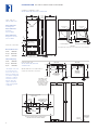
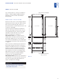
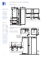
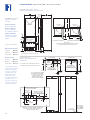
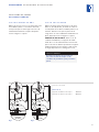
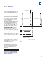
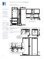
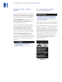
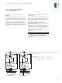
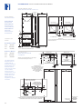
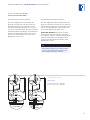
INSTALLATION
Models ICB700TR, ICB700TFI
and ICB700TCI
Models without an ice maker will not
require the water line connection.
OVERALL DIMENSIONS
Models ICB700TR, ICB700TFI and ICB700TCI
TALL UNITS
686 mm Wide Units
Model ICB700TR
All Refrigerator
Model ICB700TFI
All Freezer
with Ice Maker
Model ICB700TCI
Refrigerator | Freezer
with Ice Maker
SPECIFICATIONS
Overall Dimensions
Width 686 mm
Height 2032 mm
Depth 610 mm
Finished Opening
Width 686 mm
Height 2032 mm
Depth 635 mm*
*The depth of the unit
is 610 mm from the
front of the unit to its
back. Your design may
necessitate moving the
unit back or cabinets
forward to achieve a
flush fit. This will
require a minimum
rough opening depth
of 635 mm.

7
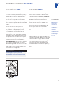
INTEGRATED INSTALLATION SPECIFICATIONS
DOOR MOUNTING
DETAIL
DRAWER MOUNTING
DETAIL
TOP OF
ROUGH
OPENING
1976
mm*
876
mm*
10
mm
337
mm
13
mm
260
mm
518
mm
356 mm
33
mm
248
mm
102
mm
2032
mm*
914
mm
610
mm
FRONT VIEW SIDE VIEW
(UNIT DIMENSION) (UNIT DIMENSION)
*
13 mm
+
_
ADJUSTMENT IN LEVELING LEGS
105˚
90˚
90˚ DOOR OPENING
DOOR/DRAWER
CLOSED
MAXIMUM DOOR OPENING
DOOR/DRAWER
CLOSED
495
mm*876
mm*
610 mm
886 mm
178
mm*
*
DOOR/DRAWER PANEL THICKNESS NOT INCLUDED – DIMENSION WILL VARY WITH INSTALLATION
TOP VIEW
ANTI-TIP
BRACKET*
*PLACEMENT OF THE
ANTI-TIP BRACKET
SHOULD BE 610 mm
FROM THE FRONT OF THE
UNIT WITHOUT PANELS
TO THE BACK OF THE
ANTI-TIP BRACKET.
635
mm
914
mm
2032
mm
686
mm
635
mm
WATER LINE
BOTTOM ENTRY
LOCATION
WATER LINE
SIDE ENTRY
LOCATIONS
38
mm
38 mm
686
mm
38 mm
508 mm
343
mm
457 mm
ANTI-TIP
BRACKET
457 mm
152
mm
TOP VIEW TOP VIEW
SIDE VIEW FRONT VIEW
WATER LINE
SIDE ENTRY
LOCATION
ANTI-TIP
BRACKET
64 mm
508 mm
19
mm
76
mm
445 mm 343 mm
ANTI-TIP
BRACKET
NOTE: ANTI-TIP BRACKET MUST BE INSTALLED TO
PREVENT UNIT FROM TIPPING FORWARD
114
mm
6
mm
LOCATE WATER LINE
(REAR ENTRY) WITHIN
SHADED AREA
LOCATE ELECTRICAL WITHIN
SHADED AREA
E
W
E
W
W
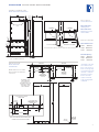
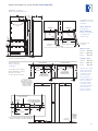
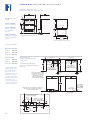
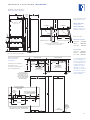
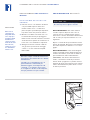
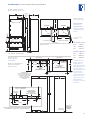
INSTALLATION
Models ICB736TR
and ICB736TCI
Models without an ice maker
will not require the water line
connection.
OVERALL DIMENSIONS
Models ICB736TR and ICB736TCI
TALL UNITS
914 mm Wide Units
Model ICB736TR
All Refrigerator
Model ICB736TCI
Refrigerator | Freezer
with Ice Maker
SPECIFICATIONS
Overall Dimensions
Width 914 mm
Height 2032 mm
Depth 610 mm
Finished Opening
Width 914 mm
Height 2032 mm
Depth 635 mm*
*The depth of the unit
is 610 mm from the
front of the unit to its
back. Your design may
necessitate moving the
unit back or cabinets
forward to achieve a
flush fit. This will
require a minimum
rough opening depth
of 635 mm.

8
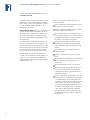
INTEGRATED INSTALLATION SPECIFICATIONS
DRAWER
MOUNTING DETAIL
876
mm*
248
mm
102
mm
FRONT VIEW SIDE VIEW
10
mm
337
mm
13
mm
260
mm
518
mm
686
mm
610
mm
(UNIT DIMENSION) (UNIT DIMENSION)
*
13 mm
+
_
ADJUSTMENT IN LEVELING LEGS
*
DRAWER PANEL THICKNESS NOT INCLUDED
DRAWER CLOSED
495
mm*
610
mm
657 mm
TOP VIEW
ANTI-TIP
BRACKET*
*PLACEMENT OF THE
ANTI-TIP BRACKET
SHOULD BE 610 mm
FROM THE FRONT OF THE
UNIT WITHOUT PANELS
TO THE BACK OF THE
ANTI-TIP BRACKET.
635
mm
686
mm
876
mm
686
mm
635
mm
WATER LINE
BOTTOM ENTRY
LOCATION
WATER LINE
SIDE ENTRY
LOCATIONS
38
mm
38 mm
686
mm
38 mm
394 mm
229
mm
343 mm 343 mm
ANTI-TIP
BRACKET
152
mm
TOP VIEW TOP VIEW
SIDE VIEW FRONT VIEW
WATER LINE
SIDE ENTRY
LOCATION
ANTI-TIP
BRACKET
NOTE: ANTI-TIP BRACKET MUST BE INSTALLED TO
PREVENT UNIT FROM TIPPING FORWARD
114
mm
64 mm
394 mm
19
mm
76
mm
6
mm
330 mm 229 mm
ANTI-TIP
BRACKET
LOCATE WATER LINE
(REAR ENTRY) WITHIN
SHADED AREA
LOCATE ELECTRICAL WITHIN
SHADED AREA
E
W
E
W
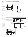
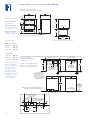
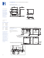
W
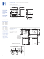
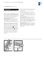
INSTALLATION
Models ICB700BR, ICB700BFI
and ICB700BCI
Models without an ice maker
will not require the water line
connection.
OVERALL DIMENSIONS
Models ICB700BR, ICB700BFI and ICB700BCI
BASE UNITS
Model ICB700BR
All Refrigerator
Model ICB700BFI
All Freezer
with Ice Maker
Model ICB700BCI
Refrigerator | Freezer
with Ice Maker
SPECIFICATIONS
Overall Dimensions
Width 686 mm
Height 876 mm
Depth 610 mm
Finished Opening
Width 686 mm
Height 876 mm
Depth 635 mm*
*The depth of the unit
is 610 mm from the
front of the unit to its
back. Your design may
necessitate moving the
unit back or cabinets
forward to achieve a
flush fit. This will
require a minimum
rough opening depth
of 635 mm.

9
INTEGRATED INSTALLATION INSTRUCTIONS
ELECTRICAL REQUIREMENTS
A 220-240 V AC, 50/60 Hz, 10 amp circuit
breaker and electrical supply are required. A
separate service, servicing only this appliance,
is required.
All Integrated models are equipped with a
power supply cord with a 3-prong grounding
plug, which must be plugged into a mating
3-prong ground ing-type wall recep tacle. Follow
all local codes and ordinances when installing
the receptacle. For location of the electrical
supply, refer to the Installation illustration for
your unit on pages 6–8.
IMPORTANT NOTE:
A ground fault circuit
interrupter (GFCI) is not recommended and
may cause interruption of operation.
IMPORTANT NOTE:
The Integrated line is
equipped with an appliance inlet type device.
This allows easy replacement of the power
cord. The appliance inlet is located on top of
the unit on the compressor shroud. When
replacing the power cord make sure that the
replacement cord is rated HO5VV-F3G1.0 or
equivalent to ensure safe operation of the
appliance.
Do not use an extension cord or two-
prong adapter. Electrical ground is
required on this appliance. Do not remove
the power supply cord ground prong.
The outlet must be checked by a qualified
electrician to be sure that it is wired with
the correct polarity. Verify that the outlet
provides 220-240 V AC and is properly
grounded.
Always shut power off at the circuit
breaker before performing any installa-
tion, service or maintenance.

10
INTEGRATED INSTALLATION SPECIFICATIONS
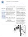
PLUMBING REQUIREMENTS
For Integrated models with an automatic ice
maker, rough in the water supply line. Connect
the 6,35 mm water line from the ice maker
water valve to the copper water supply. Use an
easily accessible shut-off valve between the
water supply and the unit. This shut-off valve
should not be installed behind the unit. Do not
use self-piercing valves. A saddle valve kit
(part #4200880) is avail able from your Sub-
Zero dealer.
The Installation illustrations on pages 6–8
show the precise placement of the water line.
When routing through the side walls, you must
place the water line within 13 mm of the floor
and as close as possible to the back wall.
The line must be routed around the anti-tip
bracket so it clears the bracket and the leveling
feet of the unit. Refer to the top view in the
Installation illustration for your unit on pages
6–8. Regardless of the routing, allow for 686
mm of excess water line to remain outside the
wall or floor for easy connection to the unit.
IMPORTANT NOTE:
Do not route the water
supply line in front of the compressor tray.
The tray must be slid forward for service.
A line filter is required when water conditions
have a high sediment content. The ice maker
operates on water pressure of 1.4 bar to
6.9 bar.
A reverse osmosis system can be used,
provided there is a consistent water pressure
of 1.4 bar to 6.9 bar supplied to the water valve
at all times.
IMPORTANT NOTE:
In some cases a reverse
osmosis water filter system may not be able
to maintain the minimum water pressure
consistently.
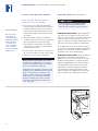
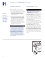
ACCESSORIES
Optional acces-
sories are available
through your
Sub-Zero dealer. To
obtain local dealer
information, visit
our website,
subzero.com.

11
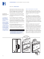
INTEGRATED INSTALLATION INSTRUCTIONS
PANEL CONSIDERATIONS
DOOR AND DRAWER PANELS
To install door and drawer panels, refer to the
instructions under Panel Installation on page
18. You should check panel dimensions and
placement before proceeding with installation
of the Integrated unit. If you have questions,
contact your Sub-Zero dealer or cabinet
supplier. Instructions regarding sizing of the
panels are provided in the Sub-Zero Design
Guide.
IMPORTANT NOTE:
A portion of the backside
of the decorative panels will need to be
finished, as they will be exposed when the
doors are open.
SIDE PANELS
Side panels for integrated models are not
attached to the unit. You must securely fasten
the panels to adjacent cabinets and floor.
Panels should be fastened to the floor and
walls using ’L’ brackets (hardware not
provided). To help you move the unit into
place, rout out an area in the floor so the ’L’
bracket will sit flush with the floor level.
Brackets and screws are provided for
mounting the unit to adjoining cabinets and
side panels. On the tall units, there are four
side mounting clips on each side and on the
base units, there are two per side. Side panels
must be a minimum of 19 mm thick.
IMPORTANT NOTE:
For installations where
you are not attaching to a side wall or you are
installing two Integrated units together, you
must remove the clips before moving the unit
into place. After removing the clips, replace
the screws in the holes and discard the clips.
Optional components are necessary for
anchoring two Integrated units together. Refer
to Dual Installations on page 21. Optional
components are available through your
Sub-Zero dealer. To obtain local dealer infor-
mation, visit our website, subzero.com.
PANEL
DESIGN
Additional panel
design information
can be found in
the Sub-Zero
Design Guide.
Check our website
at subzero.com.

12
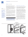
UNPACKING AND MOVING
Uncrate the unit, remove its wood base and
discard the shipping bolts that hold the wood
base to the bottom of the unit. Remove all
packing materials and tape.
IMPORTANT NOTE:
Do not discard the
kickplate/grille, anti-tip bracket and hardware.
These items will be needed for the installation.
Retract the front leveling legs to allow you to
move the unit more easily during installation.
You will extend the leveling legs when the unit
is in its final position to reduce the possibility
of the unit tipping forward.
Use an appliance dolly to move the Integrated
unit. Position the dolly at the side of the unit to
prevent damage to finished surfaces. Secure
the door and/or drawers so they do not open
while moving the unit.
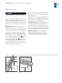
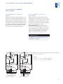
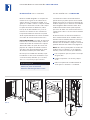
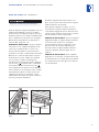
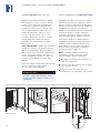
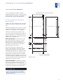
ANTI-TIP BRACKET
INSTALLATION
An anti-tip bracket and hardware is provided
with the Integrated unit. The anti-tip bracket
must be installed on a solid base.
If you are installing the unit in a space deeper
than 610 mm, be sure to locate the anti-tip
bracket so that it engages the unit properly. It
is important that the anti-tip bracket is placed
610 mm from the front of the unit without
panels, to the the back of the anti-tip bracket.
Refer to illustrations 1 and 2 below and note
that for 686 mm wide units dimension A is 343
mm, and 457 mm for 914 mm wide units.
INTEGRATED INSTALLATION INSTRUCTIONS
To prevent the unit from tipping forward
and provide a stable installation, the unit
must be secured in place with the anti-tip
blocking bracket.
Before moving the Integrated unit into
position, protect any finished flooring
with appropriate materials.

13
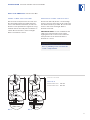
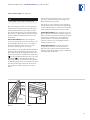
ANTI-TIP BRACKET
INSTALLATION
WOOD FLOOR APPLICATIONS
Use the six #12 x 63,5 mm wood screws and
the six #12 flat washers provided. Drill pilot
holes 5 mm diameter maximum, and be sure
that the screws penetrate through the flooring
material and into the wall plate a minimum of
19 mm. Be sure that the screws hold tight.
Refer to illustration 1 below.
CONCRETE FLOOR APPLICATIONS
Use the two #10 x 95,25 mm concrete wedge
anchors, two #12 x 63,5 mm wood screws and
two #12 flat washers provided. Be sure that the
anchors and screws hold tight. Refer to
illustration 2 below.
IMPORTANT NOTE:
In some installations the
subflooring or finished floor may require
angling the wood screws used to fasten the
anti-tip bracket to the back wall. Refer to
illustrations 1 and 2.
INTEGRATED INSTALLATION INSTRUCTIONS
Make sure that there are no electrical
wires or plumbing in the area which the
screws could penetrate.
WOOD FLOOR
Finished Flooring
Underlayment
Subflooring
Wall Plate
Finished Flooring
Underlayment
Subflooring
Wall Plate
CONCRETE
FLOOR
38
mm
min
Illus. 1 Illus. 2
SPECIFICATIONS
Dimension A
686 mm Wide Units 343 mm
914 mm Wide Units 457 mm

14
ANTI-TIP
BLOCKING BRACKET
INSTALL CONCRETE WEDGE ANCHORS
1)
Drill a 10 mm diameter hole any depth
exceeding the minimum embedment. Clean
the hole or continue drilling additional
depth to accommodate drill fines. Use a
carbide drill bit.
2)
Assemble the washer and nut flush with the
end of anchor to protect threads. Drive the
anchor through the material to be fastened
until the washer is flush with the surface
material.
3)
Expand the anchor by tightening the nut
3–5 turns past hand-tight position or to 25
foot-pounds (34N) of torque.
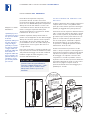
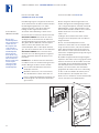
POSITION THE UNIT
IMPORTANT NOTE:
On base units, the top
drawer has a control cable that needs to be
disconnected before removing this drawer.
Refer to illustration 3 below for placement and
how to disconnect this fitting.
The drawers should be placed aside until you
are ready for installation of the panels.
Remove the decorative top and side molding
pieces and the kickplate/grille.
IMPORTANT NOTE:
If two Integrated units are
installed closer than 51 mm to one another, it
is necessary to use the Sub-Zero dual installa-
tion heater kit (ICBTTDUAL). Refer to Dual
Installations on page 21 for additional informa-
tion. The heater plate from this kit must be
attached to the left side exterior of the right
hand unit before the units are slid into
position.
INTEGRATED INSTALLATION INSTRUCTIONS
Always wear safety glasses and use other
necessary protective devices or apparel
when installing or working with anchors.
Anchors are not recommended for use in
lightweight masonry material such as
block or brick, or for use in new concrete
which has not had sufficient time to cure.
The use of core drills is not recommended
to drill holes for the anchors.
Illus. 3
Before moving the Integrated unit into
position, secure the door closed and
remove the drawers.
ACCESSORIES
Optional acces-
sories are available
through your
Sub-Zero dealer. To
obtain local dealer
information, visit
our website,
subzero.com.

15
Pre-level the unit before moving into position.
This is to allow the unit to engage the anti-tip
bracket properly.
Slide the unit into position, making sure the
anti-tip bracket is engaged properly. Screw the
front leveling legs out approximately 5 mm to
make any future adjustments easier.
IMPORTANT NOTE:
When the Integrated unit
is installed, the anti-tip bracket will be posi-
tioned just below the engaging bracket on the
unit. It is not necessary to raise the unit up so
that it locks into the anti-tip bracket, but the unit
must be in alignment with the anti-tip bracket.
IMPORTANT NOTE:
The floor under the
Integrated unit must be at the same level as
the surrounding finished floor to allow the
compressor tray to be slid forward for service.
Illus. 4 Illus. 5
INTEGRATED INSTALLATION INSTRUCTIONS
Unit
On/Off
Unit
On/Off
Shut off the power to the electrical outlet.
POSITION THE UNIT
Before moving the Integrated unit into position,
tape down the water supply line for the ice
maker so it will stay in place as you move the
unit. Refer to the Installation illustration for your
unit on pages 6–8 for placement of the water
line.
IMPORTANT NOTE:
If for any reason the
Integrated unit has been laid on its back or side,
you must allow the unit to stand upright for a
minimum of 24 hours before connecting power.
Plug the power supply cord into the 10 amp
grounded electrical outlet. With power applied
to the appliance, check for lighting and cooling
before going any further. Press the key pad
on the control panel. Refer to illustration 4
below for the location of the key pad for
base units and illustration 5 for tall units. Once
you are satisfied that the unit is operating
properly, shut off power to the electrical outlet
at the circuit breaker and proceed.

16
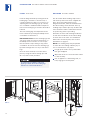
MOLDING INSTALLATION
The decorative white molding strips for the
side and top of the unit can be snapped into
place. The top molding strip used on
Integrated tall units, must be installed before
the side molding can be attached. The top
molding strip is held in place by double-sided
velcro fasteners. Refer to illustration 8 below
for positioning of the top molding.
Illustration 9 shows side molding installation
for tall units. Installation of the side molding
for base units is the same. For installations
where units are side by side, refer to Dual
Installations on page 21.
NOTE:
The molding strips may be painted
to match the surrounding cabinetry, if you
choose. Follow these easy steps:
Rough up the surface to be painted with
fine grit sandpaper.
Wipe with alcohol to ensure that the surface
is clean and dry.
Use an appliance or industrial grade, oil
base, high gloss enamel paint.
INTEGRATED INSTALLATION INSTRUCTIONS
LEVEL THE UNIT
Level the Integrated unit by turning the front
leveling legs clockwise to raise the unit, or
counterclockwise to lower it. To assist you in
adjusting the front leveling legs up or down,
use a standard screwdriver blade and place it
in the front leveling leg as shown in illustration
6 below.
The rear leveling legs are adjusted from the
front of the base by turning the Phillips head
screw. Refer to illustration 7.
IMPORTANT NOTE:
The rear leveling legs will
only move 2 mm for every 18 revolutions on
the Phillips head screw. Do not over torque.
Use the lowest torque setting on any power
screwdriver. Do not turn the rear leveling legs
by hand. Damage will occur if you turn these
legs.
Once the unit is leveled, secure the unit in
place by using the side mounting clips and
#8 x 12,7 mm screws provided.
To reduce the possibility of the unit
tipping forward, the front leveling legs
must be in contact with the floor.
Top Molding
Illus. 6 Illus. 7 Illus. 8
Illus. 9

17
In areas with water of high mineral content,
the use of an in-line water filter is recom-
mended. Make sure the filter is positioned and
accessible for replacement when necessary.
IMPORTANT NOTE:
The ice maker will not
fill with water immediately. Allow 24 hours for
proper ice production. Let your customer know
that the first container filled with ice should be
discarded, as with any new connection there
may be impurities in the ice from the water
supply line.
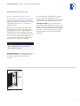
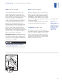
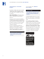
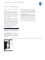
WATER LINE CONNECTION
QUICK CONNECT WATER VALVE
For units with an ice maker, the quick connect
water valve and PEX tubing are located on the
right-hand side of the unit towards the bottom.
Follow these instructions to connect the ice
maker water line.
Attach the union fitting to the copper house
water supply line. Pull the coiled gray PEX
tubing with a red cap and captured metal nut
toward the house water supply line. Remove
and discard the red cap, then attach the tubing
to the union with captured nut. Tighten all
connections. Recoil the excess tubing under
the unit. Refer to illustration 10 below.
IMPORTANT NOTE:
Turn on the water supply
and check all fittings for leaks. Make certain
the electrical harness is attached to the
solenoid.
INTEGRATED INSTALLATION INSTRUCTIONS
PEX
Tubing
Illus. 10
Shut power off at the circuit breaker
before making electrical connection to
the solenoid, if required.

18
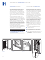
PANEL INSTALLATION
The integrated design uses custom wood or
other decorative panels and handles provided
by the customer. Stainless steel panels
are available as sales accessories through your
Sub-Zero dealer. To obtain local dealer infor-
mation, visit our website, subzero.com.
Before beginning installation, check the panels
for the proper fit and finish desired.
Door and drawer panels must be a minimum
of 16 mm thick. The door panel cannot exceed
18 kg and each drawer panel must not exceed
5 kg for 686 mm wide units. For 914 mm wide
units, the door panel weight limit is 24 kg and
7 kg for each drawer panel.
D-style pulls are recommended for handle
hardware. Handles should be located on the
opposite side from the hinge, centered on the
cabinet door, and on the top center area of the
drawer panel. Screw heads may have to be
countersunk to ensure that the hardware does
not interfere with the panels fitting flush with
the unit's door or drawers.
It is recommended that the door panel of the
tall unit be installed first and then the upper
and lower drawer panels.
INTEGRATED INSTALLATION INSTRUCTIONS
PANEL
REQUIREMENTS
Door and drawer
panels must be a
minimum of 16 mm
thick.
The door panel
cannot exceed 18 kg
and each drawer
panel must not
exceed 5 kg for 686
mm wide units. For
914 mm wide units,
the door panel
weight limit is 24 kg
and 7 kg for each
drawer panel.
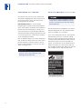
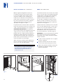
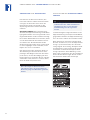
KICKPLATE /GRILLE INSTALLATION
Once your Integrated unit is secured, the
kickplate/grille can be installed. There is some
adjustment to the mounting assembly so that
this decorative piece can fit flush with the
surrounding area. Refer to illustration 11
below.
Turn power back on to the electrical outlet.
IMPORTANT NOTE:
The unit must be allowed
to have ventilation through the fins of the kick-
plate/grille. You may cover the solid area, but
do not block the fins. The lower drawer panel
may hang in front of the fins, but your base-
board molding must not cover them.
IMPORTANT NOTE:
The kickplate/grille must
be removed for servicing. The floor cannot
interfere with removal.
NOTE:
The kickplate/grille can be painted
another color, if you choose. Follow these
easy steps:
Rough up the surface to be painted with
fine grit sandpaper.
Wipe with alcohol to ensure that the surface
is clean and dry.
Use an appliance or industrial grade, oil
base, high gloss enamel paint.
Back Of Door Panel
Bottom Of Template
Flush With Bottom
Of Door Panel
Gap On Side
Edges Will Vary
According To
Design
Illus. 11
Illus. 12

19
PANEL INSTALLATION
If you have questions, contact your Sub-Zero
dealer or cabinet supplier. Additional panel
information can be found in the Sub-Zero
Design Guide.
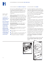
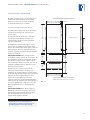
DOOR PANEL INSTALLATION
Remove the two pieces of mounting hardware
attached to the front of the door and set aside.
Place the door panel lying face down on a
protected surface to ensure that the front is not
scratched or damaged.
Position the plastic template provided flush
with the lower edge of the door. Be sure you
are following the exact location for the right-
hand (RH) or left-hand (LH) door position.
Refer to illustration 12 on page 18.
IMPORTANT NOTE:
The template has two
usable sides, one side for the door and one for
the drawers. Make sure you use the proper
holes and side. Remember you are viewing the
door panel from the back side in illustration 12
on page 18.
Once you have located the proper position for
the bracket, mark the pilot holes, remove the
template and drill pilot holes for mounting the
bracket. It is best to start with a few holes,
position the bracket, drill the remaining pilot
holes and then secure the mounting bracket
with the #8 x 12,7 mm screws provided. Illus-
tration 13 shows the mounting hardware
location for door and drawer panels.
IMPORTANT NOTE:
Dimensions in illustration
13 are based on a 3 mm reveal. A reveal of up
to 6 mm is possible, but panel dimensions
need to be adjusted accordingly.
INTEGRATED INSTALLATION INSTRUCTIONS
1153
mm*
345
mm
424
mm*
132
mm
135
mm
214
mm
287
mm
32
mm
32
mm
570
mm
679 mm*
FOR 686 mm WIDE UNITS
908 mm* FOR 914 mm WIDE UNITS
606 mm* FOR 686 mm WIDE UNITS
835 mm* FOR 914 mm WIDE UNITS
VIEW FROM BACK OF PANELS
*DIMENSIONS MAY VARY
PANEL BRACKET POSITIONING
LH DOOR SWINGRH DOOR SWING
37 mm*
Exercise caution when drilling holes for
mounting hardware. This is especially
critical with inset panels.
Illus. 13

DRAWER PANEL INSTALLATION
Remove the mounting hardware provided and
set aside. As with the door panel, you should
work on the back side of each drawer panel
and protect the fronts of these panels.
Position the top edge of the template flush
with the top edge of each drawer. For the top
drawer, there is only one location for the lower
mounting bracket to be placed. However, the
bottom drawer allows a second option, invert-
ing the lower mounting bracket, depending on
the height and thickness or detail of the panel.
Refer to illustration 15 below.
Secure the template in place with tape or a
small clamp and mark positions for the pilot
holes. Remove the template and drill the pilot
holes. Place the mounting brackets in the
proper location with the tabbed bracket on top
and ’L’ bracket on the bottom of the panel.
Fasten brackets securely with the #8 x 12,7
mm screws provided. Refer to illustration 16
below. Illustration 13 on page 17 also shows
the mounting hardware location for drawer
panels.
20
INTEGRATED INSTALLATION INSTRUCTIONS
PANEL
REQUIREMENTS
Door and drawer
panels must be a
minimum of 16 mm
thick.
The door panel
cannot exceed 18 kg
and each drawer
panel must not
exceed 5 kg for 686
mm wide units. For
914 mm wide units,
the door panel
weight limit is 24 kg
and 7 kg for each
drawer panel.
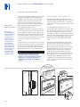
PANEL INSTALLATION
Before attaching the door panel to the door,
place two screws in the center of each
mounting position, just enough that the slotted
holes on the hinge side door panel bracket will
slide under the heads. These positioning
screws will support the door panel during
installation and adjustment. Refer to illustra-
tion 14 below.
Install the door panel by engaging the tabbed
bracket to the handle side of the door first and
then sliding the hinge side mounting bracket
onto the positioning screws on the hinge side
of the door. The panel can be adjusted 6 mm
up and down and side to side.
Once the door panel is in place and adjusted
correctly, attach the six remaining #10 x 12,7
mm screws to the hinge side mounting bracket
and install the magnetic decorative caps as
shown in illustration 14.
As the reveal between cabinets and the
unit decreases, the potential exists for
severe finger pinching if fingers are placed
in the opening when the door is closing.
Back Of
Drawer Panel
Gap On Side
Edges Will Vary
According To
Design
Top Of Template
Flush With Top Of
Drawer Panel
Illus. 14 Illus. 15 Illus. 16

21
PANEL INSTALLATION
To help with the placement of the drawer
panels, examine the lower ’L’ bracket and
panel to determine the slotted holes on the
bracket that will be used. Then position screws
into the lower portion of the drawer that
correspond with these slots. Leave these
screws out just enough that the slotted holes
in the bracket will slide under the heads.
With the two mounting brackets in place,
install the drawer panel by engaging the top
tabbed bracket first, then slide the lower ’L’
bracket onto the positioning screws. Each
drawer panel can be adjusted 6 mm up and
down and side to side. Fasten all screws to the
lower ’L’ bracket to secure the drawer panel.
Refer to illustration 16 on page 20.
IMPORTANT NOTE:
Once drawer panels have
been adjusted for proper spacing, be sure to
reconnect the control cable on the base unit
only after you have installed the drawer. Refer
to illustration 3 on page 14.
DUAL INSTALLATIONS
When two Integrated units are installed closer
than 51 mm to one another, it is necessary to
use the Sub-Zero dual installation heater kit
(ICBBBDUAL or ICBTTDUAL). The heater plate
from this kit must be attached to the left side
exterior of the right hand unit before the units
are slid into position.
Contact your Sub-Zero dealer for the proper
components and installation instructions.
90-DEGREE DOOR STOP
All Integrated tall units have a 90-degree door
stop built into the hinge system. Use the blade
edge of a standard screwdriver and rotate the
brass cam in the center portion of the hinge
until you reach the stop. You must make this
adjustment to both the bottom and top hinge.
Refer to illustration 17 below.
INTEGRATED INSTALLATION INSTRUCTIONS
Illus. 17
Exercise caution when drilling holes for
mounting hardware. This is especially
critical with inset panels.
ACCESSORIES
Optional acces-
sories are available
through your
Sub-Zero dealer. To
obtain local dealer
information, visit
our website,
subzero.com.

22
INSTALLATION CHECKLIST
The importance of the installation of the
Sub-Zero Integrated unit cannot be
overemphasized. Proper installation is the
responsibility of the selling dealer or installer.
IMPORTANT NOTE:
To ensure a safe and
proper installation, the following checklist
should be completed by the installer to ensure
that no part of the installation has been
overlooked.
Advise the homeowner to fill out and return all
product registration forms. This will ensure
that the customer information is in our
database in the event service is required.
Any questions or problems about the installa-
tion should be directed to your Sub-Zero
dealer. You can also visit our website at
subzero.com.
INSTALLATION CHECKLIST
INSTALLATION CHECKLIST
Has the anti-tip bracket been installed
properly and is it making contact with
the unit?
Is the unit level? Are all leveling legs
making contact with the floor?
Is the power cord plugged into a properly
grounded 3-prong outlet, which has been
installed in accordance with all applicable
electrical codes?
Is the water supply connected for units with
an automatic ice maker? Have you checked
for leaks?
Has the kickplate/grille been installed
properly?
Are panels attached securely and properly
aligned?
Has the door been aligned for proper
appearance and operation?
Have all accessories been installed?
Have any installation or service problems
been noted on the product registration
card? Has the registration card been
mailed in?
Have stainless steel panels been inspected
for any imperfections? This is to be done by
the dealer or installer with the customer
upon completion of the installation.
NOTE: Classic, platinum and carbon stain-
less steel panels are covered by a limited
60-day parts and labor warranty for
cosmetic defects.
Page is loading ...
Page is loading ...
Page is loading ...
Page is loading ...
Page is loading ...
Page is loading ...
Page is loading ...
Page is loading ...
Page is loading ...
Page is loading ...
Page is loading ...
Page is loading ...
Page is loading ...
Page is loading ...
Page is loading ...
Page is loading ...
Page is loading ...
Page is loading ...
Page is loading ...
Page is loading ...
Page is loading ...
Page is loading ...
Page is loading ...
Page is loading ...
Page is loading ...
Page is loading ...
Page is loading ...
Page is loading ...
Page is loading ...
Page is loading ...
Page is loading ...
Page is loading ...
Page is loading ...
Page is loading ...
Page is loading ...
Page is loading ...
Page is loading ...
Page is loading ...
Page is loading ...
Page is loading ...
Page is loading ...
Page is loading ...
Page is loading ...
Page is loading ...
Page is loading ...
Page is loading ...
Page is loading ...
Page is loading ...
Page is loading ...
Page is loading ...
Page is loading ...
Page is loading ...
Page is loading ...
Page is loading ...
Page is loading ...
Page is loading ...
Page is loading ...
Page is loading ...
Page is loading ...
Page is loading ...
Page is loading ...
Page is loading ...
Page is loading ...
Page is loading ...
Page is loading ...
Page is loading ...
Page is loading ...
Page is loading ...
Page is loading ...
Page is loading ...
Page is loading ...
Page is loading ...
Page is loading ...
Page is loading ...
Page is loading ...
Page is loading ...
Page is loading ...
Page is loading ...
Page is loading ...
Page is loading ...
Page is loading ...
Page is loading ...
-
 1
1
-
 2
2
-
 3
3
-
 4
4
-
 5
5
-
 6
6
-
 7
7
-
 8
8
-
 9
9
-
 10
10
-
 11
11
-
 12
12
-
 13
13
-
 14
14
-
 15
15
-
 16
16
-
 17
17
-
 18
18
-
 19
19
-
 20
20
-
 21
21
-
 22
22
-
 23
23
-
 24
24
-
 25
25
-
 26
26
-
 27
27
-
 28
28
-
 29
29
-
 30
30
-
 31
31
-
 32
32
-
 33
33
-
 34
34
-
 35
35
-
 36
36
-
 37
37
-
 38
38
-
 39
39
-
 40
40
-
 41
41
-
 42
42
-
 43
43
-
 44
44
-
 45
45
-
 46
46
-
 47
47
-
 48
48
-
 49
49
-
 50
50
-
 51
51
-
 52
52
-
 53
53
-
 54
54
-
 55
55
-
 56
56
-
 57
57
-
 58
58
-
 59
59
-
 60
60
-
 61
61
-
 62
62
-
 63
63
-
 64
64
-
 65
65
-
 66
66
-
 67
67
-
 68
68
-
 69
69
-
 70
70
-
 71
71
-
 72
72
-
 73
73
-
 74
74
-
 75
75
-
 76
76
-
 77
77
-
 78
78
-
 79
79
-
 80
80
-
 81
81
-
 82
82
-
 83
83
-
 84
84
-
 85
85
-
 86
86
-
 87
87
-
 88
88
-
 89
89
-
 90
90
-
 91
91
-
 92
92
-
 93
93
-
 94
94
-
 95
95
-
 96
96
-
 97
97
-
 98
98
-
 99
99
-
 100
100
-
 101
101
-
 102
102
-
 103
103
-
 104
104


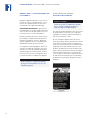
Sub-Zero ICB700TR User manual
- Type
- User manual
Ask a question and I''ll find the answer in the document
Finding information in a document is now easier with AI
in other languages
- italiano: Sub-Zero ICB700TR Manuale utente
- français: Sub-Zero ICB700TR Manuel utilisateur
- español: Sub-Zero ICB700TR Manual de usuario
- Deutsch: Sub-Zero ICB700TR Benutzerhandbuch
Related papers
-
Sub-Zero ICBB-36R User manual
-
Sub-Zero Sub-Zero 424FS User manual
-
Sub-Zero Refrigerator 427RG User manual
-
-
Sub-Zero 700 Series Refrigeration User manual
-
-
Sub-Zero 400 Series Wine Storage User manual
-
Sub-Zero IT-36CIID-LH Installation guide
-
-
Sub-Zero IT-36R-LH Installation guide
Other documents
-
Wolf R486G User manual
-
 Kichler Lighting 15607AZT User manual
-
No Brand KITFIANCHI User manual
-
Rev-A-Shelf 53WC-1535SCDM Installation guide
-
Groupe Brandt TCB310R Owner's manual
-
-
-
-
 SunnyTent OVAL User manual
-
Masonite 76422 User manual

