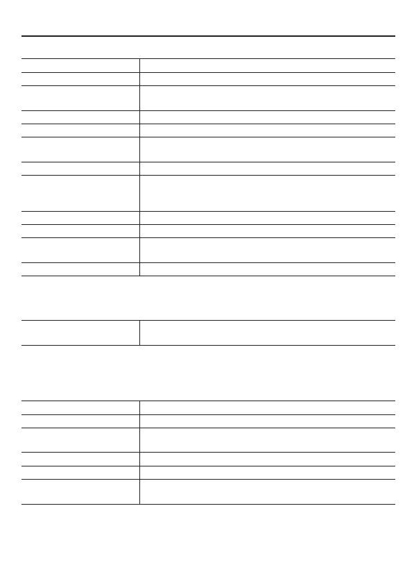
Sanyo HD2100 User manual

Category
Bridge cameras
Type
User manual
SUMMARY MANUAL
Side A
Megapixel Camera
VCC-HD2500P/HD2500
VCC-HD2300P/HD2300
VCC-HD2100P/HD2100
THIS INSTALLATION SHOULD BE MADE BY A QUALIFIED
SERVICE PERSON AND SHOULD CONFORM TO ALL LOCAL
CODES.
Please read this instruction manual carefully in order to ensure correct installation.
In addition, be sure to read carefully the electronic manual (INSTRUCTION MANUAL)
contained in the supplied CD-ROM to ensure correct operation of the camera.
EnglishFrançaisEspañolDeutschЁ᭛ㅔԧ
1
Table of Contents
Name and Function of Each Component .................................................................2
Basic Connections .................................................................................................... 5
Alarm Terminal Connections .....................................................................................6
Lens Adjustment ....................................................................................................... 7
Network Settings ....................................................................................................10
Specifications ......................................................................................................... 11
Copyright Notice .............................................................See “Side B” of this manual.
Check your operating environment.
To operate the camera via network operation, you must meet the following operating
requirements.
PC
: IBM PC/AT compatible
Operating system
: Windows XP Professional/Windows Vista
CPU
: Core2Duo E6700 2.66 GHz or higher
Memory
: Windows XP: 1GB or more
Windows Vista: 2GB or more
Network interface
: 10Base-T/100Base-TX (RJ-45 connector)
Display card
: 1920×1200 pixels or higher
Graphics chip
: ATI RADEON HD2600 series or higher
nVIDIA GeForce 8600 series or higher
nVIDIA Quadro FX550 series or higher
Web browser
: Internet Explorer Ver. 6.0 SP2 or higher,
or Internet Explorer Ver. 7.0
You can automatically set up the IP address of the camera.
This software application is useful when two or more cameras are connected to the
network.
Download “AUTO IP SETUP” software application from the supplied CD-ROM.
Accessories
Video Cable
Cable holder for wiring
CD-ROM
Clamping Core
To prevent electromagnetic interference
VCC-HD2500P VCC-HD2300P
VCC-HD2100P
2
Name and Function of Each Component
Rear Face
AUDIO
DC12V
CLASS 2
WIRING
SD (SDHC) Card Slot (VCC-HD2500P/HD2500)
Audio Output Jack (AUDIO OUT, 3.5-mm mini jack) (VCC-HD2500P/HD2500)
Power Indicator (POWER)
The power indicator blinks to indicate the following camera statuses.
Recording to SD memory card stopped/camera is recognizing SD memory card/
An error occurred
Firmware update in progress
Power Terminals (24 V AC/12 V DC)
Audio Input Jack (AUDIO IN, 3.5-mm mini jack) (VCC-HD2500P/HD2500)
Network Socket (LAN, RJ-45)
Access indicator
Lights: Connection has been established between the camera
and the network.
Blinks: Data are being transmitted via the network.
Speed indicator
Lit: 100BASE-TX
Unlit: 10BASE-T
Control Terminals (ALARM IN/OUT: 6 push-lock pins)
These terminals can be used as alarm input or Day/Night switching terminals.
Monitor Output Socket (MONITOR OUT)
3
Side Face
NEAR
FAR
SET
RESET
Operation Buttons
Restarting camera: Press the RESET button.
OPTION SETTINGS (CAMERA REBOOT)
Stopping recording/Removing SD memory card: Press the NEAR button for
2 seconds or more.
The power indicator starts blinking and then stays lit when the camera is ready for
you to remove the SD memory card.
SD MEMORY CARD
Resuming stopped recording/Having camera recognize SD memory card:
Press the FAR button for 2 seconds or more.
The power indicator starts blinking and then stays lit when the camera has
recognized the SD memory card.
Restoring factory default settings: Press the NEAR and SET buttons
simultaneously.
OPTION SETTINGS (FACTORY DEFULT)
Resetting login password (for default users only): Press the FAR and SET
buttons simultaneously.
Restoring factory default back focus position: Press the NEAR and FAR
buttons simultaneously.
CAMERA SETTING (FOCUS ASSIST)
Adjusting focus/Adjusting iris
Page 7, “Lens Adjustment” section or the CAMERA SETTINGS (FOCUS
ASSIST/IRIS SETTING) section on the electronic manual.
Viewing Firmware Version:
“Viewing Firmware Version” section or the OPTION SETTINGS (FIRMWARE
UPDATE) section on the electronic manual.
SD memory card: SD card
Name and Function of Each Component
4
Name and Function of Each Component
Auto Iris Lens Socket (LENS)
Connect the lens cable plug to the auto iris lens socket provided on the left-side face of
the camera.
It is recommended that you use a CS-mount DC auto iris megapixel lens (commercially
available).
LENS terminal for auto iris lens
Brake coil (+)
Drive coil (–)
Brake coil (–)
Drive coil (+)
5 mm max.
Keep the lens clean at all times.
The conversion ring (commercially available) is required to use a C-mount
lens.
The lens cable plug must be changed if it does not fit into the auto iris
lens socket. If so, contact the distributor from which you purchased the
product (or the agent that provides the installation service).
Bracket
This bracket may be attached to either the top or bottom face of the camera as shown
in the figure.
When you install the camera, make sure that the screws can securely fix the camera to
the bracket.
Install the camera mount (commercially available) securely to a durable
location, taking into account the total weight of the camera mount and the
camera.
5
Basic Connections
AUDIO
DC12V
CLASS2
WIRING
LAN
OUTIN
12
COM
12
ALARM
POWER
AC24V
AC24V
GND
AC24V
AC24V
GND
AC24V
AC24V
GND
VCC-HD2500P
VCC-HD2300P
VCC-HD2100P
24 V AC
12 V DC
Power supply
Monitor
PC
VCC-HD2500P
VCC-HD2500
24 V AC
12 V DC
Power Connection
Connect the power terminals (24 V AC/12 V DC) of the camera to a power supply.
Connection to 24 V AC power supply
Although the power terminals have no polarity, the earth grounding wire must be
connected to the GND (earth grounding) terminal.
Connection to 12 V DC power supply
Note the polarity (+/–) of the power terminals when connecting the camera to a
12 V DC power supply.
Incorrect polarity may cause damage to the camera.
Be sure to use an 18AWG or thicker wire power cable.
If you want to use PoE to supply power, do not connect to AC/DC power
supply.
Network Connection
This camera is designed so that you can use all of its functions via network
operation.
By connecting the network (LAN) socket of the camera to your PC using a LAN
cable, you can configure and operate it from the Web browser installed on your PC.
Camera Monitor Connection (“Lens Adjustment” Page 7)
A monitor can be connected to perform focus adjustment with the camera.
Connect the monitor output socket (MONITOR OUT) of the camera to a monitor via
the monitor cable. After adjustment, be sure to remove the monitor cable.
6
To connect a cable, while pushing the protrusion of the terminal, insert the cable into
the opening and then release it.
External
peripheral
device
Alarm input
signal
Alarm input
signal
(COM)
(COM)
(COM)
(ALARM OUT 1)
(ALARM OUT 2)
(ALARM IN 1)
(ALARM IN 2)
Alarm Output Terminal Connection
Connect a buzzer, lamp, or other alarm device to one of the alarm output terminals
(ALARM OUT 1 or 2).
After connecting an alarm device, configure the output conditions
for the corresponding alarm output terminal (ALARM OUT 1 or 2) via
network operation on the ALARM SETTINGS screen.
Alarm output terminal configuration is also possible via remote
operation.
Alarm Input Terminal Connection
Connect an alarm switch, infrared sensor, or other external device to one of the
alarm input terminals (ALARM IN 1 or 2).
After connecting an alarm device, configure the input conditions for
the corresponding alarm input terminal (ALARM IN 1 or 2) via network
operation on the ALARM SETTINGS screen.
VCC-HD2500P/HD2500/HD2300P/HD2300:
To use the alarm input terminals as Day/Night switching terminals, follow
the steps below.
Under [DAY/NIGHT], set [DAY/NIGHT] to “COLOR” and select the
terminal you want to use in [EXT ALARM].
On the ALARM SETTINGS screen, in [POLARITY], select the signal
polarity of the alarm input terminal.
Alarm Terminal Connections
7
Lens Adjustment
For high-resolution megapixel images, the focus assist function is useful to obtain a
precise focus because otherwise it is extremely difficult.
If you are using a varifocal lens, adjust the focus using the following procedure.
If the focus assist function does not work properly because the camera
produces too dark or too bright video images, perform iris adjustment in
advance.
Press the SET button for 2 seconds or more.
The monitor now shows the SELECT MENU screen.
NEAR FAR
SET
RESET
SELECT MENU
FOCUS ASSIST
IRIS
FIRMWARE VERSION
NEAR UP
FAR DOWN
SET SELECT
On the SELECT MENU screen, all information is displayed in English.
Select [FOCUS ASSIST] using the NEAR/FAR button and press the SET
button.
The monitor now shows the focus adjustment screen.
Use the zoom lever of the lens to adjust the angle of view and the focus
lever of the lens to set the FA bar to the maximum level.
When the subject comes into focus, the color of the status indicator
“FOCUSING” turns from black to orange.
If the use of the focus lever does not provide precise focusing, follow the “Fine-
adjusting focus” procedure on the next page.
FOCUSING
PEAK HOLD XXXX
INDICATOR XXXX
NEAR FAR
FOCUSING
PEAK HOLD XXXX
INDICATOR XXXX
NEAR FAR
PEAK HOLD: Shows the value of the maximum focus level.
INDICATOR: Shows the value of the current focus level.
8
Lens Adjustment
Fine-adjusting focus (using buttons provided on side face)
NEAR FAR
SET
RESET
Use the zoom lever of the lens to adjust the angle of view and the focus
lever of the lens to roughly focus on the subject.
Press the SET button. (Focus adjustment screen Page 7)
The camera automatically focuses on the subject. Note that the color of the status
indicator “FOCUSING” turns from black to orange.
If the camera failes to focus on the subject, the FA bar will not operate normally
with the status indicator showing “ERROR”. In this case, manually adjust the
focus. (
Electronic manual)
Press the NEAR/FAR button to adjust the focus.
Pressing the button causes the back focus position to change, which is indicated
in the FB bar gauge .
The position changes step by step each time the button is pressed and
continuously at a high speed when the button is held down.
If you want to restore the default back focus position in re-
adjustment, etc., press the NEAR and FAR buttons simultaneously.
While the camera is initializing the back focus position, the status
indicator shows “INITIALIZING”.
Press the SET button for 2 seconds or more.
The focus adjustment screen will close and the SELECT MENU screen reappears.
The focus adjustment screen will also close automatically if left idle
for 5 minutes or more.
VCC-HD2500P/HD2500/HD2300P/HD2300:
Adjust the focus using the following procedure when the camera
fails to focus on the subject in color or black-and-white mode.
Select [FOCUS ASSIST] on the CAMERA SETTINGS screen and
make sure that “AUTO” is set for [COLOR/B/W].
Adjust the focus in color or black-and-white mode.
9
Adjusting iris
If the camera produces too dark, too bright, or other incorrect video images, adjust the
lens iris.
Press the SET button for 2 seconds or more.
The monitor now shows the SELECT MENU screen.
NEAR
FAR
SET
SELECT MENU
FOCUS ASSIST
IRIS
FIRMWARE VERSION
NEAR UP
FAR DOWN
SET SELECT
On the SELECT MENU screen, all information is displayed in English.
Select [IRIS] using the NEAR/FAR button and press the SET button.
The monitor now shows the iris adjustment screen.
IRIS
LEVEL
DARK LIGHT
------ú--------40
NEAR LEFT
FAR RIGHT
IRIS
LEVEL
DARK LIGHT
------ú--------40
NEAR LEFT
FAR RIGHT
NEAR
FAR
SET
Press the NEAR/FAR button to adjust the iris level.
The position changes step by step each time the button is pressed and
continuously at a high speed when the button is held down.
NEAR: Closes the iris to produce darker images.
FAR: Opens the iris to produce brighter images.
Press the SET button for 2 seconds or more.
The iris adjustment screen will be closed.
The iris adjustment screen will also close automatically if left idle for
5 minutes or more.
Lens Adjustment
10
Network Settings
Preparing Your Computer for Network Operation
Check your operating environment. (
Page 1)
Connect the camera to the network to which your PC is also connected.
Configue the network information on your PC.
Configure information such as the IP address of your PC.
Install the “H.264 Plug-in” from the supplied CD-ROM onto your PC.
You are now ready to monitor the surveillance video in the H.264 format.
Start Internet Explorer.
The supported Web browser is Internet Explorer Ver.6.0 SP2 or higher, or Internet
Explorer Ver.7.0.
Access the camera from your Web browser.
From your Web browser (Internet Explorer), access the camera and log into the
system as an “admin” user (administrator).
In the address bar, type the IP address of the camera and press [Enter] key.
When you access the camera, the login screen appears.
If this is the first access to the camera, in the Address bar, enter the default IP
address as follows.
If you set [SSL] to “ON”, before the IP address, type “https://” (instead
of “http://”).
Attempts to access the camera using the default IP address will fail if
that address is already being used by another device in the network.
If so, change the IP address of the existing device before accessing
the camera.
11
Type your user name and password and click [OK].
The language selection screen appears.
If this is the first access to the camera, log in as an admin user
(administrator) using the following default authentication information.
User name: admin
Password: admin
Click the button corresponding to the language you want to use.
The live screen appears.
From the second login onwards, the live screen appears automatically by skipping
the language selection screen.
If this is the first access to the camera, configure the system clock on the CLOCK
SETTINGS screen.
Network Settings
12
Specifications
Camera
Image pickup device 1/3" CMOS sensor
Effective pixels 16:9 1920 (H)×1080 (V), 4:3 2288 (H)×1712 (V)
Lowest image illumination 50IRE: 1.0 lx (at F1.2, color mode, high gain)
50IRE: 0.1 lx (at F1.2, black-and-white mode, high gain)
Video S/N ratio 50dB (when AGC is “OFF”)
Lens mount CS mount
Flange back adjustment 12.5 ± 0.5 mm, electrical flange back adjustment (Focus
assist function)
Iris control DC iris lens supported
Digital PTZ
(VCC-HD2500P/HD2500)
Enables electronic pan, tilt, and zoom operations on
clipped subject areas in VGA size.
Zoom magnification: max. 2X
Mirror H/V/HV/OFF
Privacy mask On/Off, max. 8 mask patterns
Motion sensor On (Motion masking/motion detection area setting, or
video analytics)/Off, face detection function supported
Language selection English, French, German, Spanish, Japanese
For further details on the specifications of the camera, refer to the electronic manual.
SD Recording (SD Memory Card) (VCC-HD2500P/HD2500)
Recording mode Alarm recording, backup recording in event of a network
failure
For the recommended SD memory cards, visit our website.
http://www.sanyo-cctv.net/
I/O
Video output Composite output (NTSC equivalent/ PAL equivalent)
LAN 10BASE-T/100BASE-TX (RJ-45 connector)
Card slot
(VCC-HD2500P/HD2500)
1 (SDHC compliant, max. 32 GB supported)
Alarm input 2 (NO/NC), also serving as Day/Night switching terminal
Alarm output 2 (NO/NC, 16V, 150 mA, open collector)
Audio input/output
(VCC-HD2500P/HD2500)
Microphone input (3.5-mm mini jack)
Line output (3.5-mm mini jack)
13
Specifications
Network
Image/video compression H.264/JPEG
Video size (H.264) (16:9) 1920×1080, 1280×720, 640×360, 320×180
(4:3) 1600×1200, 1280×960, 1024×768, 640×480,
320×240
Video size (JPEG) (16:9) 1920×1080, 1280×720, 1024×576, 640×360
(4:3) 2288×1712, 1600×1200, 1280×960, 1024×768,
800×600, 640×480, 320×240
Picture quality QUALITY mode: BASIC, NORMAL, ENHANCED, FINE,
SUPER FINE
BITRATE mode: User-specified bit rate
Interface 10BASE-T/100BASE-TX
Protocol TCP/IP, UDP, HTTP, HTTPS, SMTP, NTP, DHCP, FTP,
DDNS, RTP, RTSP, RTCP
Audio G.711 (Bidirectional)
Simultaneous access 20
Security BASIC authentication (ID/password), SSL, IP filtering
Others
Operating ambient
temperature/humidity
–10 to +50ºC/14 to 122ºF,
90% RH or less (no condensation)
Power source 12 to 15 V DC/24 V AC ± 10%, 50/60 Hz, PoE
Power consumption 6.8W (VCC-HD2500P/HD2500)
4.6W (VCC-HD2300P/HD2300, VCC-HD2100P/HD2100)
Weight 250 g/8.8 oz. (VCC-HD2500P/HD2500)
220 g/7.8 oz. (VCC-HD2300P/HD2300, VCC-HD2100P/
HD2100)
Dimensions
1/4"-20UNC
72
(2.8)
45 (1.8)
85 (3.3)
75 (3.0)
11 (0.4)
Unit: mm (inch)
Appearance and specifications are subject to change without prior notice or
obligations.
MANUEL ABRÉGÉ
Côté A
Caméra à mégapixels
VCC-HD2500P/HD2500
VCC-HD2300P/HD2300
VCC-HD2100P/HD2100
CETTE INSTALLATION DOIT ETRE EFFECTUEE PAR UNE
PERSONNE QUALIFIEE DU SERVICE TECHNIQUE ET DOIT
ETRE CONFORME A TOUS LES CODES LOCAUX.
Veuillez lire ce manuel d’instructions tres attentivement afin d’effectuer une
installation correcte. Veuillez egalement lire tres attentivement le manuel
electronique (INSTRUCTION MANUAL) contenu dans le CD-ROM afin de faire
fonctionner la camera correctement.
EnglishFrançaisEspañolDeutschЁ᭛ㅔԧ
MANUAL DE RESUMEN
Lado A
Cámara de megapíxeles
VCC-HD2500P/HD2500
VCC-HD2300P/HD2300
VCC-HD2100P/HD2100
LA INSTALACIÓN TIENE QUE SER REALIZADA POR
UNA PERSONA DE SERVICIO Y TIENE QUE ESTAR DE
ACUERDO CON LOS CÓDIGOS LOCALES.
Leer atentamente este manual de instrucciones para garantizar que se realiza una
instalación correcta. Además, es preciso leer atentamente el manual electrónico
(INSTRUCTION MANUAL) contenido en el CD-ROM para garantiza que se utiliza
correctamente la cámara.
EnglishFrançaisEspañolDeutschЁ᭛ㅔԧ
1
目录
每个组件的名称与功能 .............................................................................................. 2
基本连接 ................................................................................................................... 5
报警端子连接 ............................................................................................................ 6
镜头调节 ................................................................................................................... 7
网络设置 ................................................................................................................. 10
规格 ........................................................................................................................ 11
版权声明 ........................................................................... 参见本手册的“第B面”。
检查操作环境。
བ㽕䗮䖛㔥㒰᪡԰ᨘڣ༈ˈ߭ᖙ乏⒵䎇ϟ߫᪡԰⦃๗㽕∖DŽ
计算机
: ϢIBM PC/ATݐᆍ
操作系统
: Windows XP Professional/Windows Vista
CPU
: Core2Duo E6700 2.66 GHz៪݊ҹϞ
内存
: Windows XP: 1GB1GBҹϞ
Windows Vista: 2GB2GBҹϞ
网络接口
: 10Base-T/100Base-TX (RJ-45䖲᥹఼)
显卡
: 1920h1200ڣ㋴៪᳈催
图形芯片
: ATI RADEON HD2600㋏߫៪᳈催
nVIDIA GeForce 8600㋏߫៪᳈催
nVIDIA Quadro FX550㋏߫៪᳈催
Web浏览器
: Internet Explorer Ver.6.0 SP2៪᳈催⠜ᴀˈ
Internet Explorer Ver. 7.0
可以自动设置摄像头的IP地址。
೼ϸϾ៪ϸϾҹϞⱘᨘڣ༈䖲᥹ࠄ㔥㒰ᯊˈৃՓ⫼ℸ䕃ӊᑨ⫼⿟ᑣDŽ
ϟ䕑䰘ᏺⱘCD-ROMܝⲬЁࣙ৿ⱘĀAUTO IP SETUPā䕃ӊᑨ⫼⿟ᑣDŽ
附件
㾚乥⬉㓚
⫼ᴹᏗ㒓ⱘ⬉㓚ᬃᶊ
CD-ROM
व὿ሣ㬑⦃
䰆ℶ⬉⺕ᑆᡄ
VCC-HD2500P VCC-HD2300P
VCC-HD2100P
SANYO Electric Co., Ltd.
Printed in China
1AC6P1P4018-A
L5DB2, L5DJ2 (0909KR-CA)
  • Page 1 1
  • Page 2 2
  • Page 3 3
  • Page 4 4
  • Page 5 5
  • Page 6 6
  • Page 7 7
  • Page 8 8
  • Page 9 9
  • Page 10 10
  • Page 11 11
  • Page 12 12
  • Page 13 13
  • Page 14 14
  • Page 15 15
  • Page 16 16
  • Page 17 17
  • Page 18 18
  • Page 19 19
  • Page 20 20
  • Page 21 21
  • Page 22 22
  • Page 23 23
  • Page 24 24
  • Page 25 25
  • Page 26 26
  • Page 27 27
  • Page 28 28
  • Page 29 29
  • Page 30 30
  • Page 31 31
  • Page 32 32
  • Page 33 33
  • Page 34 34
  • Page 35 35
  • Page 36 36
  • Page 37 37
  • Page 38 38
  • Page 39 39
  • Page 40 40
  • Page 41 41
  • Page 42 42
  • Page 43 43
  • Page 44 44
  • Page 45 45
  • Page 46 46
  • Page 47 47
  • Page 48 48
  • Page 49 49
  • Page 50 50
  • Page 51 51
  • Page 52 52
  • Page 53 53
  • Page 54 54
  • Page 55 55
  • Page 56 56
  • Page 57 57
  • Page 58 58
  • Page 59 59
  • Page 60 60
  • Page 61 61
  • Page 62 62
  • Page 63 63
  • Page 64 64
  • Page 65 65
  • Page 66 66
  • Page 67 67
  • Page 68 68
  • Page 69 69
  • Page 70 70
  • Page 71 71
  • Page 72 72
  • Page 73 73
  • Page 74 74
  • Page 75 75
  • Page 76 76
  • Page 77 77
  • Page 78 78
  • Page 79 79
  • Page 80 80
  • Page 81 81
  • Page 82 82
  • Page 83 83
  • Page 84 84
  • Page 85 85
  • Page 86 86
  • Page 87 87

Sanyo HD2100 User manual

Category
Bridge cameras
Type
User manual

Ask a question and I''ll find the answer in the document

Finding information in a document is now easier with AI