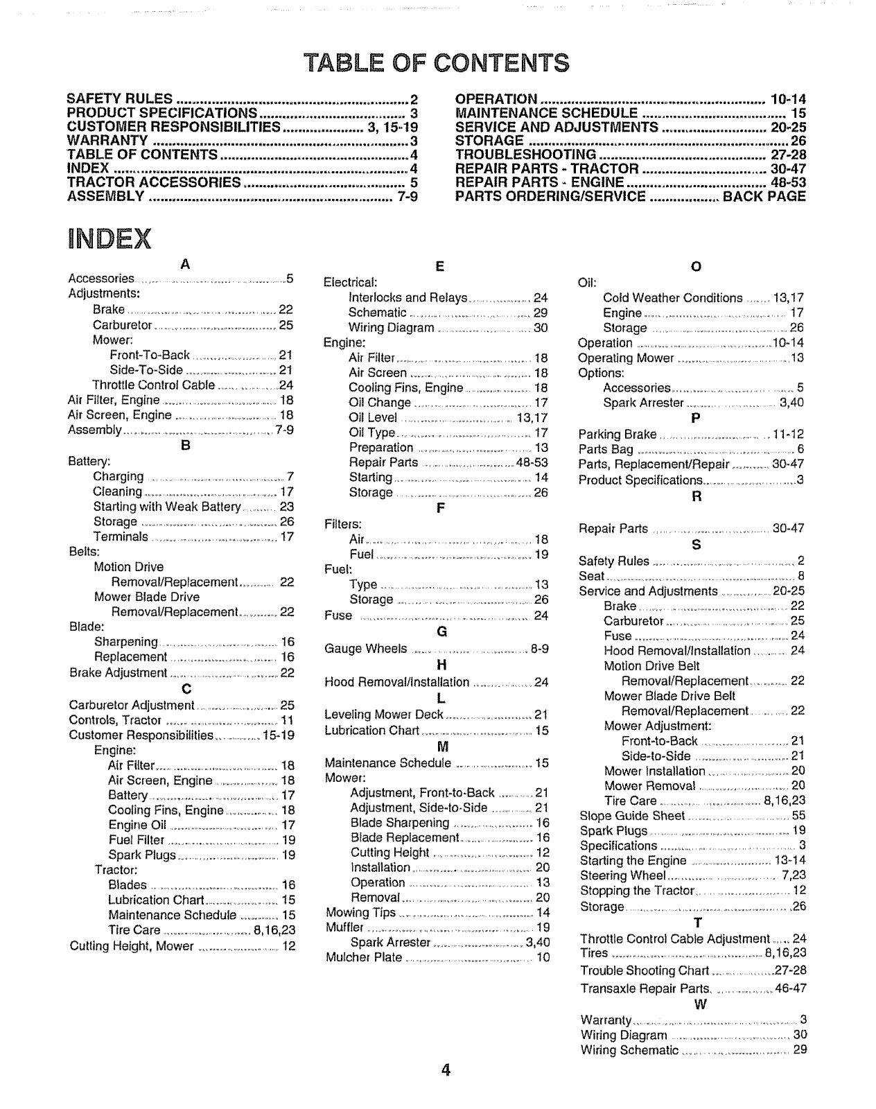
Craftsman 917.25254 User manual

Category
Lawnmowers
Type
User manual

This manual is also suitable for

_9
®
MODEL 917.252540
° Assembly
° Operation
o Customer Responsibilities
oService and Adjustments
o Repair Parts
OWNER'S MANUAL
Convertible
CAUTION: Read and follow all safety rules and instructions before operating this equipment.
FOR CONSUMER ASSISTANCE HOT LINE, CALL THIS TOLL FREE NUMBER: 1-800-659-5917
SAFETY RULES
Safe Operation Practices for Ride-On Mowers
IMPORTANT: THIS CUTTING MACHINE IS CAPABLE OF AMPUTATING HANDS AND FEET AND THROWING OBJECTS
FAILURE TO OBSERVE THE FOLLOWING SAFETY INSTRUCTIONS COULD RESULT IN SERIOUS INJURY OR DEATH.
1. GENERAL OPERATION
Read, understand, and follow al! instructions in the manual
and on the machine before starting
- Only allow responsible adults, who are familiar with the
instructions, to operate the machine.
Clear the area of objects such as rocks, toys, wire, etc,
which could be picked up and thrown by the blade.
Be sure the area is clear of other people before mowing, Stop
machine if anyone enters the area°
Never carry passengers.
Do not mow in reverse unless absolutely necessary. Always
look down and behind before and while backing.
Be aware of the mower discharge direction and do not point
it at anyone. Do not operate the mower without either the
entire grass catcher or the guard in place.,
Slow down before turning
Never leave a running machine unattended. Always turn off
blades, set parking brake, stop engine, and remove keys
before dismounting.
° Turn off blades when not mowing.
Stop engine before removing grass catcher or' unclogging
chute°
° Mow only in daylight or good artificial light..
° Do not operate the machine while under the influence of
alcohol or drugs,_
Watch for traffic when operating near or crossing roadways.,
Use extra care when loading or' unloading the machine into
a trailer or truck.,
II. SLOPE OPERATION
Slopes are a major' factor related to loss-of-control and
tipover accidents, which can result in severe injury or death.
All slopes require extra caution. If you cannot back up the
slope or if you feel uneasy on it, do not mow it.
DO:
. Mow up and down slopes, not across.
° Remove obstacles such as rocks, tree limbs, etc.
o Watch for holes, ruts, or bumps_ Uneven terrain could
overturn the machine° Tall grass can hide obstactes_
o Use s_owspeed. Choose a low gear so that you will not have
to stop or shift while on the slope.
o Follow the manufacturer's recommendations for wheel
weights or counterweights to improve stability
o Use extra care with grass catchers or other attachments.
These can change the stability of the machine,
o Keep all movement on the slopes slowand gradual, Do not
make sudden changes in speed or direction
o Avoid starting or stopping on a slope, ff tires lose traction,
disengage the blades and proceed slowly straight down the
slope,
DO NOT:
. Do not turn on slopes unless necessary, and then, turn slowly
and gradually downhill, if possible
o Do not mow near drop-offs, ditches, or embankments. The
mower could suddenly turn over if a wheel is over the edge
of a cliff or ditch, or if an edge caves in.
o Do not mow on wet grass.. Reduced traction could cause
sliding.,
. Do not try to stabilize the machine by putting your foot on the
ground_
o Do not use grass catcher on steep slopes.
2
III. CHILDREN
Tragic accidents can occur ifthe operator is not alert to the
presence of children. Children are often attracted to the
machine and the mowing activity_ Never assume that
children will remain where you last saw them.,
Keep children out of the mowing area and under the watchful
care of another responsible adult,
Be alert and turn machine off if children enter the area.
° Before and when backing, look behind and down for small
children.
Never carry children. They may fall off and be seriously
injured or interfere with safe machine operation.
Never allow children to operate the machine.
Use extra care when approaching blind corners, shrubs,
trees, or other objects that may obscure vision,
IV. SERVICE
Use extra care in handling gasoline and other fuels They are
flammable and vapors are explosive
- Use only an approved container.
Never remove gas cap or add fuel with the engine
running_ Allow engine to cool before refueling Do not
smoke..
- Never refuel the machine indoors.
Never store the machine or fuel container inside where
there is an open flame, such as a water heater.
Never run a machine inside a closed area
Keep nuts and bolts, especially blade attachment bolls, tight
and keep equipment in good condition..
° Never tamper with safety devices.. Check their proper
operation regularly
Keep machine free of grass, leaves, or other debris build-upo
Clean oil or fuel spillage, Allow machine to coo! before
storing_
Stop and inspect the equipment if you strike an object.
Repair, if necessary, before restarting
Never make adjustments or repairs with the engine running
Grass catcher components are subject to wear, damage, and
deterioration, which could expose moving parts or allow
objects to be thrown. Frequently check components and
replace with manufacturer's recommended pads, when nec-
essary.
Mower blades are sharp and can cut. Wrap the blade(s) or
wear gloves, and use extra caution when servicing them.
Check brake operation frequently. Adjust and service as
required..
................ Look for thi's'""symboi"to poi'nt out iT-
portant safety precautions. It means
CAUTIONt!! BECOME ALERT!!! YOUR
SAFETY IS INVOLVED.
.... CAUTION: Always disconnect spark plug I
_ wireandplacewirewhereitcannotcontact I
spark plug in order to prevent accidental I
starting when setting up, transporting, |
adjusting or making repairs. .........
& WARNING
The engine exhaust from this product con-
tains chemicals known to the State of Califor-
nia to cause cancer, birth defects, or other
reproductive harm.
CONGRATULATIONS on your purchase of a Sears
Tractor. It has been designed, engineered and manufac-
tured to give you the best possible dependability and
performance.
Should you experience any problem you cannot easily
remedy, please contact your nearest Sears Authorized
Service CentedDepartment. We have competent, well-
trained technicians and the proper tools to service or repair
this tractor.
Please read and retain this manual.. The instructions will
enable you to assemble and maintain your tractor properly.
Always observe the "SAFETY RULES'L
MODEL
NUMBER 917252540
SERIAL
NUMBER
DATE OF PURCHASE
THE MODEL AND SERIAL NUMBERS WILL BE FOUND
ON A PLATE UNDER THE SEAT°
YOU SHOULD RECORD BOTH SERIAL NUMBER AND
DATE OF PURCHASE AND KEEP tN A SAFE PLACE
FOR FUTURE REFERENCE°
MAINTENANCE AGREEMENT
A Sears Maintenance Agreement is available on this prod-
UCto Contact your nearest Sears store for detaits_
CUSTOMER RESPONSIBILITIES
o Read and observe the safety rules.
° Fo!low a regular schedule in maintaining, caring for and
using your tractor.
° Fotlow the instructions under "Customer Responsibili-
ties" and "Storage" sections of this owner's manual
PRODUCT SPECRFICATIONS
HORSEPOWER: 14.5
GASOLINE CAPACITY 5 QUARTS
AND TYPE: UNLEADED REGULAR
OIL TYPE (API-SF/SG): SAE 10W30 (above 32°F)
SAE 5W-30 (below 32°F)
OIL CAPACITY: W/FILTER: 4.0 PINTS
W/O FILTER: 3.5 PINTS
SPARK PLUG: CHAMPION RC12YC
(GAP: .040")
VALVE CLEARANCE: NOT ADJUSTABLE
GROUND SPEED (MPH): FORWARD:
1st 1,1
2nd 1.4
3rd 2_0
4th 3.0
5th 42
6th 5..0
REVERSE: 15
TIRE PRESSURE: FRONT: 14 PSI
REAR: 10 PSI
CHARGING SYSTEM: 3 AMPS BATTERY
5 AMPS HEADLIGHTS
BLADE BOLT TORQUE: 30_35 FT, LBS.
WARNING: This tractor is equipped with an internal
combustion engine and should not be used on or near any
unimproved forest-covered, brush-covered or grass-cov-
ered land unless the engine's exhaust system is equipped
with a spark arrester meeting applicable local or state laws
(if any). If a spark arrester is used, itshould be maintained
in effective working order by the operator..
In the state of California the above is required by law
(Section 4442 of the California Public Resources Code)_
Other states may have similar laws. Federal laws apply on
federal lands. A spark arrester for the muffler is available
through your nearest Sears Authorized Service Center/
Department (See REPAIR PARTS section of this manual).
.......... i H iH.-...:_... illl¸ ,
LiMiTED TWO YEAR WARRANTY ON CRAFTSMAN RIDING EQUIPMENT
For two (2) years from the date of purchase, if this Craftsman Riding Equipment is maintained, lubricated and tuned up according
to the instructions in the owner's manual, Sears will repair or replace, free of charge, any pads found to be defective in material
or workmanship,
This Warranty does not cover:
Expendable items which become worn during normal use, such as blades, spark plugs, air cleaners, belts, elc
Tire replacement or repair caused by punctures from outside objects, such as nails, thorns, stumps, or glass.
Repairs necessary because of operator abuse, negligence, improper storage or accident or the failure to maintain the
equipment according to the instructions contained in the owner's manual
Riding equipment used for commercial or rental purposes
LIMITED 90 DAY WARRANTY ON BATTERY
For ninety (90) days from date of purchase, if any batter,] included with this riding equipment proves defective in material or
workmanship and our testing determines the battery will not hold a charge, Sears will replace the battery at no charge.
IN-HOME WARRANTY SERVICE ON YOUR CRAFTSMAN RIDING EQUIPMENT IS AVAILABLE AT NO-CHARGE FOR 30
DAYS FROM THE DATE OF PURCHASE. PLEASE CONTACT YOUR NEAREST SERVICE CENTER.. AFTER 30 DAYS
FROM THE DATE OF PURCHASE, WARRANTY SERVICE IS AVAILABLE BY TAKING YOUR CRAFTSMAN RIDING EQUIP-
MENT TO YOUR NEAREST SEARS SERVICE CENTER_ (IN-HOME WARRANTY SERVICE WILL STILL BE AVAILABLE
AFTER 30 DAYS FROM THE DATE OF PURCHASE BUT A STANDARD TRIP CHARGE WILL APPLY.) THiS WARRANTY
APPLIES ONLY WHILE THIS PRODUCT IS IN THE UNITED STATES ......
This Warranty gives you specific legal rights, and you may also have other rights which may vary from state to state.
HOFFMAN ESTATES, IL 60179SEARS, ROEBUCK AND CO., D/817 WA,, ,
i1, ,. i ,i.i 'II'H ' I I'WlIII'II, ,I ' III ''llw,l:lll,
3
TABLE OF CONTENTS
SAFETY RULES ............................................................ 2
PRODUCT SPECIFICATIONS ...................................... 3
CUSTOMER RESPONSIBILITIES ..................... 3, 15-19
WARRANTY .................................................................. 3
TABLE OF CONTENTS ................................................. 4
INDEX ............................................................................ 4
TRACTOR ACCESSORIES .......................................... 5
ASSEMBLY ............................................................... 7-9
OPERATION .......................................................... 10-14
MAINTENANCE SCHEDULE ..................................... 15
SERVICE AND ADJUSTMENTS ........................... 20-25
STORAG E ................................................................... 26
TROUBLESHOOTING ........................................... 27-28
REPAIR PARTS - TRACTOR ................................ 30-47
REPAIR PARTS - ENGINE .................................... 48-53
PARTS ORDERING/SERVICE .................. BACK PAGE
INDEX
A
Accessories ...............................................................5
Adjustments:
Brake ..............................................................22
Carburetor ....................................................25
Mower:
Front-To-Back ..............................21
Side-To-Side ......................................2!
Throttle Control Cable ........................24
Air Filter, Engine ..............................................18
Air Screen, Engine ..........................................18
Assembly .......................................................7-9
B
Battery:
Charging ......................................................7
Cleaning .....................................................17
Starting with Weak Batten,/ ............23
Storage ..................................................26
Terminals ............................................17
Belts:
Motion Drive
Removal/Replacement ...............22
Mower Blade Drive
Removal/Replacement ...............22
Blade:
Sharpening ............................................t6
Replacement .......................................16
Brake Adjustment ........................................22
C
Carburetor Adjustment .................................25
Controls, Tractor, .......................................11
Customer Responsibilities ..................15-19
Engine:
Air Filter ..........................................18
Air Screen, Engine .........................18
Battery ..............................................17
Cooling Fins, Engine ....................18
EngineOil..............................................17
Fuel Filter,..........................................19
Spark Plugs ......................................19
Tractor:
Blades .................................................16
Lubrication Chad ..............................15
Maintenance Schedule ................15
Tire Care ...................................8,16,23
Cutting Height, Mower .................................12
E
Electrical:
Interlocks and Relays .........................24
Schematic ........................................29
Wiring Diagram .....................................30
Engine:
Air Filter ........................................................18
Air Screen ............................................18
Cooling Fins, Engine ...........................18
Oil Change .............................................17
Oil Level ..........................................13,17
Oit Type ................................................17
Preparation .............................................13
Repair Parts ........................................48-53
Stading ................................................14
Storage ................................................26
F
Fitters:
Air.........................................................18
Fuel ...............................................................19
Fuel:
Type ...............................................................t3
Storage .....................................................26
Fuse ..............................................................24
G
Gauge Wheels ........................................8-9
H
Hood Removalttnstallation ....................24
L
Leveling Mower Deck ..................................21
Lubrication Chad .............................................15
M
Maintenance Schedule ...............................15
Mower:
Adjustment, Front4o-Back ..............21
Adjustment, Side-to-Side ...............2t
Blade Sharpening ..................................16
Blade Replacement ............................16
Cutting Height .....................................12
Installation ..............................................20
Operation ................................................13
Removal .................................................20
Mowing Tips ....................................................14
Muffler ..........................................................i9
Spark Arrestor ..............................3,40
Mulcher Plate .............................................10
4
0
Oil:
Cold Weather Conditions ....... 13,17
Engine ...........................................................17
Storage ............................................................26
Operation .................................................10-14
Operating Mower ..............................................13
Options:
Accessories .................................................5
Spark Arrestor, ............................. 3,40
P
Parking Brake .............................................11-12
Parts Bag ..............................................................6
Parts, Replacement/Repair ..............30-47
Product Specifications .................................3
R
Repair Pads ..........................................30-47
S
Safety Rules ...............................................2
Seat ..................................................................................8
Service and Adjustments .....................20-25
Brake ..........................................................22
Carburetor ...............................................25
Fuse ................................................................24
Hood Removal/Installation ...............24
Motion Ddve Belt
Removal/Replacement ...................22
Mower Blade Drive Belt
Remova!/Replacement ..............22
Mower Adjustment:
Front-to-Back ................................21
Side-to-Side ....................................21
Mower Installation ..............................20
Mower Removal .......................................20
Tire Care ........................................8,16,23
Slope Guide Sheet ....................................55
Spark Plugs ..........................................................19
Specifications ......................................................3
Starling the Engine ...............................13-14
Steering Wheel .....................................7,23
Stopping the Tractor ...................................t2
Storage ..............................................................26
T
Throttle Control Cable Adjustment .......24
Tires .........................................................8,16,23
Trouble Shooting Chad .......................27-28
Transaxle Repair Pads .....................46-47
W
Warranty .............:..................................................3
Wiring Diagram ............................................30
Wiring Schematic .......................................29
ACCESSORIES A ATTACH ENTS
........ i i ...... i i l i, ,l i,,
These accessories and attachments were available through most Sears retail outlets and service centers when the tractor was purchased_
Most Sears stores can order these items for you when you provide the model number of your tractor,
ENGINE
SPARK PLUG GAS CAN ENGtNE OIL FUEL STABILIZER AIR FILTER
MAINTENANCE
BLADES BELTS
PERFORMANCE
Sears offers a wide variety of attachments that fit your tractor_ Many of these are listed below with brief explanations of how they can help
you. This list was current at the time of publication; however, it may change in future years _ more attachments may be added, changes
may be made in these attachments, or some may no longer be available or fit your modet. Contact your nearest Sears store for the
accessories and attachments that are available for your tractor.
Most of these attachments do not require additional hitches or conversion kits (those that do are indicated) and are designed for easy
attaching and detaching°
AERATOR promotes deep root growth for a healthy lawn. Ta-
pered 25-inch steel spikes mounted on 10-inch diameter discs
puncture holes in soi_at close intervals to let moisture soak in.
Steel weight tray for increased penetration
BAGGER lets you collect grass clippings and leaves for a
healthier, neater looking lawn. Two Permanex containers hold
30-gallon plastic bags.
BUMPER protects front end of tractor from damage
CARTS make hauling easy Variety of sizes available, plus
accessories such as side panel kits, tool caddy, cart cover,
protective mat and dolly.
CORING AERATOR takes small plugs out of soil to allow mois-
ture and nutrients to reach grass roots, 36-inch swath 24
hardened steel coring tips 150 lb. capacity weight tray.
EASY OIL DRAIN VALVE makes oil changes easier, faster,
FRONT NOSE ROLLER canters in front of mower deck to reduce
chances of "scalping" on uneven terrain..
GANG HITCH lets you tow 2or 3 pull-behind attachments at once,
such as sweepers, dethatchers, aerators (not for use with rollers,
carts or other heavy attachments),
GAUGE WHEELS on both sides of the mower deck reduce
chances of "scalping" on uneven terrain, For mower decks not so
equipped.
MULCH RAKE/DETHATCHER loosens soil and flips thatch and
matted leaves to lawn surface for easy pickup. Twenty spring tine
teeth. Useful topreparebareareasforseeding. Availableforfront
or rear mounting. HIGH PERFORMANCE REEL-ACTION
SPRING TINE DETHATCHER covers 36-inch wide path and
tosses thatch into large hopper. Mounts behind tractor.
MULCHING CLOSE-OUT PLATE KIT, once installed, lets you
mulch, discharge or bag clippings (bagger optional) without
changing blades.. For models not equipped as 3-in-1 Convertible
mowers° See "MOWER" in the Repair Parts section of this
manual,
RAMP TOPS AND FEET let you load and unload tractor from a
pickup truck_ Use with 2 x 8 or 2 x 10 lumber..
ROLLER for smoother lawn surface. 36-inch wide, 18*inch
diameterwater-tight drum holds upto 390 lbs.ofweight. Rounded
edges prevent harm to turf,. Adjustable scraper automatically
cleans drum
SNOW BLADE for snow removal only. 14-inch high, 48-inch wide
blade clears42-inch path when angled felt or right. Raises, lowers
with side lever Adjustable skids; replaceable, reversible scraper
bar.. (Use with tire chains and wheel weights and/or rear drawbar
weight.)
SNOWTHROWER has 40-inch swath. Drum-type auger handles
powdery and wet/heavy snow., Mounts easily with simple pin
arrangement° Discharge chute adjusts from tractor seat.. 6-inch
diameter spout discharges snow 10 to 50 feet Lift controlled at
tractor seat. (Use with chains and wheel weights and!or rear
drawbar weight..)
SPRAYERS use 12-voft DC electric motor that connects to the
tractor battery or other 12-volt source. Includes booms for
automatic spraying and hand held wand for spot spraying.. Wand
has adjustable spray pattern For applying herbicides, insecti-
cides, fungicides and liquid fertilizers,
SPREADER/SEEDERS make seeding, fertilizing, and weed kill-
ing easy. Broadcast spreaders are also useful for granular de-
icers and sand.
SWEEPERS let you collect grass clippings and leaves,
TILLER has 5hp engine and 36-inch swath to prepare seed beds,
cultivate and compost garden residue. Tiller has its own built-in
tift and depth control system and does NOT require asleeve hitch.
Fits any lawn, yard or garden tractor Simply hook up to the tractor
drawbar and go! Optional accessories convert unit for
dethatching, aerating, hilling.., _without tools.
TIRE CHAINS are heavy duty; closely spaced extra-large cross
links give smooth ride, outstanding traction
TRACTOR CAB has heavy duty vinyl fabric over tubular steel
frame, ABS plastic top; clear plastic windshield offers 360 degree
visibility. Hinged metal doors with catch. Keeps operator warm
and dry, Remove vinyl sides and windshierds for use as sun
protector in summer. Optional accessories include: tinted/
tempered solid safety glass windshield with hand operated wiper;
12-volt amber caution light for mounting on cab top
VACS for powerful collection of heavy grass clippings and leaves.
Optional wand attachment to pick up debris in hard-to-reach
places. VAC/CHIPPER includes a chipper-shredder.
WEIGHT BRACKET for drawbar for snow removal applications
Uses (1) 55 lb. weight.
WHEEL WEIGHTS for rear wheels provide needed traction for
snow removal or dozing heavy materials
5
CONTENTS
,,inn,H ..........
OF HARDWARE
PACK
i
Parts Bag contents shown full size
O (2) Sheet
Metal
Screws
#10-16 x 1/42
(1) Large Flat Washer
(-
(!) Shoulder Bolt 5t16-18
(1) Hex Bolt 1/2-13 x 1
(1) Lock Washer 1/2
(!) Washer" 17/32 x 1-3116 x 12 Gauge
(2) Screws #10 x 5/8 (2) Lock Washers #10
O (2) Weld Nuts #10 i
ashers 3/16 x 3/4 x 16 Gauge _"
(2) Hex Bolts 114-20 x 314
(2) Hex Nuts 1/4-20
[2) Washers 9/32 x 5/8 x 16 Gauge
(2) Lock Washers !/4
Parts packed separately in carton
Steering
Wheel
Manual
Video
Cassette
Steering
Boot
Il
t
Parts Bag
....... IIIIIIIII_IIIIIIUIII_U 11 jLjjj
Parts bag contents not shown full size
n i, ii , ii ...................................
(2) Shoulder
Bolts
Steering Wheel
Adapter
_ok
Assemblys
(2) Washers 3/8
x 7/8 x 14 Gauge
Gauge _ (2) Center-
lock Nuts
(_ Steedng
Bushing
(2) Keys
Slope Sheet
i,, ill , .......................
Steering
Wheel
Insert
U LJ
6
LY
i iill Ill. I / I / / I Illllll III,
Your new tractor has been assembled at the factory with exception of those parts left unassembled for shipping purposes.
To ensure safe and proper operation of your tractor all parts and hardware you assemble must be tightened securely. Use
the correct tools as necessary to insure proper tightness°
TOOLS REQUIRED FOR ASSEMBLY
A socket wrench set will make assembly easier.. Standard
wrench sizes are listed_
(1) 5/16" wrench
(2) 7/16" wrenches
(1) 1/2" wrench
(1) 9/16" wrench
(1) 3/4" Socket w/drive rachet
Phillips Screwdriver
Tire pressure gauge
Utility knife
When right or left hand is mentioned in this manual, it
means when you are in the operating position (seated
behind the steering wheel).
TO REMOVE TRACTOR FROM CARTON
UNPACKCARTON
Remove all accessible loose parts and parts cartons
from carton (See page 6).
. Cut, from top to bottom, along lines on all four corners
of carton, and lay panels flat..
° Check for any additional loose parts or cartons and
remove,
BEFORE ROLLING TRACTOR OFF SKaD
ATTACH STEERING WHEEL (See Fig, 1)
o Slide the steering bushing over the steering shaft°
° Raise steering shaft forward until screw holes in dash
line up with steering bushing, Install two (2) sheet
metal screws and tighten securely°
Position steering boot over steering shaft
. Place tabs of steering boot over tab slots in dash and
push down to secure.
° Slide steering wheel adapter onto upper stee ring shaft.
- Position front wheels of the tractor so they are pointing
straight forward°
o Position steering wheel so cross bars are horizontal
(left to right) and slide onto adapter_
= Assemble large flat washer and 3/8-24 iocknut and
tighten securely.
° Snap steering wheel insert into center of steering
wheel.
= Remove protective plastic from tractor hood and grill..
IMPORTANT:CHECK FOR AND REMOVE ANY STAPLES
IN SKiD THAT MAY PUNCTURE TIRES WHERE TRACTOR
tS TO ROLL OFF SKiD
TO ROLL TRACTOR OFF SKID (See Fig. 8)
Raise attachment lift lever to its highest position°
° Release parking brake by depressing clutch/brake
pedal
o Place gearshift lever in neutral (N) position.
° Roll tractor backwards off skid,,
Remove banding holding discharge guard up against
tractor,
STEERING
_ WHEEL INSERT
.... 3t8-24 LOCKNUT
_ LARGE FLAT
WASHER
STEERING
STEERING
)_ WHEEL
STEERING
I BUSHING
SCREW
TABS
STEERING _ A
,oo
STEERING _ //
SHAFT _ TAB
HOLE
POSITION)
STEERING
SHAFT
(SHIPPING
POSITION)
FIG. 1
7
CONNECT BATTERY (See Figs. 2 and 3)
CAUTION: Do not short battery termio
_ nals. Before connecting battery, re-
move metal bracelets, wristwatch
bands, rings, etco
Positive terminal must be connected
first to prevent sparking from acciden-
tal grounding.
Remove cardboard packing from seat pan and lift seat
pan to raised position,.
° Open battery box door.
o Remove terminal protective caps and discard.
o If this battery is put into service after month and year
indicated on label (label located between terminals)
charge battery for minimum of one hour at 6-10 amps.
° First connect RED battery cable to positive (+) terminal
with hex bolt, flat washer, lock washer and hex nut as
shown° Tighten securely..
° Connect BLACK grounding cable to negative (-) termi-
nal with remaining hex bolt, fiat washer, lock washer
and hex nut° Tighten securely.
° Close battery box door
Openbatteryboxdoorfor:
o
o
o
e
ASSEMBLY
Inspection for secure connections (to tighten hard-
ware),,
Inspection for corrosion_
Testing battery,
Jumping (if required)_
Periodic charging ,.
POSITIVE
(RED) CABLE
DISCARD
TERMINAL
PROTECTIVE
CAPS
_, HEX
NUT
LOCK
WASHER
FLAT
WASHER
VENT
HOLE
(KEEP
CLEAN)
BOLT
NEGATIVE
(BLACK) CABLE
FIG. 2
SEA"['
PAN
BATTERY
BOXDOOR
FIG, 3
SEAT PAN
SEAT
,\
LOCK WASHER
ADJUSTMENT LARGE FLAT WASHER
BOLT
FIG. 4
CHECK TIRE PRESSURE
The tires on your tractor were overinflated at the factory for
shipping purposes, Correct tire pressure is important for
best cutting performance,.
o Reduce tire pressure to PS! shown in "PRODUCT
SPECIFICATIONS" on page 3 of this manual
CHECK DECK LEVELNESS
Forbest cutting results, mower housing should be propedy
leveled. See "TO LEVEL MOWER HOUSING" in the
Service and Adjustments section of this manual,
CHECK FOR PROPER POSITION OF ALL
BELTS
See the figures that are shown for replacing motion and
mower blade drive belts in the Service and Adjustments
section of this manual_ Verify that the belts are routed
correctty._
CHECK BRAKE SYSTEM
After you learn how to operate your tractor, check to see
that the brake is properly adjusted1. See "TO ADJUST
BRAKE" in the Service and Adjustments section of this
rnanuat.
INSTALL SEAT (See Fig. 4)
Adjust seat before tightening adjustment bolt.,
Remove cardboard packing on seat pan..
o Place seat on seat pan and assemble shoulder bolt,
Assemble adjustment bolt, lock washer and flat washer
loosely, Do not tighten°
Tighten shoulder bolt securely,
° Lower seat into operating position and sit on seat°
o Slide seat until a comfortable position is reached which
allows you to press clutch/brake pedal all the way
down°
° Get off seat without moving its adjusted position..
o Raise seat and tighten adjustment bolt securely.
ASSEMBLE GAUGE WHEELS TO MOWER
DECK (See Fig. 5)
Assemble gauge wheels with tractor on a fiat level surface,
o Adjust mower to desired cutting height (See "TO AD-
JUST MOWER CUTTING HEIGHT" in the Operation
section of this manual),,
° With mower in desired height of cut position, gauge
wheels should be assembled so they are slightly off the
ground, Install gauge wheel in appropriate hole with
shoulder bolt, 3/8 washer and 3/8-I6 Iocknut and
tighten securefy,
° Repeat for opposite side installing gauge wheel in
same adjustment hole.
8
ASSE LY
GAUGE WHEEL
MOUNTING
BRACKET
318-16.-_'_
LOCKNUT
318" WASHER
GAUGE WHEEL
_,,/.SHOULDER BOLT
FIG, 5
INSTALL MULCHER PLATE
(See Figs, 6 and 7 )
o install two latch hooks to mulcher plate using screw,
washer, lock washer, and weld nut as shown..
NOTE: Pre-assemble weld nut to latch hook by inserting
weld nut from the top with hook pointing down_
Tighten hardware securely..
. Raise and hold deflector shield in upright position.
° Place front of mulcher plate over front of mower deck
opening and slide into place, as shown_
. Hook front latch into hole on front of mower deck.
° Hook rear latch into hole on back of mower deck°
CAUTION: Do not remove discharge
guard from mower. Raise and hold
guard when attaching mulcher plate
and allow it to rest on plate while in
operation.
WELD NUT FROM THE TOP HOOK POINTS DOWN
LOCK
WELD WASHER
NUT ,.\\\\ SCREW
t.ATCH _
LATCH
HOOK
WASHER
MULCHER
PLATE
LOCK
WASHER
WASHER
_SCREW
FIG. 6
WELD
NUT
DEFLECTOR
SHIELD
FIG. 7
LATCH
HOOKS
TO CONVERT TO BAGGING OR
DISCHARGING
Simply remove mulcher plate and store in a safe place.
Your mower is now ready for discharging or installation of
optional grass catcher accessory.
,/CHECKLIST
BEFORE YOU OPERATE AND ENJOY YOUR NEW
TRACTOR, WE WISH TO ASSURE THAT YOU RECEIVE
THE BEST PERFORMANCE AND SATISFACTION FROM
THIS QUALITY PRODUCT
PLEASE REVIEW THE FOLLOWING CHECKLIST:
,/ Al! assembly instructionshave been completed..
v" No remaining loose parts in carton°
v" Batteryis property prepared and charged (Minimum
1 hour at 6 amps).
v" Seat is adjusted comfortably and tightened securely.
,/ All tires are properly inflated. (For shipping purposes,
the tires were overinflated at the factory).
v" Be sure mower deck is properly leveled side-to-sidel
front-to-rear for best cutting results. (Tires must be
properly inflated for leveling)
,/ Check mower and drive belts. Be sure they are routed
properly around pulleys and inside all belt keepers,
,/ Check wiring. See that all connections are still secure
and wires are properly clamped_
WHILELEARNING HOWTO USE YOUR TRACTOR, PAY
EXTRA A 7TENTION TO THE FOLLOWING IMPORTANT
ITEMS:
¢' Engine oil is at proper level..
¢" Fuel tank is filled with fresh, clean, regular unleaded
gasoline.
¢" Become familiar with all controls - their location and
function. Operate them before you start the engine.
,/ Be sure brake system is in safe operating condition.
9
......... : :::::1111i i ii i ii
OPERATmON
These symbols may appear on your tractor or in literature supplied with the product, Learn and understand their meaning.
BATTERY CAUTION OR SLOW
WARNING
ENGfNE ON ENGINE OFF LIGHTS OFF
REVERSE FORWARD FAST
d)-
OIL PRESSURE CLUTCH LIGHTS ON
FUEL UNLOCKED
X
CHOKE MOWER HEIGHT DIFFERENTIAL PARKING BRAKE
LOCK LOCKED
MOWER LIFT
REVERSE NEUTRAL HIGH LOW
ATTACHMENT
CLUTCH ENGAGED
÷
ATTACHMENT
CLUTCH DISENGAGED
PARKING BRAKE
IGNITION
DANGER, KEEP HANDS AND FEET AWAY
HYDROSTATIC FREE WHEEL
(Hydro Models only)
10
OPERATION
,..ill ,i ii ,ll ii i i
KNOW YOUR TRACTOR
READ THIS OWNER'S MANUAL AND SAFETY RULES BEFORE OPERATING YOUR TRACTOR
Comparethe illustrations withyourtractor to familiarize yourself with the locations of various controls and adjustments, Save
this manual for future reference°
THROTTLE/CHOKE
CONTROL
CLUTCHIBRAKE
PEDAL
HEIGHT
ADJUSTMENT
KNOB
AMMETER
I\1
IGNITION LIFT LEVER PLUNGER
SWITCH
/
ATTACHMENT
ATTACHMENT
LEVER
PARKING BRAKE
GEARSHIFT
LEVER
FIG. 8
Our tractors conform to the safety standards of the American National Standards Institute_
ATTACHMENT CLUTCFt LEVER: Used to engage the
mower blades, or other attachments mounted to your
tractor_
LIGHT SWITCH: Turns the headlights on and off.
THROTTLE/CHOKE CONTROL: Used for starting and
controlling engine speed°
CLUTCHtBRAKE PEDAL: Used for declutching and brak-
ing the tractor and starting the engine°
PARKING BRAKE: Locks clutch/brake pedal into the
brake position°
I
GEARSHIFT L.EVER: Selects the speed and direction o_
tractor, i
ATTACHMENT LIFT LEVER: Used to raise and lower the
mower deck or other attachments mounted to your tractor,
LIFT LEVER PLUNGER: Used to release attachment lift
lever when changing its position,,
IGNITION SWITCH: Used for starting and stopping the
engine.
HEIGHTADJUSTMENT KNOB; Used to adjust the mower
cutting height.
AMMETER: Indicates battery charging (+) or discharging
11
OPERAT OIN
The operation of any tractor can result in foreign objects thrown into the eyes, which can
result in severe eye damage. Always wear safety glasses or eye shields while operating your
tractor or performing any adjustments or repairs. We recommend a wide vision safety mask
over the spectacles or standard safety glasses.
HOW TO USE YOUR TRACTOR
TO SET PARKING BRAKE (See Fig. 9)
Your tractoris equipped with an operator presence sensing
switch. When engine is running, any attempt by the
operator to leave the seat without first setting the parking
brake will shut off the engine.
° Depress clutch/brake pedal intofull "BRAKE" position
and hotd_
Place parking brake lever in "ENGAGED" position and
release pressure from clutch/brake pedal.. Pedal should
remain in "BRAKE" position.. Make sure parking brake
will hold tractor secure.
THROTTLE/
CHOKE
CONTROL
ATTACHMENT CLUTCH LEVER
"ENGAGED" POSITION
"DISENGAGED"
POSITION
"BRAKE"
POSITION
PARKING BRAKE
!'ENGAGED" POSITION
GEARSHIFT
LEVER
CLUTCHIBRAKE PEDAL
"DRIVE" POSITION
"DISENGAGED"
POSITION
HEIGHT ADJUSTMENT KNOB
FIG. 9
STOPPING (See Fig. 9)
MOWER BLADES -
° Move attachment clutch lever to "DISENGAGED" po-
sitiono
GROUND DRIVE -
o Depress clutch/brake pedal into full "BRAKE" position.
= Move gearshift lever to neutral (N) position.
ENGINE -
Move throttle control to slow (_,) position.
NOTE: Failure to move throttle control to slow (°_,)
position and allowing engine to idle before stopping may
cause engine to "backfire".
° Turn ignition key to "OFF" position and remove key.
Always remove key when leaving tractor to prevent
unauthorized use.
= Never use choke to stop engine.
NOTE: Under certain conditions when tractor is standing
idle with the engine running, hot engine exhaust gases may
cause "browning" of grass. To eliminate this possibility,
always stop engine when stopping tractor on grass area&
CAUTION: Always stop tractor com-
pletely, as described above, before leav-
ing the operator's position; to empty
grass catcher, etc.
TO USE T!tROTTLE CONTROL (See Fig. 9)
Always operate engine at full throttle
o Operating engine at less than full throttle reduces the
battery charging rate..
= Full throttle offers the best bagging and mower perfor-
mance.
TO MOVE FORWARD AND BACKWARD
(See Fig, 9)
The direction and speed of movement is controlled by the
gearshift lever.
o Start tractor wit'h clutch/brake pedal depressed and
gearshift lever in neutral (N) position.,
. Move gearshift and range shift levers to desired posi-
tion.
o Slowly release clutch/brake pedal to start movemenL
IMPORTANT; BRING TRACTOR TO A COMPLETE STOP
BEFORE SHIFTING OR CHANGING GEARS. FAILURE
TO DO SO WILL SHORTEN THE USEFUL LIFE OF YOUR
TRANSAXLE
TO ADJUST MOWER CUTTING HEIGHT
(See Fig. 9)
The cutting height iscontrolled by turning the height adjust-
ment knob in desired direction..
o Turn knob clockwise (f'-_) to raise cutting height.
° Turn knob counterclockwise (_p-_) to lower'cutting
height,
The cutting height range is approximately 1-1/2" to 4L The
heights are measured from the ground to the blade tip with
the engine not running., These heights are approximate
and may vary depending upon soil conditions, height of
grass and types of grass being mowed
The average lawn should be cut to approximately 2-1/2
inches during the cool season and to over 3 inches
during hot months. For healthier and better looking
lawns, mew often and after moderate growth,
= For best cutting performance, .grass over6 inches in
height should be mewed twice., Make the first cut
relatively high; the second to desired heighL
12
OPEF AT ON
TO OPERATE MOWER (See Fig. 10)
Your tractor isequipped with an operator presence sens-
ing switch.. Any attempt by the operator to leave the seat
with the engine runnJngand the attachment clutch engaged
will shut off the engine°
Select desired height of cut
Lower mower with attachment lift control
o
o
Start mower blades by engaging attachment clutch
control
TO STOP MOWER BLADES - disengage attachment
clutch control°
, illll ,IL,i,l,ll, ,ll,,iJll,,i ii i, i , i1,1, i
CAUTION: Do not operate the mower
without either the entire grass catcher,
on mowers so equipped, or the dis-
charge guard in place.
ATTACHMENT CLUTCH LEVER
"DISENGAGED" POSITION
"ENGAGED"
POSITION
ATTACHMENT
HIGH POSITION
FIG, 10
DISCHARGE
GUARD
TO OPERATE ON HILLS
CAUTION: Do not drive up or down
hills with slopes greater than 15° and
do not drive across any slope.
Choose the slowest speed before starting up or down
hills,
Avoid stopping or changing speed on hills.
o If slowing is necessary, move throttle control lever to
slower position.
° If stopping is absolutely necessary, push clutch/brake
pedal quickly to brake position and engage parking
brake°
Move gearshift lever to 1st gear. Be sure you have
allowed room for tractor to roll slightly as you restart
movemenL
To restart movement, slowly release parking brake and
clutch/brake pedal.
Make all turns slowly,.
TO TRANSPORT
o Raise attachment lift to highest position with attach-
ment lift control..
= When pushing or towing your tractor, be sure gearshift
lever is in neutral (N) position,.
- Do not push or tow tractor at more than five (5) MPH,,
NOTE: To protect hood from damage when transporting
you rtractor on atruck or a trailer, be sure hood isclosed and
secured to tractor, Use an appropriate means of tying hood
to tractor (rope, cord, etc,),
BEFORE STARTING THE ENGINE
CHECK ENGINE OIL LEVEL (See Fig, 17)
The engine in your tractor has been shipped, from the
factory, already filled with summer weight oil.
° Check engine oil with tractor on level ground
Unthread and remove oil fill cap/dipstick; wipe oil off.,
Reinsert the dipstick into the tube and rest oil fill cap on
the tube.. Do not thread the cap onto the tube, Remove
and read oi{ level. If necessary, add oil until "FULL"
mark on dipstick is reached. Do not overfill.,
For cold weather operation you should change oil for
easier starting (See "OIL VISCOSITY CHART" in the
Customer Responsibilities section of this manual)°
To change engine oil, see the Customer Responsibili-
ties section in this manual
13
ADD GASOLINE
Fill fuel tank, Use fresh, clean, regular unleaded
gasoline. (Use of leaded gasoline will increase carbon
and lead oxide deposits and reduce valve life)_
IMPORTANT: WHEN OPERATING IN TEMPERATURES
BELOW 32°F(0_C), USE FRESH, CLEAN WINTER GRADE
GASOLINE TO HELP INSURE GOOD COLD WEATHER
STARTING
WARNING: Experience indicates that alcohol blended
fuels (called gasohol or using ethanol or methanol) can
attract moisture which leads to separation and formation of
acids during storage. Acidic gas can damage the fuel
system of an engine while in storage_ To avoid engine
problems, the fuel system should be emptied before stor-
age of 30 days or longer. Drain the gas tank, start the
engine and let it run until the fuel lines and carburetor are
empty, Use fresh fuel next season_ See Storage Instruc-
tions for additional information,, Never use engine or
carburetor cleaner products in the fuel tank or permanent
damage may occur.,
CAUTION: Fill to bottom of gas tank
filler neck, Do not overfill, Wipe off any
spilled oil or fuel Do not store, spill or
use gasoline near an open flame,
,,11 ill 11 =
TO START ENGINE (See Fig. 9)
When starting engine for' the first time or if engine has run
out of fuel, itwill take extra cranking time to move fuel from
the tank to the engine..
Depress clutch/brake pedal and set parking brake._
o Place gearshift lever in neutral (N) position..
Move attachment clutch to "DISENGAGED" position.
o Move throttle control lever to choke ( t",l ) position for
cold engine start_ For warm engine start, move throttle
control to fast (,_) position_
o Insert keyinto ignitionand turn keyctockwise to"START"
position and release key as soon as engine starts. Do
not run starter continuously for more than fifteen
seconds per minute.. If engine does not start after
several attempts, move throttle control to fast (,_)
position, wait a few minutes and try again..
° When engine starts, move throttle control to desired
position,
° Allow engine to warm up for a few minutes before
engaging drive or attachments,,
NOTE: if at a high altitude (above 3000 feet) or in cold
temperatures (below 32°F), the carburetor fuel mixture
may need to be adjusted for best engine performance. See
"TO ADJUST CARBURETOR" in the Service and Adjust-
ments section of this manual..
MOWING TiPS
Tire chains cannot be used when the mower housing
is attached to tractor'.
° Mower-should be properly leveled for best mowing
performance. See '%0 LEVEL MOWER HOUSING" in
the Service and Adjustments section of this manual..
° The left hand side of mower should be used for trim-
ming.
Drive so that clippings are discharged onto the area
that has been cut. Have the cut area to the right of the
machine° This will result in a more even distribution of
clippings and more uniform cutting.
° When mowing large areas, start by turning to the right
so that clippings will discharge away from shrubs,
fences, driveways, etc_ After one or two rounds, mow
in the opposite direction making left hand turns until
finished (See Fig° 11 )o
tf grass is extremely tall, it should be mowed twice to
reduce load and possible fire hazard from dried clip-
pings. Make first cut relatively high; the second to the
desired height.
Do not mow grass when it is wet. Wet grass will plug
mower and leave undesirable clumps° Allow grass to
dry before mowing.
Always operate engine at full throttle when mowing to
assure better mowing performance and proper dis-
charge of materiat_ Regulate ground speed by select-
ing a tow enough gear to give the mower cutting
performance as weil as the quality of cut desired.
A ON
° When operating attachments, select a ground speed
that will suit the terrain and give best performance of
the attachment being used.
FIG. 11
MULCHING MOWING TIPS
IMPORTANT: FOR BEST PERFORMANCE, KEEP
MOWER HOUSING FREE OF BUILT-UP GRASS AND
TRASH CLEAN AFTER EACH USE..
The special mulching blade will recur the grass clip-
pings many times and reduce them in size so that as
they fall onto the lawn they wil! disperse into the grass
and not be noticed.. Also, the mulched grass will
biodegrade quickly to provide nutrients for the lawn.
Always mulch with your highest engine (blade) speed
as this will provide the best recutting action of the
blades..
= Avoid cutting your lawn when itis wet. Wet grass tends
to form clumps and interferes with the mulching action
The best time to mow your lawn is the early afternoon..
At this time the grass has dried and the newly cut area
will not be exposed to the direct sun.
° For best results, adjust the mower cutting height so that
the mower cuts off only the top one-third of the grass
blades (See Fig. 12). For extremely heavy mulching,
reduce your width of cut and mow slowly..
° Certain types of grass and grass conditions may re-
quire that an area be mulched a second time to com-
pletely hide the clippings. When doing a second cut,
mow across or perpendicular to the first cut path.
° Change your cutting pattern from week to week. Mow
north tosouth one week then change to east to west the
next week° This will help prevent matting and graining
of the lawn.
FIG, 12
MAX 1t3
14
CUSTO
RESPON
ILITIES
u, NNl"::" INNNIN I
=,,,.,,c=sc.=0u.=
FILL IN DATES
REGULARSERVICE....., /__ft'_E RVICE DATE S i
CheckBrakeOperation 6/ 6/
CheckTire Pressure 6/44 6##'
T CheckforLooseFasteners 6/ 6/#47 6/
R sharpeniReplace MowerBlades ..................... 6f4 ...........
LubricationChart .............. _ (If * '
C ......
T CheckBatteryLeve!iRiecharge .....i'ii"............... _ ..... "
0 CleanBatteryandTerminals $#*' 6/
a CheckTransaxteCooling 6#4
Adjust Blade Belt(s) Tension _'s
Ad!us!MotionDriveB_e[!(s)Tension ...... _5. '
CheckEngineOil Level 6/ 6/ ......
_ChangeEngineOil ., 6/ .................._t,2,3
E ,,,.CleanAir F!!ter.......... 6/'2
N CleanAirScreen 6/2
iG InspectMuffledSparkArrester 6/
Repiacielllio" Filter (1, equipped)' ' 1 r .............. , : ' _.2
CleanEnginecooling Fins .................. _#'2 "
E ..... .............
Replace Spark Plug ........................ 644 =6/ I ............
ReplaceAir FillerPaperCartridge $/'2
ReplaceFuelFilter 6/
I
1 * Change mere ollen when operating under a heavy load or in htgh ambient lempe_atu[es
2 - Service mere olten when opefaltng in dirty or dusly cendtlions
3 - I! equipped with elf Iitler, change oil every 50 hours
4 - Replace blades more ellen when mowing In sandy soi!
I - I! equipped wilh adiustable system
0 - Not required if equipped wilh mainlenance4ree baiter.i
7 - Tighlen Iron[ axle pivot bolt to 35 f{ -Ibs maximum
Do net ovedighlen
GENERAL RECOMMEN DATIONS
The warranty on this tractor does not cover items that have
been subjected to operator abuse or negligence., To
receive full value from the warranty, operator must maintain
tractor as instructed in this manual,
Some adjustments will need to be made periodically to
properly maintain your tractor°
All adjustments in the Service and Adjustments section of
this manual should be checked at least once each season.
Once a year you should replace the spark plug, clean
or replace air filter, and check blades and belts for
wear,, A new spark plug and clean air filter assure
proper air-fuel mixture and help your engine run better
and last longer°
BEFORE EACH USE
° Check engine oil level,,
Check brake operation°
° Check tire pressure,,
Check for loose fasteners,,
LUBRICATION CHART
(_SPINDLE ZERK_ .[_- SPINDLE ZERK (_)
@FRONT WHEEL=====================================FRONT WHEEL (_)
BEARING ZERK _ '1| f_ BEARING ZERK
1
®
CLUTCH
PIVOT(S)
GEARSHIFT (_)
PIVOTS
(_) SAE 30 OR 10W30 MOTOR OIL
(_) GENERAL PURPOSE GREASE
(_) REFER TO CUSTOMER RESPONSIBILITIES "ENGINE" SECTION
IMPORTANT: DO NOT OIL OR GREASE THE PIVOT POINTS
WHICH HAVE SPECIAL NYLON BEARINGS VISCOUS LUBRI.
CANTS WILL ATTRACT DUST AND DiRT THAT WILL SHORTEN
THE LIFE OF THE SELF-LUBRICATING BEARINGS. IF YOU
FEEL THEY MUST BE LUBRICATED, USE ONLY A DRY, POW-
15 DERED GRAPHITE TYPE LUBRICANT SPARINGLY
CUSTO E
i ,, i,/,i i i iJ , llll ill ill i,, ,, i , i J ul ,,ulllu,,i,,H,,
TRACTOR
Always observe safety rules when performing any mainte-
nance.
BRAKE OPERATION
If tractor requires more than six (6) feet stopping distance
at high speed in highest gear, then brake must be adjusted..
(See 'q'o ADJUST BRAKE" in the Service and Adjust-
ments section of this rnanua0.
TIRES
o Maintain proper air pressure in all tires (See "PROD-
UCT SPECIFICATIONS" on page 3 of this manual)
Keep tires free of gasoline, oil, or insect control chemi-
cals which can harm rubber'.,
o Avoid stumps, stones, deep ruts, sharp objects and
other hazards that may cause tire damage.
BLADE CARE
For best results mower' blades must be kept sharp Re-
place bent or damaged blades,.
BLADE REMOVAL (See Fig. 13)
Raise mower to highest position to allow access to
blades..
Remove hex bolt, lock washer and flat washer secu ring
blade.,
o install new or resharpened blade with trailing edge up
towards deck as shown.
o Reassemble hex bolt, lock washer and flat washer in
exact order as shown.
° Tighten bolt securely (30-35 FL Lbs_torque),,
IMPORTANT: BLADE BOLT IS GRADE 8 HEAT TREATED
NOTE: We do not recommend sharpening blade - but ifyou
do, be sure the blade is balanced.
BLADE
MANDREL
ASSEMBLY
TRAILING EDGE
FLAT WASHER _, !
HEX BOLT
(GRADE
*A GRADE 8 HEAT TREATED BOLT CAN BE
IDENTIFIED BY SIX LINES ON THE BOLT HEAD.
FIG. 13
ESPONS
JLITtES
TO SHARPEN BLADE (See Fig. 14)
Care should be taken to keep the blade balanced° An
unbalanced blade will cause excessive vibration and even-
tual damage to mower and engine.,
o The blade can be sharpened with a file or on a grinding
wheel. Do not attempt to sharpen while on the mower.
° To check blade balance, you will need a 5/8" diameter
steel bolt, pin, or a cone balancer_ (When using a cone
balancer, follow the instructions supplied with bal-
ancer).
° Slide blade on to an unthreaded portion of the steel bolt
or pin and hold the bolt or pin parallel with the ground.
If blade is balanced, it should remain in a horizontal
position. If either end of the blade moves downward,
sharpen the heavy end until the blade is balanced.,
NOTE: Do not use a nail for balancing blade. The lobes of
the center hole may appear to be centered, but are not°
CENTER HOLE
5/8" BOLT
OR PIN
BLADE
FIG. 14
BATTERY
Your tractor' has a battery charging system which is suffi-
cient for normal use., However, periodic charging of the
battery with an automotive charger will extend its life.
° Keep battery and terminals clean.
Keep battery bolts tight.
o Keep small vent holes open (See "CONNECT BAT-
TERY" in the Assembly section of this manual),
° Recharge at 6 amperes for 1 hour.
TO CLEAN BATTERY AND TERMINALS
Corrosion and dirt on the battery and terminals can cause
the battery to "leak" power,.
, Open battery box door,
° Disconnect BLACK battery cable first then RED bat-
tery cable and remove battery from tractor.
° Wash battery with solution of four' tablespoons of
baking soda to one gallon of water,. Be careful not to get
the soda solution into the cells,.
° Rinse the battery with plain water and dry.
o Clean terminals and battery cable ends with wire brush
until brighL
Coat terminals with grease or petroleum jelly,.
° Reinstall battery (See "CONNECT BATTERY" in the
Assembly section of this manual)_
16
V-BELTS
Check V-belts for deterioration and wear after 100 hours of
operation and replace if necessary_ The belts are not
adjustable° Replace belts if they begin to slip from wear_, o
TRANSAXLE COOLING °
Keep transaxle free from build_up of dirt and chaff which °
can restrict cooling. °
ENGINE
LUBRICATION
Only use high quality detergent oil rated with API service
classification SF or SG. Select the oil's SAE viscosity grade
according to your expected operating temperature°
SAE VISCOSITY GRADES
L
-20" 04 30" 32 =' 40" 60 _ 60 ° !00 °
°C 0"
.... .30° -20° -10° ,,,,!0_ ....................20= 30' 4 o
TE,MPERATURE RANGE ANTICIPATED BEFORE NEXT OIL CHANGE
NOTE: Although multi-viscosity oils (5W30, 10VV30 etc.,)
improve starting in cold weather, these multi-viscosity oils
wilt result in increased oil consumption when used above
32°F. Check your engine oil level more frequently to avoid
possible engine damage from running low on oil,
Change the oil after the first two hours of operation and
every 50 hours thereafter or at least once a year if the
tractor is not used for 50 hours in one year.
Check the crankcase oil level before starting the engine
and after each eight (8) hours of operation_ Tighten oil fill
cap/dipstick securely each time you check the oil level
TO CHANGE ENGINE OIL (See Fig_ 15)
Determine temperature range expected before oil change
All oil must meet API service classification SF or SG,
°
o
Be sure tractor is on level surface
Oil will drain more freely when warm,
Catch oi! in a suitable container,,
Remove oil fill cap/dipstick, Be careful not to allow dirt
to enter the engine when changing oil,,
Remove drain plugo
After oil has drained completely, replace oil drain plug
and tighten securely.
Refill engine with oil through oil fill dipstick tube. Pour
slowly. Do not overfill. For approximate capacity see
"PRODUCT SPECIFICATIONS" on page 3 of this
manual.
Use gauge on oil fill cap/dipstick for checking level.
Insert dipstick into the tube and rest the oilfill cap on the
tube. Do not thread the cap onto the tube when taking
reading., Keep oil at "FULL" line on dipstick. Tighten
cap onto the tube securely when finished.
AIR CLEANER KNOB
COVER NUT
FOAM
PRE-CLEANER
AIR
SCREEN
PAPER CARTRIDGE
CLEANER
BASE
:ILL
CAP/DIPSTICK
DRAIN
PLUG
FIG. 15
17
ESPO
ILITIES
AIR FILTER (See Fig. 15)
Your engine wilt not run properly using a dirty air filter,.
Clean the foam pre-cleaner after every 25 hours of opera-
tion or every season. Service paper' cartridge every 100
hours of operation or every season, whichever occurs first.
Service air' cleaner more often under dusty conditions..
Remove knob and cover_
Remove wing nut and air cleaner from base.
TO SERVICE PRE-CLEANER
° Slide foam pre-cleaner off cartridge.
Wash it in liquid detergent and water_
Squeeze it dry in a clean cloth.
° Saturate it in engine oil. Wrap it in clean, absorbent
cloth and squeeze to remove excess oil
TO SERVICE CARTRIDGE
Gently tap the flat side of the paper cartridge to dis-
lodge dirt. Do not wash the paper cartridge or use
pressurized air, as this will damage the cartridge.
Replace a dirty, bent, or damaged cartridge.
o Reinstall the pre-cteaner (cleaned and oiled) over the
paper cartridge..
o Reassemble air' cleaner, wing nut, cover and tighten
knob securely.
CLEAN AIR INTAKE/COOLING AREAS
To insure proper cooling, make sure the grass screen,
cooling fins, and other external surfaces of the engine are
kept clean at all times.
Every 100 hours of operation (more often under extremely
dusty, dirty conditions), remove the blower housing and
other cooling shrouds. Clean the cooling fins and external
surfaces as necessary. Make sure the cooling shrouds are
reinstalled,.
NOTE: Operating the engine with a blocked grass screen,
dirty or plugged cooling fins, and/or cooling shrouds re-
moved will cause engine damage due to overheating.
MUFFLER
Inspect and replace corroded muffler and spark arrester (if
equipped) as it could create a fire hazard and/or damage.
SPARK PLUGS
Replace spark plugs at the beginning of each mowing
season or' after every 100 hours of operation, whichever
occurs first. Spark plug type and gap setting are shown in
"PRODUCT SPECIFICATIONS" on page 3 of this manual.
CLEAN AIR SCREEN (See Fig. 15)
Air screen must be kept free of dirt and chaff to prevent
engine damage from overheating. Clean with a wire brush
or compressed air to remove dirt and stubborn dried gum
fibers..
18
ENGINE OIL FILTER (See Fig. 16)
Replace the engine oilfilter every season or every other oil
change if the tractor is used more than 100 hours in one
year°
o Drain oil from engine crankcase (See "TO CHANGE
ENGINE OIL" in this section of this manual, through
step remove drain plug).
Remove oil filter and wipe off filter adapter°
° Apply a thin coating of new engine oil to the rubber
gasket on replacement oil filter°
° Install replacement oil filter on filter adapter° Turn oil
filter clockwise until rubber gasket contacts the filter
adapter, then tighten filter an additional 1/2 turn_
° Fill crankcase with new oil (See "TO CHANGE EN-
GINE OIL" in this section of this manual). For approxi-
mate capacity see "PRODUCT SPECIFICATIONS" on
page 3 of this manual°
Start the engine and check for oil leaks, Correct any
teaks before placing engine into full operation.
IN-LINE FUEL FILTER (See Fig. 17)
The fuel filter should be replaced once each season. Iffuel
filter becomes clogged, obstructingfuel flow to carburetor,
replacement is required°
With engine cool, remove filter and plug fuel line
sections.
Place new fuel filter in position in fuel line with arrow
pointing towards carburetor,.
° Be sure there are no fuel line leaks and clamps are
properly positioned.
= Immediately wipe up any spilled gasoline°
CLAMP CLAMP
FUEL
FILTER
FIG. 17
CLEANmNG
o Clean engine, battery, seat, finish, etc_ of all foreign
matter°
° Keep finished surfaces and wheels free of all gasoline,
oil, etc.
o Protect painted surfaces with automotive type wax.
We do not recommend using a garden hose to clean your
tractor unless the electrical system, muffler, air filter and
carburetor are covered to keep water out, Water in engine
can result in a shortened engine life.
FIG. 16
i!,:
19
SERVICE AND ADJUSTMENTS
CAUTION:
@
o
o
o
o
BEFORE PERFORMING ANY SERVICE OR ADJUSTMENTS:
Depress clutch/brake pedal fully and set parking brake.
Place gearshift lever in neutral (N) position,
Place attachment clutch in "DISENGAGED" position.
Turn ignition key "OFF" and remove key.
Make sure the blades and all moving parts have completely stopped.
Disconnect spark plug wire from spark plug and place wire where it cannot come in contact with
plug,
TRACTOR
TO REMOVE MOWER (See Fig. 18)
Mower wi!lbe easier to remove from the right side oftractor.
o Place attachment clutch in "DISENGAGED" position.
o Move attachment lift lever forward to lower mower to its
lowest position
° Roll belt off engine pulley
o Disconnect clutch rod from clutch lever by removing
retainer spring
Disconnect anti-sway bar from chassis bracket by
removing retainer spring_
, Disconnect suspension arms from rear deck brackets
by removing retainer springs,
° Disconnect front links from deck by removing retainer
springs_
° Raise lift lever to raise suspension arms Slide mower
out from under tractor,
IMPORTANT: IF AN ATTACHMENT OTHER THAN THE
MOWER IS TO BE MOUNTED TO THE TRACTOR, THE
R.H. AND L,H, SUSPENSION ARMS MUST BE REMOVED
FROM TRACTOR
TO INSTALL MOWER (See Fig. 18)
° Raise attachment lift lever to its highest position,
° Slide mower under tractorwith discharge guardto right
side of tractor
o Lower iiftlever to its lowest position,
° install mower in reverse order of removal instructions.
RETAINER
SPRING
ANTI-SWAY BAR
RETAINER
SPRINGS
(BOTH SIDES)
FIG. 18
LEVER
]ETAINER
SPRING
2O
  • Page 1 1
  • Page 2 2
  • Page 3 3
  • Page 4 4
  • Page 5 5
  • Page 6 6
  • Page 7 7
  • Page 8 8
  • Page 9 9
  • Page 10 10
  • Page 11 11
  • Page 12 12
  • Page 13 13
  • Page 14 14
  • Page 15 15
  • Page 16 16
  • Page 17 17
  • Page 18 18
  • Page 19 19
  • Page 20 20
  • Page 21 21
  • Page 22 22
  • Page 23 23
  • Page 24 24
  • Page 25 25
  • Page 26 26
  • Page 27 27
  • Page 28 28
  • Page 29 29
  • Page 30 30
  • Page 31 31
  • Page 32 32
  • Page 33 33
  • Page 34 34
  • Page 35 35
  • Page 36 36
  • Page 37 37
  • Page 38 38
  • Page 39 39
  • Page 40 40
  • Page 41 41
  • Page 42 42
  • Page 43 43
  • Page 44 44
  • Page 45 45
  • Page 46 46
  • Page 47 47
  • Page 48 48
  • Page 49 49
  • Page 50 50
  • Page 51 51
  • Page 52 52
  • Page 53 53
  • Page 54 54
  • Page 55 55
  • Page 56 56

Craftsman 917.25254 User manual

Category
Lawnmowers
Type
User manual
This manual is also suitable for

Ask a question and I''ll find the answer in the document

Finding information in a document is now easier with AI