
917.259567
• Assembly
Operation
Customer Responsibilities
Service and Adjustments
• Repair Parts
OWNER'S MANUAL
For answers to your questions
about this product, Call:
1-800=659=5917
Sears Craftsman Help Line
5 am- 5 pro, Mon- Sat
CAUTION: Read and follow all safety rules and instructions before operating this equipment.
.............................. _ .............. -ii_i.... i-w

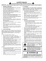
SAFETY RULES
Safe Operation Practices for Ride=On Mowers
iMPORTANT: THIS CUTTING MACHINE IS CAPABLE OF AMPUTATING HANDS AND FEET AND THROWING OBJECTS.
FAILURE TO OBSERVE THE FOLLOWING SAFETY iNSTRUCTIONS COULD RESULT IN SERIOUS INJURY OR DEATH.
I. GENERAL OPERATION
Read, understand, and follow all instructions in the manual
and on the machine before starting.
, Only allow responsible adults, who are familiar with the
instructions, to operate the machine.
, Clear the area of objecls such as rocks, toys, wire, etc.,
which could be picked up and thrown by the blade.
• Be sure the area is clear of other people before mowing. Stop
machine if anyone enters the area.
• Never carry passengers.
• Do not mow in reverse unless absolutely necessary. Always
look down and behind before and while backing.
• Be aware of the mower discharge direction and do not point
it at anyone. Do not operate the mower without either the
entire grass catcher or the guard in place.
• SFowdown before turning.
• Never leave a running machine unattended. Always turn off
blades, set parking brake, stop engine, and remove keys
before dismounting.
• Turn off blades when net mowing.
• Stop engine before removing grass catcher or unclogging
chute.
• Mow only in daylight or good artificial light.
Do not operate the machine while under the influence of
alcohol or drugs.
• Watch for traffic when operating near or crossing roadways.
• Use extra care when loading or unloading the machine into
a lrailer or truck.
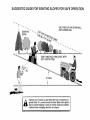
II. SLOPE OPERATION
Slopes are a major factor related to loss-of-control and
tipover accidents, which can result in severe injury or
death. All slopes require extra caution. If you cannot back
up the slope or if you feel uneasy on it, do not mow it.
DO:
• Mow up and down slopes, not across.
o Remove obstacles such as rocks, tree limbs, etc.
• Watch for holes, ruts, or bumps. Uneven terrain could
overturn the machine. Taft grass can hide obstacles.
• Use slow speed. Choose a low gear so that you will not have
to stop or shift while on the slope.
- Follow the manufacturer's recommendations for wheel
weights or counterweights to improve stability.
,, Use extra care with grass catchers or other attachments.
These can change the stabiJity of the machine.
• Keep all movement on the slopes slow and gradual. Do not
make sudden changes in speed or direction.
• Avoid starting or slopping on a slope. If tires lose traction,
disengage the blades and proceed slowly straight down the
slope.
DO NOT:
® Do not turn on slopes unless necessary, and then, turn slowly
and gradually downhill, if possible.
o Do not mow near drop-otis, ditches, or embankments, The
mower could suddenly turn over if a wheel is over the edge
of a cliff or ditch, or if an edge caves in.
. Do not mow on wet grass. Reduced traction could cause
sliding.
,, Do not try to stabilize the machine by putting your foot on the
ground.
Do not use grass catcher on steep slopes.
III. CHILDREN
Tragic accidents can occur if the operator is not alert to the
presence of children. Children are often attracted to the
machine and the mowing activity. Never assume that
children will remain where you last saw them.
o Keep children out of the mowing area and under the watchful
care of another responsible adult.
,, Be alert and turn machine off if children enter the area.
,, Before and when backing, look behind and down for small
children.
, Never carry children. They may fall off and be seriously
injured or interfere with safe machine operation.
,, Never allow children to operate the machine.
° Use extra care when approaching blind corners, shrubs,
trees, or other objects that may obscure vision.
IV.
o
°
it
e
ii
e
e
SERVICE
Use extra care in handling gasoline and other fuels. They are
flammable and vapors are explosive.
Use only an approved container.
Never remove gas cap or add fuel with the engine
running. Allow engine to cool before refueling. Do not
smoke,
Never refuel the machine indoors.
Never store the machine or fuel container inside where
there is an open flame, such as a water heater.
Never run a machine inside a dosed area.
Keep nuts and bolts, especially blade attachment bolts, tight
and keep equipment in good condition.
Never tamper with safety devices. Check their proper
operation regularly.
Keep machine free of grass, leaves, or other debris build-up.
Clean oil or fuel spillage. Allow machine to cool before
storing.
Stop and inspect the equipment if you strike an object.
Repair, if necessary, before restarting.
Never make adjustments or repairs with the engine running.
Grass catcher components are subject to wear, damage, and
deterioration, which could expose moving parts or allow
obiects to be thrown. Frequently check components and
replace with manufactureCs recommended parts, when nec-
essary.
Mower blades are sharp and can cut. Wrap the blade(s) or
wear gloves, and use extra caution when servicing them.
Check brake operation frequently. Adjust and service as
required.
Look for this symbol to point out important
safety precautions, it means
CAUTION!!! BECOME ALERT!!! YOUR
SAFETY IS INVOLVED.
CAUTION: Always disconnect spark plug
wire and place wire where it cannot contact
spark plug in order to prevent accidental
starting when" setting up; transporting,
adjusting or making repairs.
IH
WARNING
The engine exhaust from this product contains
chemicals known to the State of California to
cause cancer, birth defects, or other reproduc-
tive harm.

CONGRATULATIONS on your purchase of a Sears
Tractor. it has been designed, engineered and manufac-
tured to give you the best possible dependability and
performance.
Should you experience any problem you cannot easily
remedy, please contact your nearest Sears Authorized
Service Center/Department. We have competent, weft-
trained technicians and the proper tools to service or repair
this tractor.
Please read and retain this manual. The instructions will
enable you to assemble and maintain your tractor properly.
Always observe the "SAFETY RULES".
MODEL
NUMBER 917.259567
SERIAL
NUMBER
DATEOFPURCHASE
THE MODEL AND SERIAL NUMBERS WILL BE FOUND
ON A PLATE UNDER I-HE SEAT.
YOU SHOULD RECORD BOTH SERIAL NUMBER AND
DATE OF PURCHASE AND KEEP IN A SAFE PLACE
FOR FUTURE REFERENCE.
MAINTENANCE AGREEMENT
A Sears Maintenance Agreement is available on this prod-
uct. Contact your nearest Sears store for details.
CUSTOMER RESPONSIBILITIES
o _:_ead and observe the safety rules.
, "_oilowa regular schedule inmaintaining, caring for and
using your tractor.
- Follow the instructionsunder "Customer Responsibili-
ties" and "Storage" sections of this owner's manual.
WARNING: This tractor is equipped with an internal
combustion engine and should not be used on or near any
unimproved forest-covered, brush-covered or grass-cov-
ered land unless the engine's exhaust system is equipped
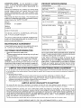
PRODUCT SPECIFICATIONS
HORSEPOWER: 19.5
GASOLINE CAPACITY 3.5 GALLONS
AND TYPE: UNLEADED REGULAR
OIL TYPE (API-SF/SG/SH): SAE 30 (above 32°F)
SAE 5W-30 (below 32°F)
OIL CAPACITY: 3.0 PINTS
SPARK PLUG: CHAMPION RJ19LM
(GAP: .030")
VALVE CLEARANCE: INTAKE: .004" - .006"
EXHAUST: .007" - .009"
GROUND SPEED (MPH): FORWARD:
1st 1.1
2nd 1.4
3rd 2_3
4th 3.5
5th 4.5
6th 5.7 -
REVERSE: 1.8
TIRE PRESSURE: FRONT: 14PSi
REAR: 10 PSi
CHARGING SYSTEM: 3 AMPS BATTERY
5 AMPS HEADLIGHTS
3ATTERY: AMP/HR: 30
MIN. CCA: 240
CASE SIZE: U1R
BLADEBOLT TORQUE: 30-35 FT.LBS.
with a spark arrester meeting applicable local or state laws
(if any). If a spark arrester is used, it should berfiaintained
in effective working order by the operator.
In the state of California the above is required by law
(Section 4442 of the Califorr_. Public Resources Code).
Other states may have simila_ws. Federal laws apply on
federal lands. A spark arrester for the muffler is available
through your nearest Sears Authorized Service Center!
Department (Soe REPAIR PARTS section ofthis manual).
LIMITED TWO YEAR WARRANTY ON CRAFTSMAN RIDING EQUIPMENT
Fortwo (2) years from the date of purchase,if this Craftsman RidingEquipment is maintained,lubricated and tuned up according
to the instructionsinthe owner's manual, Searswill repair or replace, free of charge, any parts foundto be defective in material or
workmanship.
This Warranty does not cover:
Expendableitems whichbecomeworn duringnormaluse,such as blades, spark plugs, air cleaners,belts,etc.
• Tire replacementor repaircaused by puncturesfrom outsideobjects, such as nails, thorns,stumps,or glass.
• Repairs necessary because of operatorabuse, negligence,improperstorageor accidentor the failureto maintain the
equipment according totheinstructionscontained inthe owner'smanual.
Ridingequipment usedfor commercial or rentalpurposes.
LIMITED 90 DAY WARRANTY ON BATTERY
For ninety (90) days from date of purchase, if any battery included with this riding equipment proves defective in material or
workmanship and our testing determinesthe batterywillnot hold a charge, Searswill replacethe battery at nocharge.
IN-HOME WARRANTY SERVICE ON YOUR CRAFTSMAN RIDING EQUIPMENT IS AVAILABLE AT NO-CHARGE FOR 30
DAYS FROM THE DATE OF PURCHASE. PLEASE CONTACT YOUR NEAREST SERVICE CENTER. AFTER 30 DAYS FROM
THE DATE OF PURCHASE, WARRANTY SERVICEIS AVAILABLEBY TAKING YOUR CRAFTSMAN RIDINGEQUIPMENTTO
YOUR NEARESTSEARS SERVICECENTER. (IN-HOMEWARRANTY SERVICEWILL STILL BE AVAILABLEAFTER 30 DAYS
FROM THE DATE OF PURCHASE BUT A STANDARD TRIP CHARGE WILL APPLY.) THIS WARRANTY APPLIES ONLY
WHILETHIS PRODUCT IS INTHE UNITEDSTATES.
This Warranty gives you specific legal rights,and you may also haveother rightswhich may vary from stateto state.
SEARS, ROEBUCK AND CO., D/817 WA, HOFFMAN ESTATES, IL 60179
3

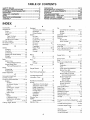
TABLE OF CONTENTS
SAFETY RULES ............................................................ 2
PRODUCT SPECIFICATIONS ...................................... 3
CUSTOMER RESPONSIBILITIES ..................... 3, 15-19
WARRANTY. ................................................................. 3
TABLE OF CONTENTS ................................................ 4
INDEX ............................................................................ 4
TRACTOR ACCESSORIES .......................................... 5
ASSEMBLY ................................................................ 7=9
OPERATION ........................................................... 10-14
MAINTENA_ICE SCHEDULE ...................................... 15
SERVICE AND ADJUSTMENTS ............................ 20-25
STORAGE ................................................................... 26
TROUBLESHOOTING ............................................ 27-28
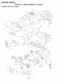
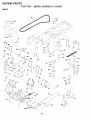
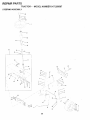
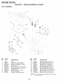
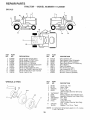
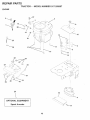
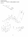
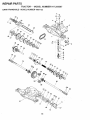
REPAIR PARTS - TRACTOR ................................. 30-47
REPAIR PARTS =ENGINE .................................... 48-53
PARTS ORDERING/SERVIICE .................. BACK PAGE
INDEX
A
Accessories ............................................ 5
Adjustments:
Brake ........................................... 22
Carburetor ................................... 25
Mower:
Front-To-Back ........................ 21
Side-To-Side .......................... 21
Throttle Control Cable ................. 24
Air Filter, Engine ................................. 18
Air Screen, Engine ............................. 18
Assembly ........................................... 7-g
B
Battery:
Charging .................................... 7-8
Cleaning ...................................... 17
Connecting ................................. 7-8
Starting with Weak Battery ......... 23
Storage ....................................... 26
Terminals .................................... 17
Belts:
Motion Drive
Removal/Replacement ........... 22
Mower Blade Drive
Removal/Replacement ........... 22
Blade:
Sharpening .................................. 16
Replacement ............................... 16
Brake Adjustment ............................... 22
C
Carburetor Adjustment ....................... 25
Controls, Tractor ................................ 11
Customer Responsibilities ............. 15-19
Engine:
Air Filter ................................... 18
Air Screen, Engine .................. 18
Battery ..................................... 17
Cooling Fins, Engine ............... 18
Engine Oil ............................... 17
Fuel Filter ................................ 19
Spark Plugs ............................. 19
Tractor:
Blades ..................................... 16
Lubrication Chart ..................... 15
Maintenance Schedule ........... 15
Tire Care ......................... 8,16,23
Cutting Height, Mower ....................... 12
E
Electrical:
Interlocks and Relays ................. 24
Schematic ................................... 29
Wiring Diagram ........................... 30
Engine:
Air Filter ....................................... 18
Air Screen ................................... 18
Cooling Fins, Engine ................... 18
Oil Change .................................. 17
Oi! Level ................................. 13,17
Oil Type ....................................... 17
Preparation ................................. t 3
Repair Parts ........................... 48-53
Starting ........................................ 14
Storage ....................................... 26
F
Filters:
Air ................................................ 18
Fuel ............................................. 19
Fuel:
Type ............................................ 13
Storage ....................................... 26
Fuse ................................................... 24
G
Gauge Wheels ..................................... 8
H
Hood Removal/Installation ................. 24
L
Leveling Mower Deck ......................... 21
Lubrication Chart ................................ 15
M
Maintenance Schedule ...................... 15
Mower:
Adjustment, Front-to-Back .......... 21
Adjustment, Side-to-Side ............ 21
Blade Sharpening ....................... 16
Blade Replacement ..................... 16
Cutting Height ............................. 12
installation ................................... 20
Operation .................................... 13
Removal ...................................... 20
Mowing Tips ....................... _............... 14
Muffler ................................................ 19
Spark Arrester .......................... 3,40
Mulcher Plate ....................................... 9
O
Oil:
Cold Weather Conditions ....... 13,17
Engine ......................................... 17
Storage ....................................... 26
Operation ...................................... 11-14
Operating Mower ................................ 13
Options:
Accessories ................................... 5
Spark Arrester .......................... 3,40
P
Parking Brake ................................ 11-12
Parts Bag ............................................. 6
Parts, ReplacemenlJRepair ........... 30-47
Product Specifications ........................... 3
R
Repair Parts .................................. 30-47
S
Safety Rules ..... ,.......... ,............ .............. 2
Seat ...................................................... 8
Service and Adjustments .............. 20-25
Brake ........................................... 22
Carburetor ................................... 25
Fuse ............................................ 24
Hood Removal/Installation .......... 24
Motion Drive Belt
Removal/Replacement ........... 22
Mower Blade Drive Belt
RemovallReplacement ........... 22
Mower Adjustment:
Front-to-Back ......................... 21
Side-to-Side ........................... 21
Mower installation ....................... 20
Mower Removal .......................... 20
Tire Care ............................. 8,16,23
Slope Guide Sheet ............................. 55
Spark Plugs ........................................ 19
Specifications ....................................... 3
Starting the Engine ....................... 13-14
Steering Wheel ................................ 7,23
Stopping the Tractor ........................... 12
Storage..:..........:,..:....: ........................ 26
T
Throttle Control Cable Adjustment ..... 24
Tires ........................................... 8,t6,23
Trouble Shooting Chart .................. 27-28
Transaxle Repair Parts ................. 46-47
W
Warranty ............................................... 3
Wiring Diagram .................................. 30
Wiring Schematic ............................... 29

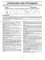
AND ATTAq ENTS
These accessories and attachments were available through most Sears retail outlets and service centers when thetractor was purchased.
Most Sears stores can order these items for you when you provide the model number of your tractor.
ENGINE MAINTENANCE
SPARK PLUG GAS CAN ENGINEOIL FUELSTABiLiZER AIR FILTER BLADES BELTS
PERFORMANCE
Sears offers a wide variety of attachments that fit your tractor. Many of these are listed below with brief explanations of how they can help
you. This list was current at the time of publication; however, it may change in future years - more attachments may be added, changes
may be made in these attachments, or some may no longer be available or fit your model. Contact your nearest Sears store for the
accessories and attachments that are available for your tractor.
Most of these attachments do not require additional hitches or conversion kits (those that do are indicated) and are designed for easy
attaching and detaching.
AERATOR promotes deep root growth for a healthy lawn. Ta-
pered 2.5-inch steel spikes mounted on 10-inch diameter discs
puncture holes in soil at close intervals to let moisture soak in.
Steel weight tray for increased penetration.
BAGGER lets you collect grass clippings and leaves for a
healthier, neater looking lawn. Two Permanex containers hold
30-gallen plastic bags.
BUMPER protects front end of tractor from damage.
CARTS make hauling easy. Variety of sizes available, plus
accessories such as side panel kits, tool caddy, cart cover,
protective mat and dolly.
CORING AERATOR takes small plugs out of soil to allow mois-
ture and nutrients to reach grass roots. 36-inch swath. 24
hardened steel coring tips. 150 lb. capacity weight tray.
EASY OIL DRAIN VALVE makes oil changes easier, faster.
FRONT NOSE ROLLER canters in front of mower deck to reduce
chances of "scalping" on uneven terrain.
GANG HITCH lets you tow 2or 3pull-behind attachments atonce,
such as sweepers, dethatchers, aerators (not for use with rollers,
carts or other heavy attachments).
GAUGE WHEELS on both sides of the mower deck reduce
chances of "scalping" on uneven terrain. For mower decks not so
equipped,
MULCH RAKE/DETHATCHER loosens soil and flips thatch and
matted leaves to lawn surface for easy pickup. Twenty spring line
teeth. Usefultepreparebareareasforseeding. Availabteforfront
or rear mounting. HiGH PERFORMANCE REEL-ACTION
SPRING TINE DETHATCHER covers 36-inch wide path and
tosses thatch into large hopper. Mounts behind tractor.
MULCHING CLOSE-OUT PLATE KIT, once installed, lets you
mulch, discharge or bag clippings (bagger optional) without
changing blades. For models not equipped as 3-in-1 Convertible
mowers. See "MOWER" in the Repair Parts section of this
manual.
RAMP TOPS AND FEET let you load and unload tractor from a
pickup truck. Use with 2 x 8 or 2 x 10 lumber.
ROLLER for smoother lawn surface. 36-inch wide, 18-inch
diameter water-tight drum holds up to 390 Ibs. of weight. Rounded
edges prevent harm to turf. Adjustable scraper automatically
cleans drum.
SNOW BLADEforsnow removalonly. 14-inch high,48-inch wide
blade clears 42-inch path when angled left or right. Raises, lowers
with side lever, Adjustable skids; replaceable, reversible scraper
bar. (Use with tire chains and wheel weights and/or rear drawbar
weight.)
SNOWTHROWER has 40-inch swath. Drum-type auger handles
powdery and wet!heavy snow. Mounts easily with simple pin
arrangement. Discharge chute adjusts from tractor seat. 6-inch
diameter spout discharges snow 10 to 50 feet. Lift controlled at
tractor seat. (Use with chains and wheel weights and/or rear
drawbar weight.)
SPRAYERS use 12-volt DC electric motor that connects to the
tractor battery or ether 12-volt source. Includes booms for
automatic spraying and hand held wand for spot spraying. Wand
has adjustable spray pattern. For applying herbicides, insecti-
cides, fungicides and liquid fertilizers.
SPREADER/SEEDERS make seeding, fertilizing, and weed kill-
ing easy. Broadcast spreaders are also useful for granular de-
icers and sand.
SWEEPERS let you collect grass clippings and leaves.
TILLER has 5 hp engine and 36-inch swath to prepare seed beds,
cultivate and compost garden residue. Tiller has its own built-in
fift and depth control system and does NOT require a sleeve hitch.
Fits any lawn, yard or garden tractor. Simply hook up tothe tractor
drawbar and go! Optional accessories convert unit for
dethatching, aerating, hilling...without toois.
TIRE CHAINS are heavy duty; closely spaced extra-large cross
links give smooth ride, outstanding traction.
TRACTOR CAB has heavy duty vinyl fabric over tubular steel
frame, ABS plastic top; clear plastic windshield offers 360 degree
visibility. Hinged metal doors with catch. Keeps operator warm
and dry. Remove vinyl sides and windshields for use as sun
protector in summer. Optional accessories include: tinted/
tempered solid safety glass windshield with hand operated wiper;
12-volt amber caution light for mounting on cab top.
VACS for powerful collection of heavy grass clippings and leaves.
Optional wand attachment to pick up debris in hard-to-reach
p_ces. VACICHIPPER includesa chipper-shredder.
WEIGHT BRACKET for drawba_ for snow removal applications.
Uses (1) 55 lb. weight.
WHEEL WEIGHTS for rear wheels provide needed traction for
snow removal or dozing heavy materials.

CONTENTS OF RDWARE PACK
Parts Bag contents shown full size
\
\
\
/
(1) Hex Bolt
3/8-16 x 1
(1) Large Flat Washer
(1) Hex Bolt 5/16-18 x 1-1/4 (1) Locknut 5/16-18
(1) Lockwasher 3/8
_r
_4 Bolt 5/16-18
1) Washer
17/32 x
1-3/16.x 12
Gauge
(1) Hex Bolt
1/2-13 x 1
C
(1) Lock Washer 1/2
(2) Screws __
Washers #10 x 5/8
(2) Lock
#1o
(2) Washers
3/16 x 3/4 (2) Weld
x 16 Gauge Nuts #10
(2) Hex Bofts 1/4-20 x 3/4
(2) Hex Nuts 1/4-20
(2) Washers 9/32 x 5/8 x 16 Gauge
_ 2 kockWashers 1/4
6
Parts packed separately in carton
Seat
Video
Cassette
Steering
Wheel
Manual
Steering
Boot
Mulcher
Plate
Parts Bag
,q
t
i
t
I
Parts bag contents not shown full size
(2) Washers 3/8
x 7/8 x 14 Gauge
©
(2) Center-
...... lock Nuts
Steering Wheel,
Adapter
(2) Gauge
Wheels
.y ..... -. (2) Keys
,\
\
/ Steering
ch Hook \_ _____ _ Wheel
Assemblys '- ........................_ Insert
Steering
Extension
Shaft
Slope Sheet

ASSEMBLY
Your new tractor has been assembled at the factoq! with exception of those parts left unassembled for shipping purposes.
To ensure safe and proper operation of your tractor all parts and hardware you assemble must be tightened securely. Use
the correct tools as necessary to insure proper tightness.
TOOLS REQUIRED FOR ASSEMBLY
A socket wrench set will make assembly easier. Standard
wrench sizes are listed.
(1) 3/4" Socket w/drive rachet
(2) 7/16" wrenches Phillips Screwdriver
(2) 1/2" wrenches Tire pressure gauge
(1) 9/16" wrench Utility knife
When right or left hand is mentioned in this manual, it
means when you are in the operating position (seated
behind the steering wheel).
TO REMOVE TRACTOR FROM CARTON
UNPACK CARTON
Remove all accessible loose parts and parts cartons
from carton (See page 6).
, Cut, from top to bottom, along lines on all four corners
of carton, and lay panels flat.
Check for any additional loose parts or cartons and
remove.
BEFORE ROLLING TRACTOR OFF SKID
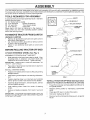
ATTACH STEERING WHEEL (See Fig. 1)
ASSEMBLE EXTENSION SHAFT AND BOOT
® Slide extension shaft onto lower steering shaft. Align
mounting holes in extension and lower shafts and
instal} 5116 hex bolt and Iocknut. Tighten securely.
IMPORTANT: TIGHTEN BOLT AND NUT SECURELY TO
18-22 FT. LBS TORQUE.
Place tabs of steering boot over tab slots in dash and
push down to secure.
INSTALL STEERING WHEEL
o Position front wheels of the tractor so they are pointing
straight forward.
o Slide steering wheel adapter onto steering shaft exten-
sion.
, Position steering wheel so cross bars are horizontal
(left to right) and slide inside boot and onto adapter.
o Assemble large flat washer, 3/8 lock washer, 3/8 hex
bo}t and tighten securely.
- Snap steering wheel insert into center of steering
wheel.
• Remove protective materials from tractor hood and
grill.
iMPORTANT: CHECK FOR AND REMOVE ANY STAPLES
IN SKIDTHAT MAY PUNCTLIRETIRESWHERETRACTOR
IS TO ROLL OFF SKID.
_-_._ _.._--.,-_INSERT
__ 318 HEX BOLT
LARGE FLAT
WASHER
STEERIN
WHEEL
/
\ /
STEERING
BOOT
FIG. 1
TO ROLL TRACTOR OFF SKID (See Operation
section for location and function of controls)
Press lift lever plunger and raise attachment lift lever to
its highest position.
- Release parking brake by depressing clutch!brake
pedal.
- Place gearshift lever in neutral (N) position.
. Roll tractor backwards off skid.
, Remove banding holding discharge guard up against
tractor.

ASSE LY
HOW TO SET UP YOUR TRACTOR
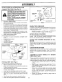
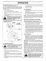
CONNECT BATTERY (See Fig. 2)
CAUTION: Do not short battery termi=
rials by allowing a wrench or any other
object to contact both terminals at the
same time. Before connecting battery,
remove metal bracelets, wristwatch
bands, rings, etc.
Positive terminal must be connected
first to prevent sparking from acciden-
tal grounding.
Lift hood to raised position.
• Open terminal access doors, remove terminal protec-
tive caps and discard.
• If this battery is put into service after month and year
indicated on label (label located between terminals)
charge battery for minimum of one hour at 6-10 amps.
, First connect RED battery cable to positive (+) battery
terminal with hex bolt, flat washer, lock washer and hex
nut as shown. Tighten securely.
• Connect BLACK grounding cable to negative (-) bat-
tery terminal with remaining hex bolt, flat washer, lock
washer and hex nut. Tighten securely.
• Close terminal access doors.
Use terminal access doors for:
• inspection for secure connections (to tighten hard-
ware).
• Inspection for corrosion.
• Testing battery.
, Jumping (if required).
, Periodic charging.
LOCK FLAT
DISCARD TERMINAL WASHER WASHER
PROTECTIVE CAPS HEX NUT
• .... _ _ ii
TERMINAL
ACCESS
DOOR
POSiTiVE
(RED)
CABLE
HEX
BOLT
NEGATIVE
(BLACK)
CABLE
INSTALL SEAT (See Fig. 3)
Adjust seat before tightening adjustment bolt.
• Remove cardboard packing on seat pan.
• Place seat on seat pan and assemble shoulder bolt.
Tighten shoulder bolt securely.
Assemble adjustment bolt, lock washer and fiat washer
loosely. Do not tighten.
, Lower seat into operating position and sit on seat.
- Slide seat until a comfortable position is reached which
allows you to press clutch/brake pedal all the way
down.
• Get off seat without moving its adjusted position.
o Raise seat and tighten adjustment bolt securely.
SEAT
SEAT PAN
SHOULDER
BOLT \
3E FLAT WASHER
ADJUSTMENT
BOLT LOCK WASHER
FiG. 3
CHECK TiRE PRESSURE
The tires on your tractor were overinflated at the factory for
shipping purposes. Correct tire pressure is important for
best cutting performance.
Reduce tire pressure to PSI shown in "PRODUCT
SPECIFICATIONS" on page 3 of this manual.
CHECK DECK LEVELNESS
For best cutting results, mower housing should be properly
leveled. See "TO LEVEL MOWER HOUSING" in the
Service and Adjustments section of this manual.
CHECK FOR PROPER POSITION OF ALL
BELTS
See the figures that are shown for replacing motion and
mower blade drive belts in the Service and Adjustments
section of this manual. Verify that the belts are routed
correctly.
CHECK BRAKE SYSTEM
After you learn how to operate your tractor, check to see
that the brake is properly adjusted. See "TO ADJUST
BRAKE" in the Service and Adjustments section of this
manual.
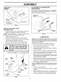
ASSEMBLE GAUGE WHEELS TO MOWER
DECK (See Fig. 4)
The gauge wheels are designed to keep the mower deck in
proper position when operating mower. Be sure they are
properly adjusted to ensure optimum mower performance.
* Assemble gauge wheels with tractor on a flat Ievel
surface.
, Adjust mower to desired cutting height (See 'q'O AD-
JUST MOWER CUTTING HEIGHT" in the Operation
•section of this manual). " ....
- With mower in desired height of cut position, gauge-
wheels *hould be assembled so they are slightly off the
ground. Install gauge wheel in appropriate hole with
shoulder bolt, 3/8 washer, and 3/8-16 Iocknut and
tighten securely.
, Repeat for opposite side installing gauge wheel in
same adjustment hole.

BLY
GAUGE WHEEL
MOUNTING
BRACKET _ _
\\
318-16 \
LOCKNUT \
318" WASHER
GAUGE WHEEL"
SHOULDERBOLT
FiG. 4
iNSTALL MULCHER PLATE
(See Figs. 5 & 6)
Install two latch hooks to mulcher plate using screw,
washer, lock washer, and weld nut as shown.
NOTE: Pre-assemble weld nut to latch hook by inserting
weld nut from the top with hook pointing down.
Tighten hardware securely.
Raise and hold deflector shield in upright position.
• Place front of mulcher plate over front of mower deck
opening and slide into place, as shown.
• Hook front latch into hole on front of mower deck.
Hook rear latch into hole on back of mower deck.
CAUTION: Do not remove discharge
guard from mower. Raise and hold
guard when attaching mulcher plate
and allow it to rest on plate while in
operation.
WELD NUT FROM THE TOP
LOCK
WELD WASHER
NUT. SCREW
LATCH
HOOK POINTS DOWN
\
HOOK
WASHER
MULCHER
PLATE
LOCK
WASHER
FIG. 5
WELD
NUT
TO CONVERT TO BAGGING OR
DISCHARGING
Simply remove mulcher plate and store in a safe place.
Your mower is now ready for discharging or installation of
optional grass catcher accessory.
\
LATCH
HOOKS
FIG. 6
,/CHECKLIST
BEFORE YOU OPERATE AND ENJOY YOUR NEW
TRACTOR, WE WISH TOASSURE THAT YOU RECEIVE
THE BESTPERFORMANCEAND SATISFACTtON FROM
THIS QUALITY PRODUCT.
PLEASE REVIEW THE FOLLOWING CHECKLIST:
,/ Al! assembly instructions have been completed.
,/ No remaining loose parts in carton.
,/ Battery is properly prepared and charged. (Minimum
1 hour at 6 amps).
,z Seat is adjusted comfortably and tightened securely.
,/ All tires are properly inflated. (For shipping purposes,
the tires were overinflated at the factory).
,/ Be sure mower deck is properly leveled side-to-side/
front-to-rear for best cutting results. (Tires must be
properly inflated for leveling).
,z Check mower and drive belts. Be sure they are routed
properly around pulleys and inside all belt keepers.
,/ Check wiring. See that all connections are still secure
and wires are properly clamped.
WHILE LEARNING HOW TO USE YOUR TRACTOR, PAY
EXTRA ATTENTION TO THE FOLLOWING IMPORTANT
ITEMS:
,/. Engine oil is at properlevel. -
¢" Fuel tank is filled with fresh, clean, regular unleaded
gasoline.
,/ Become familiar with all controls - their location and
function. Operate them before you start the engine.
,/ Be sure brake system is in safe operating condition.

OPERATION
These symbols may appear on your tractor or in literature supplied with the product. Learn and understand their meaning.
BATTERY
ENGINE ON
4!,
,t
CAUTION OR REVERSE FORWARD
WARNING
ENGINE OFF OIL PRESSURE CLUTCH
CHOKE MOWER HEIGHTFUEL
N
REVERSE NEUTRAL
ATTACHMENT
CLUTCH ENGAGED
MOWER LIFT
FAST SLOW
Qi
LIGHTS ON OVER TEMP
LIGHT
G
PARKING BRAKE UNLOCKED
LOCKED
PARKING BRAKE
@
DIFFERENTIAL
LOCK
H
HIGH LOW
ATTACHMENT
CLUTCH DISENGAGED
IGNITION
DANGER, KEEP HANDS AND FEETAWAY
HYDROSTATIC FREE WHEEL
(Hydro Models only)
10

OPERATIC
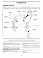
KNOW YOUR TRACTOR
READ THIS OWNER'S MANUAL AND SAFETY RULES BEFORE OPERATING YOUR TRACTOR
Compare the illustrations with yourtractortofamiliarizeyourselfwiththelocations ofvariouscontrolsand adjustments. Save
this manual for future reference.
ATTACHMENT iGNITION LIGHT SWITCH
CLUTCH LEVER SWITCH POSITION
" t _ " - " LiFT LEVER
," ," PLUNGER
ATTACHMENT
LiFT LEVER
CLUTCH/BRAKE
PEDAL
HEIGHT
ADJUSTMENT
KNOB
PARKING BRAKE
GEARSHIFT''"
LEVER
FIG. 7
Our tractors conform to the safety standards of the American National Standards Institute.
ATTACHMENT CLUTCH LEVER: Used to engage the
mower blades, or other attachments mounted to your
tractor.
LIGHT SWITCH: Turns the headlights on and off.
THROTTLE CONTROL: Used to control engine speed.
CHOKE CONTROL: Used when starting a cold engine.
CLUTCH/BRAKE PEDAL: Used for declutching and brak-
ing the tractor and starting the engine,
PARKING BRAKE: Locks clutch/brake pedal into the
brake position.
GEARSHIFT LEVER: Selects the speed and direction of
tractor.
ATTACHMENT LIFT LEVER: Used to raise and lower the
mower deck or other attachments mounted to your tractor.
LIFT LEVER PLUNGER: Used to release attachment lift
lever when changing its position,
IGNITION SWITCH: Used for starting and stopping the
engine.
HEIGHT ADJ USTM ENT KNO B: Used toadjust the mower
cutting height.
AMMETER: Indicates battery charging (+) or discharging
(-).
11

OPERATION
i........ can
_ _="_ J resuitinsevereeyedamage. Alwayswearsafetyglassesoreyeshieidswhileoperatingyour
_ tractor or performing any adjustments or repairs. We recommend a wide vision safety mask
_ s e athe p et cles or standard safety glasses. _ _
HOW TO USE YOUR TRACTOR
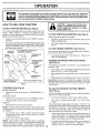
TO SET PARKING BRAKE (See Fig. 8)
Your tractor isequipped with an operator presence sensing
switch. When engine is running, any attempt by the
operator to leave the seat without first setting the parking
brake will shut off the engine.
• Depress clutch/brake pedal into full "BRAKE" position
and hold.
Place parking brake lever in "ENGAGED" position and
release pressu refrom clutch/brake pedal. Pedal should
remain in "BRAKE" position. Make sure parking brake
will hold tractor secure.
THROTTLE
CONTROL
CHOKE
CONTROL
ATTACHMENT CLUTCH LEVER
"ENGAGED"POSITION
"DISENGAGED"
POSITION
"BRAKE"
POSITION
PARKING BRAKE
POSITION
GEARSHIFT
LEVER
CLUTCH/BRAKE PEDAL
"DRIVE" POSITION
"DISENGAGED"
POSITION
HEIGHT ADJUSTMENT KNOB
FIG. 8
CAU'FION: Always stop tractor com-
pletely, as described above, before leavo
ing the operator's position; to empty
grass catcher, etc.
TO USE THROTTLE CONTROL (See Fig. 8)
Always operate engine at full throttle.
Operating engine at less than full throttle reduces the
battery charging rate.
Full throttle offers the best bagging and mower perfor-
mance.
TO USE CHOKE CONTROL (See Fig= 8)
Use choke control whenever you are starting a cold engine.
Do not use to start a warm engine.
To engage choke control, pull knob out. Slowly push
knob in to disengage.
TO MOVE FORWARD AND BACKWARD
(See Fig. 8)
The direction and speed of movement is controtlecl by the
gearshift lever.
= Start tractor with clutch/brake pedal depressed and
gearshift lever in neutral (N) position.
• Move gearshift and range shift levers to desired posi-
tion.
• Slowly release clutch/brake pedal to start movement.
IMPORTANT: BRING TRACTOR TO A COMPLETE STOP
BEFORE SHIFTING OR CHANGING GEARS. FAILURE
TO DO SO WlLL SHORTEN THE USEFUL LIFE OF YOUR
TRANSAXLE.
STOPPING (See Fig. 8)
MOWER BLADES -
= Move attachment clutch lever to "DISENGAGED" po-
sition.
GROUND DRIVE-
• Depress clutch/brake pedal into full "BRAKE" position.
• Move gearshift lever to neutral (N) position.
ENGINE -
• Move throttle control to slow position.
NOTE: Failure to move throttle control to slow position and
allowing engine to idle before stopping may cause engine
to "backfire".
, Turn ignition key to "OFF" position and remove key.
Always remove key when leaving tractor to prevent
unauthorized use.
• Never use choke to stop engine.
NOTE: Under certain conditions when tractor is standing
idle with the engine running, hot engine exhaust gases may
cause "browning" of grass. To eliminate this possibility,
always stop engine when stopping tractor on grass areas.
12
TO ADJUST MOWER CUTTING HEIGHT
(See Fig. 8)
The cutting height iscontrolled byturning the height adjust-
ment knob in desired direction.
Turn knob clockwise (f-_l) to raise cutting height.
Turn knob counterclockwise (_-'_)to lower cutting
height.
The cutting height range isapproximately 1-1/2" to 4". The
heights are measured from the ground to the blade tip with
the engine not running. These. heigbts are approximate
and may vary depending upon soil conditions, height of
grass and types of grass being mowed.
, The average lawn should be cut to approximately 2-1/2
inches during the cool season and to over 3 inches
during hot months. For healthier and better looking
lawns, mow often and after moderate growth.
For best cutting performance, grass over 6 inches in
height should be mowed twice. Make the first cut
relatively high; the second to desired height.

OPERATION
TO OPERATE MOWER (See Fig. 9)
Your tractor isequipped with an operator presence sensing
switch. Any attempt by the operator to leave the seat with
the engine running and the attachment clutch engaged will
shut off the engine.
Select desired height of cut.
Lower mower with attachment lift control.
Start mower blades by engaging attachment clutch
control.
TO STOP MOWER BLADES - disengage attachment
clutch control.
CAUTION: Do not operate the mower
without either the entire grass catcher,
on mowers so equipped, or the dis=
charge guard in place.
ATTACHMENT CLUTCH LEVER
"DISENGAGED" POSiTiON
"ENGAGED"
POSITION
ATTACHMENT
LIFT LEVER
POSITION
POSiTiON
\
DISCHARGE
GUARD
FIG. 9
TO OPERATE ON HILLS
i---A----CAUT-/ON: Do not drive up o_
j_ hitls with slopes greater than 15° and
_onot drive across any slope.
• Choose the slowest speed before starting up or down
hills.
', Avoid stopping or changing speed on hills.
If slowing is necessary, move throttle control lever to
slower position.
If stopping is absolutely necessary, push clutch/brake
pedal quickly to brake position and engage parking
brake.
Move gearshift lever to 1st gear. Be sure you have
allowed room for tractor to rol! slightly as you restart
movement.
,, To restart movement, slowly release parking brake and
clutch/brake pedal.
* Make all turns slowly.
TO TRANSPORT
° Raise attachment lift to highest position with attach-
ment lift control.
• When pushing or towing your tractor, be sure gearshift
!ever is in neutral (N) position.
• Do not push or tow tractor at more than five (5) MPH.
NOTE: To protect hood from damage when transporting
your tractor on atruckor at railer, be sure hood isclosed and
secured to tractor. Use an appropriate means of tying hood
to tractor (rope, cord, etc.).
BEFORE STARTING THE ENGINE
CHECK ENGINE OIL LEVEL (See Fig. 15)
, The engine in your tractor has been shipped, from the
factory, already filled with summer weight oil.
Check engine oil with tractor on level ground.
• Remove oil fill cap/dipstick and wipe clean, reinsert the
dipstick and screw cap tight, wait for a few seconds,
remove and read oil level. If necessary, add oil until
"FULL" mark on dipstick is reached. Do not overfill.
• For cold weather operation you should change oil for
easier starting (See "OIL VISCOSITY CHART' in the
Customer Responsibilities section of this manual).
• To change engine oil, see the Customer Responsibili-
ties section in this manual.
!3
ADD GASOLINE
o Fill fuel tank. Use fresh, clean, regular unleaded
gasoline with a minimum of 87 octane. (Use of leaded
gasoline will increase carbon and lead oxide deposits
and reduce valve life). Do not mix oil with gasoline.
Purchase fuel in quantities that can be used within 30
days to assure fuel freshness.
IMPORTANT: WHEN OPERATING IN TEMPERATURES
BELOW 32°F(0°C), USE FRESH, CLEAN WINTER GRADE
GASOLINE TO HELP INSURE GOOD COLD WEATHER
STARTING.
WARNING: Experience indicates that alcohol blended
fuels (ca!led gasohol or using ethanol or methanol) can
attract moistu re which leads to separation and formation of
acids during storage. Acidic gas can damage the fuel
system of an engine while in storage. To avoid engine
problems, the fuel system should be emptied before stor-
age of 30 days or longer. Drain the gas tank, start the
engine and let it run until the fuel lines and carburetor are
empty. Use fresh fuel next'season. See Storage Instruc-
tions for additional informatLon. Never use engine or
carburetor cleaner products in the fuel tank or permanent
damage may occur.
CAUTION: Fill to bottom of gas tank
filler neck. Do not overfill. Wipe off any
spilled oil or fuel. Do not store, spill or
use gasoline near an open flame.

TO START ENGINE (See Fig. 8)
When starting the engine for the first time or if the engine
has run out of fuel, it will take extra cranking time to move
fuel from the tank to the engine.
o Sit on seat in operating position, depress clutch/brake
pedal and set parking brake.
= Place gear shift lever in neutral (N) position.
• Move attachment clutch to "DISENGAGED" position.
• Move throttle control to fast position
• Pull choke control out for a cold engine start attempt.
For a warm engine start attempt the choke control may
not be needed.
Note: Before starting, read the warm and cold starting
procedures below.
Insert key into ignition and turn keyc!ockwise to"START"
position and release key as soon as engine starts. Do
not run starter continuously for more than fifteen sec-
onds per minute. If the engine does not start after
several attempts, push choke control in, wait a few
minutes and try again. Ifengine still does not start, pull
the choke control out and retry.
WARM WEATHER STARTING (50° F and above)
= When engine starts, slowly push choke control in until
the engine begins to run smoothly. Ifthe engine starts
to run roughly, pull the choke control out slightly for a
few seconds and then continue to push the control in
slowly.
The attachments and ground drive can now be used. If
the engine does not accept the load, restart the engine
and allow itto warm up for one minute using the choke
as described above.
COLD WEATHER STARTING (50° F and below)
• When engine starts, slowly push choke control in until
the engine begins to run smoothly. Continue to push
the choke control in small steps allowing the engine to
accept small changes in speed and load, until the
choke control is fully in. If the engine starts to run
roughly, pull the choke control out slightly for a few
seconds and then continue to push the control in
slowly. This may require an engine warm-up period
from several seconds to several minutes, depending
on the temperature.
, The attachments can be used du ring the engine warm-
up period and may require the choke control be pulled
out slightly,
NOTE: If at a high altitude (above 3000 feet) or in cold
temperatures (below 32 F) the carburetor fuel mixture may
need to be adjusted for best engine performance. See "TO
ADJUST CARBURETOR" in the Service and Adjustments
section of this manual.
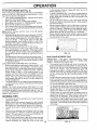
MOWING TIPS
• Tire chains can not be used when the mower housing is
attached to tractor.
o Mower should be properly leveled for best mowing
performance. See "TO LEVEL MOWER HOUSING" in
the Service and Adjustments section of this manual.
° The left hand side of mower should be used for trim-
ming.
Drive so that clippings are discharged onto the area
that has been cut. Have the cut area to the right of the
tractor. This will result in a more even distribution of
clippings and more uniform cutting.
• When mowing large areas, start by turning to the right
so that clippings will discharge away from shrubs,
fences, driveways, etc. After one or two rounds, mow
in the opposite direction making left hand turns until
finished (See Fig. 10 ).
, tf grass is extremely tall, it should be mowed twice to
reduce load and possible fire hazard from dried clip-
pings. Make first cut relatively high; the second to the
desired height.
• Do not mow grass when it is wet. Wet grass will plug
mower and leave undesirable clumps. Allow grass to
dry before mowing.
• Always operate engine at full throttle when mowing to
assure better mowing performance and proper dis-
charge of material. Regulate ground speed by select-
ing a low enough gear to give the mower cutting
performance as well as the quality of cut desired.
• When operating attachments, select a ground speed
that will suit the terrain and give best performance of
the attachment being used.
FIG. 10
MULCHING MOWING TIPS
IMPORTANT: FOR BEST PERFORMANCE, KEEP
MOWER HOUSING FREE OF BUILT-UP GRASS AND
TRASH. CLEAN AFTER EACH USE.
• The special mulching blade will recut the grass clip-
pings many times and reduce them in size so that as
they fall onto the lawn they will disperse into the grass
and not be noticed. Also, the mulched grass will
biodegrade quickly to provide nutrients for the lawn.
Always mulch with your highest engine (blade) speed
as this will provide the best recutting action of the
blades.
, Avoid cutting your lawn when it is wet. Wet grass tends
to form clumps and interferes with the mulching action.
The best time to mow your lawn is the early afternoon.
At this time the grass has dried and the newly cut area
will not be exposed to the direct sun.
o For best results, adjust the mower cutting height so that
the mower cuts off only the top one-third of the grass
blades (See Fig. 11). For extremely heavy mulching,
reduce your width of cut and mow slowly.
• Certain types of grass and grass conditions may re-
quire that an area be mulched a second time to com-
pletely hide the clippings. When doing a second cut,
mow across or perpendicular to the first cut path.
• Change your cutting pattern from week to week. Mow
north to south one week then change to east to west the
next week. This will help prevent matting and graining
of the lawn.
MAX 1/3
!fib !
Ill
14 FIG. 11

CUSTOMER ;IBILITIES
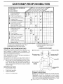
MAINTENANCE SCHEDULE
FILL iN DATES
AS YOU COMPLETE
REGULAR SERVICE
Check Brake Operation
Check Tire Pressure
T
Check for Loose Fasteners
AR Sharpen!Replace Mower Blades
C Lubrication Chart
T Check Battery Level/Recharge
0 Clean Battery and Terminals
a Check Transaxle Cooling
Adjust Blade Belt(s) Tension
Adjust Motion Drive Belt(s) Tension
Check Engine Oil Level
Change Engine Oil
CIean Air Filter
E
N clean Air Screen
G inspect Muffler/Spark Arrester
I Replace Oil Filter (It equipped)
_ CleanEngine Cooling Fins--
Replace Spark Plug
Replace Air Filter Paper Cartridge
Replace Fuel Filter !
v'
v'
i/
!/
i
i/
i/
i/
i/
i/
i/ i/
, Iv'l
1 -Change more often when operating under a heavy load or in high ambient temperatures.
2 - Service more often when operating in dirty or dusty conditions.
3 - If equipped with oil filter, change oil every 50 hours.
4 - Replace blades more often when mowing in sandy soil.
_ERVICE DATES
5 - If equipped with adjustable system.
6 - Not required if equipped with maintenance-lree battery.
7 - Tighten front axle pivot bolt to 35 ft,qbs, maximum.
Do not overtighten.
GENERAL RECOMMENDATIONS
The warranty on this tractor does not cover items that have
been subjected to operator abuse or negligence. To
receive full value from the warranty, operator must maintain
tractor as instructed in this manual.
Some adjustments will need to be made periodically to
properly maintain your tractor.
All adjustments in the Service and Adjustments section of
this manual should be checked at least once each season.
LUBRICATION CHART
(_) "FRONT WHEEL (_)
BEARING ZERK BEARING ZERK
Once a year you should replace the spark plug, dean
or replace air filter, and check blades and belts for
wear. A new spark plug and clean air filter assure
proper air-fuel mixture and help your engine run better
and last longer.
©
CLUTCH
PIVOT(S)
ENGINE (_
BEFORE EACH USE
o Check engine oil level.
* Check brake operation.
- Check tire pressure.
- Check for loose fasteners.
®
PIVOTS
(_) SAE 30 OR 10W30 MOTOR OIL
(_) GENERAL PURPOSE GREASE
G) REFER TO CUSTOMER RESPONSIBILtT_ES
"ENGINE" SECTION
IMPORTANT: DO NOT OIL OR GREASE THE PIVOT POINTS
WHICH HAVE SPECIAL NYLON BEARINGS. VISCOUS LUBRI-
CANTS WiLL ATTRACT DUST AND DiRT THAT WILL SHORTEN
THE LIFE OF THE SELF-LUBRICATING BEARINGS. IF YOU
FEEL THEY MUST BE LUBRICATED, USE ONLY A DRY, POW-
15 DERED GRAPHITE TYPE LUBRICANT SPARINGLY.

CUSTOMER RESPONSIBILITIES
TRACTOR
Always observe safety rules when performing any mainte-
nance.
BRAKE OPERATION
If tractor requires more than six (6) feet stopping distance
at high speed in highest gear, then brake must be adjusted.
(See "TO ADJUST BRAKE" in the Service and Adjust-
ments section of this manual).
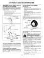
TIRES
" Maintain proper air pressure in all tires (See "PROD-
UCT SPECIFICATIONS" on page 3 of this manual).
,, Keep tires free of gasoline, oil, or insect control chemi-
cals which can harm rubber.
• Avoid stumps, stones, deep ruts, sharp objects and
other hazards that may cause tire damage.
NOTE: To seal tire punctures and prevent flat tires due to
slow leaks, tire sealant may be purchased from your local
parts dealer. Tire sealant also prevents tire dry rot and
corrosion.
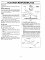
BLADE CARE
For best results mower blades must be kept sharp. Re-
place bent or damaged blades.
BLADE REMOVAL (See Fig. 12)
= Raise mower to highest position to allow access to
blades.
° Remove hex bolt, lock washer and flat washer securing
blade.
° Install new or resharpened blade with trailing edge up
towards deck as shown.
• Reassemble hex bolt, lock washer and fiat washer in
exact order as shown.
• Tighten bolt securely (30-35 Ft. Lbs. torque).
IMPORTANT: BLADE BOLTISGRADE8HEATTREATED.
NOTE: We do not recommend sharpening blade-but ifyou
do, be sure the blade is balanced.
BLADE
FLAT WASHER
_ MANDREL
ASSEMBLY
TRAlUNGEDGE
HEXBOLT
(GRADE8)*-_. "@
*A GRADE 8 HEAT TREATED BOLT CAN BE
iDENTIFIED BY SIX LINES ON THE BOLT HEAD.
FIG. 12
TO SHARPEN BLADE (See Fig. 13)
Care should be taken to keep the blade balanced. An
unbalanced blade will cause excessive vibration and even-
tual damage to mower and engine.
• The blade can be sharpened with a file or on a grinding
wheel. Do not attempt to sharpen while on the mower.
• To check blade balance, you will need a 5/8" diameter
steel bolt, pin, or a cone balancer. (When using a cone
ba[ancer, follow the instructions supplied with bal-
ancer).
Slide blade on to an unthreaded portion of the steel bolt
or pin and hold the bolt or pin parallel with the ground.
If blade is balanced, it should remain in a horizontal
position, if either end of the blade moves downward,
sharpen the heavy end until the blade is balanced.
NOTE: Do not use a nail for balancing blade. The lobes of
the center hole may appear to be centered, but are not.
/ /
CENTER HOLE j
/
5/8" BOLT
OR PIN
BLADE
FIG. 13
16

C STOMER RESPON
BATTERY
Your tractor has a battery charging system which is suffi-
cient for normal use. However, periodic charging of the
battery with an automotive charger will extend its life.
Keep battery and terminals clean.
Keep battery bolts tight.
Keep small vent holes open.
• Recharge at 6-10 amperes for 1 hour.
TO CLEAN BATTERY AND TERMINALS
Corrosion and dirt on the battery and terminals can cause
the battery to "leak" power.
Remove terminal guard.
, Disconnect BLACK battery cable first then RED bat-
tery cable and remove battery from tractor.
• Rinse the battery with plain water and dry.
• Clean terminals and battery cable ends with wire brush
until bright.
. Coal terminals with grease or petroleum jelly.
• Reinstall battery (See "CONNECT BATTERY" in the
Assembly section of this manual).
V=BELTS
Check V-belts for deterioration and wear after 100 hours of
operation and replace if necessary. The belts are not
adjustable. Replace belts if they begin to slip from wear.
TRANSAXLE COOLING
Keep transaxle free from build-up of dirt and chaff which
can restrict cooling.
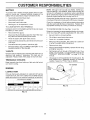
ENGINE
LUBRICATION
Only use high quality detergent oil rated with API service
classification SF, SG or SH, Select the oil's SAE viscosity
grade according to your expected operating temperature.
SAE VISCOSITY GRADES
I
[
r I
°F "20 ' 0 ° 30 '/ 32° 40 ° 60" B0 / 100 °
i°C -30 _ "20 ° -10 _ 0' 10° 20 ' 30" 40 °
[- - TEMPERATUt::{E RANGE ANTICIPATE6 BEFORE NEXT OIL CHANGE
FIG. 14
BILITIES
NOTE: Although multi-viscosity oils (5W30, 10W30 etc.)
improve starting in cold weather, these multi-viscosity oils
will result in increased oil consumption when used above
32°F. Check your engine oil level more frequently to avoid
possible engine damage from running low on oil.
Change the oil after every 25 hours of operation or at least
once ayear ifthe tractor is not used for 25 hours in one year.
Check the crankcase oil level before starting the engine
and after each eight (8) hours of operation. Tighten oil fill
cap/dipstick securely each time you check the oil level.
TO CHANGE ENGINE OIL (See Figs. 14 and 15)
Determine temperature range expected before oil change.
All oil must meet API service classification SF, SG or SH.
• Be sure tractor is on level surface.
° Oil will drain more freely when warm,
• Catch oil in a suitable container.
Remove oil fill cap/dipstick. Be careful not to allow dirt
to enter the engine when changing oil.
Remove drain plug.
• After oil has drained completely, replace oil drain plug
and tighten securely.
Refill engine with oil through oil fill dipstick tube. Pour
slowly. Do not overfill. For approximate capacity see
"PRODUCT SPECIFICATIONS" on page 3 of this
manual.
• Use gauge on oil fill cap/dipstick for checking level. Be
sure dipstick cap is tightened securely .for. accurate
reading. Keep oil at "FULL" line on dipstick.
OIL
DRAIN
PLUG
AIR SCREEN
OIL FILL
CAPiDIPSTSICK
FIG. 15
17

C
E
ILITIES
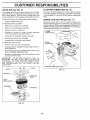
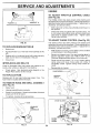
AIR FILTER (See Fig. 16)
Your engine will not run properly using a dirty air filter.
Clean the foam pre-cleaner after every 25 hours of opera-
tion or every season. Service paper cartridge every 100
hours of operation or every season, whichever occurs first.
Service air cleaner more often under dusty conditions.
• Remove knob(s) and cover.
TO SERVICE PRE-CLEANER
• Slide foam pre-cleaner off cartridge.
• Wash it in liquid detergent and water.
• Squeeze it dry in a clean cloth.
Saturate it in engine oil. Wrap it in clean, absorbent
cloth and squeeze to remove excess oil.
• If very dirty or damaged, replace pre-cleaner.
. Reinstall pre-cleaner over cartridge.
, Reinstall cover and secure with knob(s).
TO SERVICE CARTRIDGE
Remove wing nuts and cartridge plate.
• Carefully remove cartridge to prevent debris from en-
tering carburetor.
, Clean cartridge by tapping gently on flat surface. Ifvery
dirty or damaged, replace cartridge.
, Reinstall cartridge plate, wing nuts, precleaner, cover
and secure with knob(s).
IMPORTANT: PETROLEUM SOLVENTS, SUCH AS
KEROSENE, ARE NOT TO BE USED TO CLEAN THE
CARTRIDGE. THEY MAY CAUSE DETERIORATION OF
THE CARTRIDGE. DO NOT OIL CARTRIDGE. DO NOT
CLEAN AIR SCREEN (See Fig. 16)
Air screen must be kept free of dirt and chaff to prevent
engine damage from overheating. Clean with a wire brush
or compressed air to remove dirt and stubborn dried gum
fibers.
ENGINE COOLING FINS (See Fig. 17)
Remove any dust, dirt or oil from engine cooling fins to
prevent engine damage from overheating. Air guide covers
must be removed. Remove side panels and hood (See "TO
REMOVE HOOD AND GRILL ASSEMBLY" in the Service
and Adjustments section of this manual).
TOP AIR
GUIDE COVER,
ENGINE
COOLING FINS
USE PRESSURIZED AIR TO CLEAN OR DRY
CARTRIDGE.
FOAM
PRE-CLEANER -_.
AIR SCREEN
CARTRIDGE
\
AIR GUIDECOVER (BOTH SIDES)
FIG. 17
FIG. 16
18

C ER RESPO ;IBILITIE
MUFFLER
inspect and replace corroded muffler and spark arrester (if
equipped) as it could create a fire hazard and/or damage.
SPARK PLUGS
Replace spark plugs at the beginning of each mowing
season or after every 100 hours of operation, whichever
occurs first. Spark plug type and gap setting are shown in
"PRODUCT SPECIFICATIONS" on page 3 of this manual.
CLAMP, CLAMP
FUEL
IN-LINE FUEL FILTER (See Fig. 18)
The fuel filter should be replaced once each season. If fuel
filter becomes clogged, obstructing fuel flow to carburetor,
replacement is required.
- With engine cool, remove filter and plug fuel line
sections.
= Place new fuel filter in position in fuel line with arrow
pointing towards carburetor.
- Be sure there are no fuel line leaks and clamps are
properly positioned.
, Immediately wipe up any spilled gasoline.
FIG. 18
CLEANING
Clean engine, battery, seat, finish, etc. of all foreign
matter.
Keep finished surfaces and wheels free of all gasoline,
oil, etc.
• Protect painted surfaces with automotive type wax.
We do not recommend using a garden hose to clean your
tractor unless the electrical system, muffler, air filter and
carburetor are covered to keep water out. Water in engine
can result in a shortened engine life.
19

SERVICE AND ADJUSTMENTS
CAUTION: BEFORE PERFORMING ANY SERVICE OR ADJUSTMENTS:
Depress ciutcWbrake pedal fully and set parking brake.
Place gearshift lever in neutral (N) position.
• Place attachment clutch in "DISENGAGED" position.
, Turn ignition key "OFF" and remove key.
= Make sure the blades and all moving parts have completely stopped.
- Disconnect spark plug wire from spark plug and place wire where itcannot come in contact with
plug.
TRACTOR
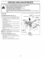
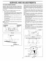
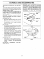
TO REMOVE MOWER (See Fig. 19)
Mower will be easier to remove from the right side of tractor.
• Place attachment clutch in "DISENGAGED" position.
• Move attachment lift lever forward to lower mower to its
lowest position.
• Roll belt off engine pulley.
, Disconnect clutch rod from clutch lever by removing
retainer spring.
® Disconnect anti-sway bar from chassis bracket by
removing retainer spring.
° Disconnect suspension arms from rear deck brackets
by removing retainer springs.
= Disconnect front links from deck by removing retainer
springs,
Raise lift lever to raise suspension arms. Slide mower
out from under tractor.
IMPORTANT: IF AN ATTACHMENT OTHER THAN THE
MOWER IS TO BE MOUNTED TO THE TRACTOR,
REMOVE THE FRONT LINKS.
TO iNSTALL MOWER (See Fig. 19)
® Raise attachment lift lever to its highest position.
• Slide mower under tractor with discharge guard to right
side of tractor.
- Lower lift lever to its lowest position.
• Install mower in reverse order of removal instructions.
LEVER
RETAINER
SPRING
SUSPENSION
PULLEY
RETAINER
SPRINGS
BOTH SIDES
RETAINER
SPRING
ANTI-SWAY BAR
RETAINER
SPRINGS
(BOTH SIDES)
FIG. 19
2O
Page is loading ...
Page is loading ...
Page is loading ...
Page is loading ...
Page is loading ...
Page is loading ...
Page is loading ...
Page is loading ...
Page is loading ...
Page is loading ...
Page is loading ...
Page is loading ...
Page is loading ...
Page is loading ...
Page is loading ...
Page is loading ...
Page is loading ...
Page is loading ...
Page is loading ...
Page is loading ...
Page is loading ...
Page is loading ...
Page is loading ...
Page is loading ...
Page is loading ...
Page is loading ...
Page is loading ...
Page is loading ...
Page is loading ...
Page is loading ...
Page is loading ...
Page is loading ...
Page is loading ...
Page is loading ...
Page is loading ...
Page is loading ...
-
 1
1
-
 2
2
-
 3
3
-
 4
4
-
 5
5
-
 6
6
-
 7
7
-
 8
8
-
 9
9
-
 10
10
-
 11
11
-
 12
12
-
 13
13
-
 14
14
-
 15
15
-
 16
16
-
 17
17
-
 18
18
-
 19
19
-
 20
20
-
 21
21
-
 22
22
-
 23
23
-
 24
24
-
 25
25
-
 26
26
-
 27
27
-
 28
28
-
 29
29
-
 30
30
-
 31
31
-
 32
32
-
 33
33
-
 34
34
-
 35
35
-
 36
36
-
 37
37
-
 38
38
-
 39
39
-
 40
40
-
 41
41
-
 42
42
-
 43
43
-
 44
44
-
 45
45
-
 46
46
-
 47
47
-
 48
48
-
 49
49
-
 50
50
-
 51
51
-
 52
52
-
 53
53
-
 54
54
-
 55
55
-
 56
56


Ask a question and I''ll find the answer in the document
Finding information in a document is now easier with AI
Related papers
Other documents
-
Craftsman 917288130 Owner's manual
-
-
-
-
-
-
-
-
-