Agilent Technologies Option H48 Multiport Test Set Z5623A User manual
- Category
- Networking
- Type
- User manual
This manual is also suitable for

Agilent Technologies
Z5623A Option H48
Multiport Test Set
User’s and Service Guide
Manufacturing Part Number: Z5623-90016
Printed in USA
June 2005
© Copyright 2000-2002, 2005 Agilent Technologies, Inc. All rights reserved.

ii
Warranty Statement
THE MATERIAL CONTAINED IN THIS DOCUMENT IS PROVIDED “AS IS,” AND IS
SUBJECT TO BEING CHANGED, WITHOUT NOTICE, IN FUTURE EDITIONS. FURTHER,
TO THE MAXIMUM EXTENT PERMITTED BY APPLICABLE LAW, AGILENT DISCLAIMS
ALL WARRANTIES, EITHER EXPRESS OR IMPLIED WITH REGARD TO THIS MANUAL
AND ANY INFORMATION CONTAINED HEREIN, INCLUDING BUT NOT LIMITED TO THE
IMPLIED WARRANTIES OF MERCHANTABILITY AND FITNESS FOR A PARTICULAR
PURPOSE. AGILENT SHALL NOT BE LIABLE FOR ERRORS OR FOR INCIDENTAL
OR CONSEQUENTIAL DAMAGES IN CONNECTION WITH THE FURNISHING, USE, OR
PERFORMANCE OF THIS DOCUMENT OR ANY INFORMATION CONTAINED HEREIN.
SHOULD AGILENT AND THE USER HAVE A SEPARATE WRITTEN AGREEMENT WITH
WARRANTY TERMS COVERING THE MATERIAL IN THIS DOCUMENT THAT CONFLICT
WITH THESE TERMS, THE WARRANTY TERMS IN THE SEPARATE AGREEMENT WILL
CONTROL.
DFARS/Restricted Rights Notice
If software is for use in the performance of a U.S. Government prime contract or
subcontract, Software is delivered and licensed as “Commercial computer software” as
defined in DFAR 252.227-7014 (June 1995), or as a “commercial item” as defined in
FAR 2.101(a) or as “Restricted computer software” as defined in FAR 52.227-19 (June
1987) or any equivalent agency regulation or contract clause. Use, duplication or
disclosure of Software is subject to Agilent Technologies’ standard commercial license
terms, and non-DOD Departments and Agencies of the U.S. Government will receive no
greater than Restricted Rights as defined in FAR 52.227-19(c)(1-2) (June 1987). U.S.
Government users will receive no greater than Limited Rights as defined in FAR
52.227-14 (June 1987) or DFAR 252.227-7015 (b)(2) (November 1995), as applicable in
any technical data.

iii
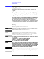
Safety Notes
The following safety notes are used throughout this document. Familiarize yourself
with each of these notes and its meaning before performing any of the procedures in
this document.
WARNING Warning denotes a hazard. It calls attention to a procedure
which, if not correctly performed or adhered to, could result in
injury or loss of life. Do not proceed beyond a warning note
until the indicated conditions are fully understood and met.
CAUTION Caution denotes a hazard. It calls attention to a procedure that, if not
correctly performed or adhered to, could result in damage to or
destruction of the instrument. Do not proceed beyond a caution sign
until the indicated conditions are fully understood and met.
Statement of Compliance
This instrument has been designed and tested in accordance with IEC Publication 1010, Safety
Requirements for Electronic Measuring Apparatus, and has been supplied in a safe condition. The
instruction documentation contains information and warnings which must be followed by the user to
ensure safe operation and to maintain the instrument in a safe condition.
Definitions
• Specifications describe the performance of parameters covered by the product warranty
(temperature –0 to 55 °C, unless otherwise noted.)
• Typical describes additional product performance information that is not covered by the
product warranty. It is performance beyond specification that 80% of the units exhibit
with a 95% confidence level over the temperature range 20 to 30 °C. Typical
performance does not include measurement uncertainty.
• Nominal values indicate expected performance or describe product performance that is
useful in the application of the product, but is not covered by the product warranty.

iv

Contents
Contents-1
1. Instrument Description
Overview . . . . . . . . . . . . . . . . . . . . . . . . . . . . . . . . . . . . . . . . . . . . . . . . . . . . . . 1-2
Specifications . . . . . . . . . . . . . . . . . . . . . . . . . . . . . . . . . . . . . . . . . . . . . . . . . . . 1-3
Guaranteed Performance. . . . . . . . . . . . . . . . . . . . . . . . . . . . . . . . . . . . . . . . . 1-4
Typical Performance. . . . . . . . . . . . . . . . . . . . . . . . . . . . . . . . . . . . . . . . . . . . 1-5
Electrical Requirements . . . . . . . . . . . . . . . . . . . . . . . . . . . . . . . . . . . . . . . . . . . 1-6
Environmental Requirements. . . . . . . . . . . . . . . . . . . . . . . . . . . . . . . . . . . . . . . 1-6
Operating Environment. . . . . . . . . . . . . . . . . . . . . . . . . . . . . . . . . . . . . . . . . . 1-6
Non-Operating Storage Conditions . . . . . . . . . . . . . . . . . . . . . . . . . . . . . . . . 1-6
General Characteristics. . . . . . . . . . . . . . . . . . . . . . . . . . . . . . . . . . . . . . . . . . . . 1-7
Weight. . . . . . . . . . . . . . . . . . . . . . . . . . . . . . . . . . . . . . . . . . . . . . . . . . . . . . . 1-7
Cabinet Dimensions . . . . . . . . . . . . . . . . . . . . . . . . . . . . . . . . . . . . . . . . . . . . 1-7
Miscellaneous Characteristics. . . . . . . . . . . . . . . . . . . . . . . . . . . . . . . . . . . . . 1-7
Available Options. . . . . . . . . . . . . . . . . . . . . . . . . . . . . . . . . . . . . . . . . . . . . . . . 1-7
UK6. . . . . . . . . . . . . . . . . . . . . . . . . . . . . . . . . . . . . . . . . . . . . . . . . . . . . . . . . 1-7
Rack Ear Mounts . . . . . . . . . . . . . . . . . . . . . . . . . . . . . . . . . . . . . . . . . . . . . . 1-7
Cleaning and Shipping Instructions . . . . . . . . . . . . . . . . . . . . . . . . . . . . . . . . . . 1-8
2. Installation
Checking the Shipment. . . . . . . . . . . . . . . . . . . . . . . . . . . . . . . . . . . . . . . . . . . . 2-2
Recommended Additional Equipment . . . . . . . . . . . . . . . . . . . . . . . . . . . . . . . . 2-3
Familiarization with Safety Requirements . . . . . . . . . . . . . . . . . . . . . . . . . . . . . 2-4
Electrical Preparations . . . . . . . . . . . . . . . . . . . . . . . . . . . . . . . . . . . . . . . . . . . . 2-4
Environmental Preparations . . . . . . . . . . . . . . . . . . . . . . . . . . . . . . . . . . . . . . . . 2-7
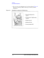
Test Set Familiarization . . . . . . . . . . . . . . . . . . . . . . . . . . . . . . . . . . . . . . . . . . . 2-9
Front Panel . . . . . . . . . . . . . . . . . . . . . . . . . . . . . . . . . . . . . . . . . . . . . . . . . . . 2-9
Rear Panel. . . . . . . . . . . . . . . . . . . . . . . . . . . . . . . . . . . . . . . . . . . . . . . . . . . 2-11
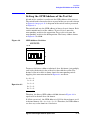
Setting the GPIB Address of the Test Set . . . . . . . . . . . . . . . . . . . . . . . . . . . . 2-13
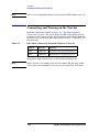
Connecting and Turning on the Test Set . . . . . . . . . . . . . . . . . . . . . . . . . . . . . 2-14
3. Using the Network Analyzer to Control the Test Set
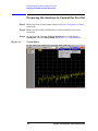
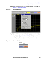
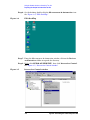
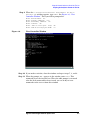
Preparing the Analyzer to Control the Test Set . . . . . . . . . . . . . . . . . . . . . . . . . 3-2
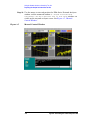
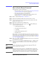
How to Send a Manual Command . . . . . . . . . . . . . . . . . . . . . . . . . . . . . . . . . . . 3-7
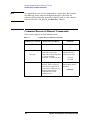
Common Errors in Manual Commands . . . . . . . . . . . . . . . . . . . . . . . . . . . . . . . 3-8
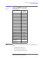
A List of GPIB Commands . . . . . . . . . . . . . . . . . . . . . . . . . . . . . . . . . . . . . . . . 3-9
Restoring the Analyzer to its Normal Configuration . . . . . . . . . . . . . . . . . . . . 3-12
Disaster Recovery. . . . . . . . . . . . . . . . . . . . . . . . . . . . . . . . . . . . . . . . . . . . . . . 3-13

Contents-2
Malfunctioning Command Window . . . . . . . . . . . . . . . . . . . . . . . . . . . . . . . 3-13
Malfunctioning Network Analyzer. . . . . . . . . . . . . . . . . . . . . . . . . . . . . . . . 3-18
4. Calibrating the Network Analyzer
Performing the Calibration . . . . . . . . . . . . . . . . . . . . . . . . . . . . . . . . . . . . . . . . . 4-2
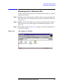
Renaming the Calibration File . . . . . . . . . . . . . . . . . . . . . . . . . . . . . . . . . . . . . . 4-7
Recalling and Examining Calibrations. . . . . . . . . . . . . . . . . . . . . . . . . . . . . . . 4-14
How to Recall a Calibration . . . . . . . . . . . . . . . . . . . . . . . . . . . . . . . . . . . . . 4-14
Method 1. Calibration File Is Not On “Quick Recall” List. . . . . . . . . . . . 4-14
Method 2. Calibration File Is On “Quick Recall” List . . . . . . . . . . . . . . . 4-16
How to Turn a Calibration On and Off. . . . . . . . . . . . . . . . . . . . . . . . . . . . . 4-16
How to Examine the Properties of a Calibration . . . . . . . . . . . . . . . . . . . . . 4-18
5. Performance Verification
Setting Test Limits . . . . . . . . . . . . . . . . . . . . . . . . . . . . . . . . . . . . . . . . . . . . . . . 5-2
Test Strategy. . . . . . . . . . . . . . . . . . . . . . . . . . . . . . . . . . . . . . . . . . . . . . . . . . . . 5-4
Insertion Loss . . . . . . . . . . . . . . . . . . . . . . . . . . . . . . . . . . . . . . . . . . . . . . . . . 5-5
Return Loss. . . . . . . . . . . . . . . . . . . . . . . . . . . . . . . . . . . . . . . . . . . . . . . . . . . 5-5
Crosstalk . . . . . . . . . . . . . . . . . . . . . . . . . . . . . . . . . . . . . . . . . . . . . . . . . . . . . 5-6
Setting Up Limit Testing . . . . . . . . . . . . . . . . . . . . . . . . . . . . . . . . . . . . . . . . . . 5-7
Limit Testing for Insertion Loss . . . . . . . . . . . . . . . . . . . . . . . . . . . . . . . . . . . 5-8
Recalling the Calibration. . . . . . . . . . . . . . . . . . . . . . . . . . . . . . . . . . . . . . . 5-8
Specifying Measurement Type, Title, and Scaling . . . . . . . . . . . . . . . . . . . 5-8
Setting Up the Limit Table . . . . . . . . . . . . . . . . . . . . . . . . . . . . . . . . . . . . 5-12
Turning On Limit Lines and Limit Testing. . . . . . . . . . . . . . . . . . . . . . . . 5-14
Saving the Limit Test File. . . . . . . . . . . . . . . . . . . . . . . . . . . . . . . . . . . . . 5-15
Checking the Limit Test File. . . . . . . . . . . . . . . . . . . . . . . . . . . . . . . . . . . 5-17
Limit Testing for Return Loss (Port Active) . . . . . . . . . . . . . . . . . . . . . . . . 5-19
Recalling the Calibration. . . . . . . . . . . . . . . . . . . . . . . . . . . . . . . . . . . . . . 5-19
Specifying Measurement Type, Title, and Scaling . . . . . . . . . . . . . . . . . . 5-19
Setting Up the Limit Table . . . . . . . . . . . . . . . . . . . . . . . . . . . . . . . . . . . . 5-20
Turning On Limit Lines and Limit Testing. . . . . . . . . . . . . . . . . . . . . . . . 5-21
Saving the Limit Test File. . . . . . . . . . . . . . . . . . . . . . . . . . . . . . . . . . . . . 5-22
Checking the Limit Test File. . . . . . . . . . . . . . . . . . . . . . . . . . . . . . . . . . . 5-22
Limit Testing for Return Loss (Port Off) . . . . . . . . . . . . . . . . . . . . . . . . . . . 5-24
Recalling the “Port Active” Limit Test File . . . . . . . . . . . . . . . . . . . . . . . 5-24
Specifying the Title. . . . . . . . . . . . . . . . . . . . . . . . . . . . . . . . . . . . . . . . . . 5-24
Setting Up the Limit Table . . . . . . . . . . . . . . . . . . . . . . . . . . . . . . . . . . . . 5-24
Saving the Limit Test File. . . . . . . . . . . . . . . . . . . . . . . . . . . . . . . . . . . . . 5-25
Recalling the Limit Test File. . . . . . . . . . . . . . . . . . . . . . . . . . . . . . . . . . . 5-25

Contents
Contents-3
Limit Testing for Crosstalk . . . . . . . . . . . . . . . . . . . . . . . . . . . . . . . . . . . . . 5-26
Specifying Output Power . . . . . . . . . . . . . . . . . . . . . . . . . . . . . . . . . . . . . 5-26
Specifying IF Bandwidth and Averaging . . . . . . . . . . . . . . . . . . . . . . . . . 5-28
Specifying Measurement Type, Title, and Scaling . . . . . . . . . . . . . . . . . . 5-32
Setting Up the Limit Table . . . . . . . . . . . . . . . . . . . . . . . . . . . . . . . . . . . . 5-34
Turning On Limit Lines and Limit Testing. . . . . . . . . . . . . . . . . . . . . . . . 5-35
Saving the Limit Test File. . . . . . . . . . . . . . . . . . . . . . . . . . . . . . . . . . . . . 5-35
Recalling the Limit Test File. . . . . . . . . . . . . . . . . . . . . . . . . . . . . . . . . . . 5-35
Verifying Return Loss and Insertion Loss Specifications . . . . . . . . . . . . . . . . 5-36
Measurements Using The Reflection Port . . . . . . . . . . . . . . . . . . . . . . . . . . 5-36
Measurements Using The Transmission Port . . . . . . . . . . . . . . . . . . . . . . . . 5-37
Verifying Crosstalk Specs . . . . . . . . . . . . . . . . . . . . . . . . . . . . . . . . . . . . . . . . 5-39
6. Measuring Multiport Devices
Calibrating the Test System . . . . . . . . . . . . . . . . . . . . . . . . . . . . . . . . . . . . . . . . 6-2
7. Advanced Topics
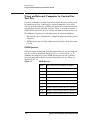
Using an External Computer to Control the Test Set. . . . . . . . . . . . . . . . . . . . . 7-2
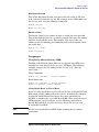
GPIB Queries . . . . . . . . . . . . . . . . . . . . . . . . . . . . . . . . . . . . . . . . . . . . . . . . . 7-2
Box Identification . . . . . . . . . . . . . . . . . . . . . . . . . . . . . . . . . . . . . . . . . . . . 7-3
Switch Count . . . . . . . . . . . . . . . . . . . . . . . . . . . . . . . . . . . . . . . . . . . . . . . 7-3
Languages . . . . . . . . . . . . . . . . . . . . . . . . . . . . . . . . . . . . . . . . . . . . . . . . . . . . 7-3
Using Rocky Mountain Basic (RMB). . . . . . . . . . . . . . . . . . . . . . . . . . . . . 7-3
Using Quick Basic or Visual Basic. . . . . . . . . . . . . . . . . . . . . . . . . . . . . . . 7-3
Using HPVEE . . . . . . . . . . . . . . . . . . . . . . . . . . . . . . . . . . . . . . . . . . . . . . . 7-4
Using National Instruments VISA . . . . . . . . . . . . . . . . . . . . . . . . . . . . . . . 7-5
Using the Control Lines Connector . . . . . . . . . . . . . . . . . . . . . . . . . . . . . . . . . . 7-6
Control Line Commands for 9-Pin Connector:. . . . . . . . . . . . . . . . . . . . . . . . 7-6
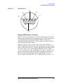
Suggested External Circuitry . . . . . . . . . . . . . . . . . . . . . . . . . . . . . . . . . . . . . 7-7
8. Service
Adjustments . . . . . . . . . . . . . . . . . . . . . . . . . . . . . . . . . . . . . . . . . . . . . . . . . . . . 8-2
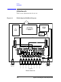
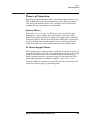
Theory of Operation . . . . . . . . . . . . . . . . . . . . . . . . . . . . . . . . . . . . . . . . . . . . . . 8-3
System Theory . . . . . . . . . . . . . . . . . . . . . . . . . . . . . . . . . . . . . . . . . . . . . . . . 8-3
A1 Power Supply Theory . . . . . . . . . . . . . . . . . . . . . . . . . . . . . . . . . . . . . . . . 8-3
A2 Controller and A3 Switch Driver Board Theory. . . . . . . . . . . . . . . . . . . . 8-4
A4 Front Panel Display Theory . . . . . . . . . . . . . . . . . . . . . . . . . . . . . . . . . . . 8-4

Contents-4
Connector Replacement . . . . . . . . . . . . . . . . . . . . . . . . . . . . . . . . . . . . . . . . . 8-4
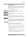
Troubleshooting . . . . . . . . . . . . . . . . . . . . . . . . . . . . . . . . . . . . . . . . . . . . . . . . . 8-5
General Troubleshooting Notes . . . . . . . . . . . . . . . . . . . . . . . . . . . . . . . . . . . 8-5
Troubleshooting Power Supply Problems . . . . . . . . . . . . . . . . . . . . . . . . . . . 8-5
Troubleshooting the Front Panel Board . . . . . . . . . . . . . . . . . . . . . . . . . . . . . 8-6
Troubleshooting the Controller and Switch Driver Boards . . . . . . . . . . . . . . 8-6
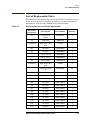
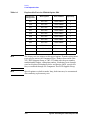
List of Replaceable Parts . . . . . . . . . . . . . . . . . . . . . . . . . . . . . . . . . . . . . . . . . . 8-7
9. Safety and Regulatory Information
Safety Information . . . . . . . . . . . . . . . . . . . . . . . . . . . . . . . . . . . . . . . . . . . . . . . 9-2
Warnings. . . . . . . . . . . . . . . . . . . . . . . . . . . . . . . . . . . . . . . . . . . . . . . . . . . . . 9-2
Cautions . . . . . . . . . . . . . . . . . . . . . . . . . . . . . . . . . . . . . . . . . . . . . . . . . . . . . 9-3
Instrument Markings. . . . . . . . . . . . . . . . . . . . . . . . . . . . . . . . . . . . . . . . . . . . 9-4
Regulatory Information . . . . . . . . . . . . . . . . . . . . . . . . . . . . . . . . . . . . . . . . . . . 9-5
Statement of Compliance with IEC 1010 . . . . . . . . . . . . . . . . . . . . . . . . . . . . 9-5
Declaration of Compliance with German Noise Requirements . . . . . . . . . . . 9-5
10. Contacting Agilent
Contacting Agilent . . . . . . . . . . . . . . . . . . . . . . . . . . . . . . . . . . . . . . . . . . . . . . 10-2

Agilent Technologies Z5623A Option H48 1-1
1 Instrument Description
This chapter contains the following sections:
• Overview
• Specifications
• Electrical Requirements
• Environmental Requirements
• General Characteristics
• Available Options
• Cleaning and Shipping Instructions

1-2 Agilent Technologies Z5623A Option H48
Instrument Description
Overview
Overview
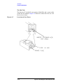
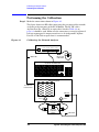
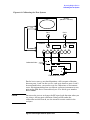
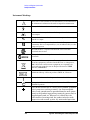
The Agilent Z5623A Option H48 Multiport Test Set is designed for use
with 50 Ω Network Analyzers such as the Agilent PNA Series (Models
E8356A, E8357A, and E8358A). Figure 1-1 shows a typical equipment
setup.
The test set reduces the time required to test multiport devices having
up to eight ports (distribution amplifiers, taps, switches, couplers, etc.).
It does this by reducing the number of device reconnects the operator
must perform. The test set can connect each of its test ports to any of
the following:
• Reflection Port
• Transmission Port
• 50 Ω termination internal to the test set.
Switching is performed with mechanical switches.
The test set is controlled by means of its GPIB interface. The control
can be performed either by a PNA Series network analyzer or by an
external computer.
NOTE
This User's and Service Guide documents the use of the test set with an
Agilent E8358A network analyzer.
Figure 1-1 Typical Equipment Setup
Network Analyzer
Port 1
Port 2
Reflection
Port
Transmission
Port
Z5623A Option H48
1
2
3
4
56
7
8
Test Ports
RF Cables

Agilent Technologies Z5623A Option H48 1-3
Instrument Description
Specifications
Specifications
Agilent provides two different types of specifications for the test set:
• Guaranteed performance specs
• Typical performance specs
Typical performance specs have been benchmarked during product
development, but are not tested by the factory and are not guaranteed.

1-4 Agilent Technologies Z5623A Option H48
Instrument Description
Specifications
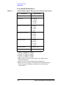
Guaranteed Performance
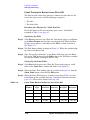
Table 1-1 Agilent Z5623A Option H48 Guaranteed Performance Specs
Parameter Specification
Frequency Range 300 kHz to 9.0 GHz
Crosstalk
a
1) –110 dB
b
2) –105 dB
c
3) –95 dB
d
4) –90 dB
e
Return Loss (port active)
f
1) 24 dB
b
2) 18 dB
c
3) 14 dB
d
4) 9 dB
e
Return Loss (port off)
g
1) 26 dB
b
2) 20 dB
c
3) 16 dB
d
4) 14 dB
e
Insertion Loss
h
1) 1.5 dB
b
2) 2.0 dB
c
3) 2.5 dB
d
4) 3.5 dB
e
Switch Lifetime 5 million cycles
Maximum Input Power
1 Watt (RF + DC)
i
a.Between any two non-connected signal paths
b. Band 1 (300 kHz to 1.3 GHz)
c. Band 2 (1.3 GHz to 3.0 GHz)
d. Band 3 (3.0 GHz to 6.0 GHz)
e. Band 4 (6.0 GHz to 9.0 GHz)
f.When using an external termination on the Reflection or
Transmission port
g.When using one of the 50 Ω internal terminations
h.From any test set port to the Reflection or Transmission port
i. Set by the power handling capability of the 50 Ω internal
terminations

Agilent Technologies Z5623A Option H48 1-5
Instrument Description
Specifications
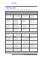
Typical Performance
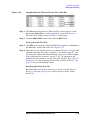
Table 1-2 Agilent Z5623A Option H48 Typical Performance Specs
Parameter Typical Performance
Source Power (max)
a
1) –8.0 dBm
b
2) –8.0 dBm
c
3) –7.0 dBm
d
4) –1.0 dBm
e
Dynamic Range (max)
f
1) 110 dB
b
2) 105 dB
c
3) 95 dB
d
4) 90 dB
e
Cycle Time (minimum;
IF BW = 35 kHz)
g
1) 430 mS (Dynamic Range = 86 dB)
b
2) 430 mS (Dynamic Range = 89 dB)
c
3) 430 mS (Dynamic Range = 78 dB)
d
4) 430 mS (Dynamic Range = 71 dB)
e
Cycle Time (@ 100 dB
Dynamic Range; IF
BW = 3 kHz)
g
2) 900 mS
c
3) 900 mS
d
Switching Time 11 mS
a. Power measured at test ports 1-8 on Z5623A Option
H48 when connected to the E8358A using the
8120-4782 RF Jumper cables supplied.
b. Band 1 (300 kHz to 1.3 GHz)
c. Band 2 (1.3 GHz to 3.0 GHz)
d. Band 3 (3.0 GHz to 6.0 GHz)
e. Band 4 (6.0 GHz to 9.0 GHz)
f. IF Bandwidth set to 10 Hz
g. Conditions: 2 Windows, 4 Channels, 8 Traces,
2-port cal, no band crossings, 201points.

1-6 Agilent Technologies Z5623A Option H48
Instrument Description
Electrical Requirements
Electrical Requirements
The alternating-current (AC) power that is supplied to the test set must
meet the following requirements:
Voltage: 90 to 250 Vac
Frequency: 48 to 66 Hz
Available power: 40 watts minimum
If the available AC line voltage is outside the 90 to 250 Vac range, an
autotransformer that provides third wire continuity to earth ground
may be used.
Environmental Requirements
Operating Environment
Indoor use only
Operating temperature: 0 to 55 °C
Maximum relative humidity: 80 percent for temperatures up to 31 °C
decreasing linearly to 50 percent relative humidity at 40 °C
Altitude: up to 15,000 feet (4,572 meters)
Enclosure protection: IP 20, according to IEC 529
CAUTION
This product is designed for use in INSTALLATION CATEGORY II,
and POLLUTION DEGREE 2, per IEC 101 and 664 respectively.
Non-Operating Storage Conditions
Temperature: –40 °C to +70 °C
Humidity: 0 to 90 percent relative at +65 °C (non-condensing)
Altitude: 0 to 15,240 meters (50,000 feet)

Agilent Technologies Z5623A Option H48 1-7
Instrument Description
General Characteristics
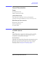
General Characteristics
Weight
Net: Approximately 9 kg
Shipping: Approximately 20 kg
Cabinet Dimensions
These dimensions exclude front and rear panel protrusions.
89 mm H by 425 mm W by 500 mm D (3.5 in by 16.75 in by 19.7 in)
Miscellaneous Characteristics
RF connectors: Type N female
Switch type: Mechanical
I/O Control: GPIB
Available Options
UK6
Option UK6 provides a commercial calibration certificate including
actual test data. Data includes test results including reflection,
transmission, and crosstalk for all test ports.
Rack Ear Mounts
Option 908, part number 5062-3974, provides rack mounts that make it
quick and easy to install or remove the test set from a mainframe.
For further information on these options, please contact Agilent
Technologies. Refer to Chapter 10 , “Contacting Agilent.”

1-8 Agilent Technologies Z5623A Option H48
Instrument Description
Cleaning and Shipping Instructions
Cleaning and Shipping Instructions
Cleaning
Clean the instrument cabinet using a damp cloth only.
Shipping
Always transport or ship the instrument using the original packaging if
possible. If not, comparable packaging must be used.

Agilent Technologies Z5623A Option H48 2 -1
2 Installation
This chapter contains the following sections:
• Checking the Shipment
• Recommended Additional Equipment
• Familiarization with Safety Requirements
• Electrical Preparations
• Environmental Preparations
• Test Set Familiarization
• Setting the GPIB Address of the Test Set
• Connecting and Turning on the Test Set

2 -2 Agilent Technologies Z5623A Option H48
Installation
Checking the Shipment
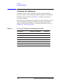
Checking the Shipment
After the test set has been unpacked, keep the original packaging
materials so they can be used if you need to transport the instrument.
Check the items received against Table 2-1 to make sure you have
received everything.
Inspect the test set and all accessories for any signs of damage that may
have occurred during shipment. If your test set or any accessories
appear to be damaged or missing, call Agilent Technologies. Refer to
Chapter 10 , “Contacting Agilent.”
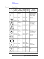
Table 2-1 Accessories Supplied with Z5623A Option H48
Description Agilent Part Number Quantity
Power Cord See Figure 2-2 on page 2-6 1
Front Handle Kit 5063-9226 1
Rack Mount Kit 5063-9232 1
RF Cable 8120-4782 2
GPIB Cable .5M HP 10833D 1
User’s and Service Guide Z5623-90016 1

Agilent Technologies Z5623A Option H48 2 -3
Installation
Recommended Additional Equipment
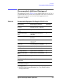
Recommended Additional Equipment
The equipment listed in Table 2-2 is not shipped with the test set, but is
recommended for use with it. The remainder of this User’s and Service
Guide assumes that the user has the listed equipment (or its
equivalent) available.
Table 2-2 Recommended Equipment Not Supplied With Test Set
Description Model Or Part Number Quantity
PNA Series Network
Analyzer
Agilent Model No.
E8356A, E8357A, or E8358A
1
Electronic Calibration
Module
Agilent Part No. 85072-60007 1
Keyboard with USB
cable
Hewlett-Packard Model No.
SK-2502U
a
1
Mouse with USB cable Hewlett-Packard Model No.
M-UB48
a
USB Quad Hub Peracom Model No.
UH4000A
a,b
1
USB Cable
Peracom Model No. CA2000A
a,b
1
RF Cable (24”)
Agilent Part No. 8120-4781
a
3
9/16” Wrench Agilent Part No. 8710-1770 1
3/4” Torque Wrench Agilent Part No. 8710-1766 1
Type N 50 Ohm Male
Short
Agilent Part No. 85032-60016 2
Type N 50 Ohm Female
Short
Agilent Part No. 85032-60015 2
Type N 50 Ohm Female
Termination
Agilent Part No. 85032-60018 2
Type N 50 Ohm
Female-Female Adapter
Agilent Part No. 85032-60021 1
a. Or equivalent
b. Available from Peracom Networks, Inc., Cary, North Carolina
(www.peracom.com).

2 -4 Agilent Technologies Z5623A Option H48
Installation
Familiarization with Safety Requirements
Familiarization with Safety Requirements
This document contains two types of safety notices: Warnings and
Cautions.
A Warning denotes a hazard that may endanger the operator.
A Caution denotes a hazard that may endanger the instrument.
Before proceeding to the Electrical Preparations described in the next
section, turn to Chapter 9, “Safety and Regulatory Information,” and
review the Warnings, Cautions, and safety markings that apply to this
instrument.
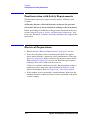
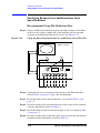
Electrical Preparations
1. Ensure that the “Electrical Requirements” on page 1-6 are met.
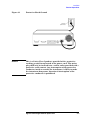
2. Verify that the power cable is not damaged and that the power
source outlet provides a protective earth ground contact. Note that
Figure 2-1 on page 2-5 depicts only one type of power source outlet.
Refer to Figure 2-2 on page 2-6 to see the different types of power
cord plugs that can be used with your test set.
Cables are available in different lengths. For descriptions and part
numbers of cables other than those described in Figure 2-2, call
Agilent Technologies. Refer to Chapter 10 , “Contacting Agilent.”
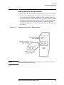
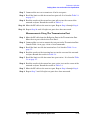
3. If this product is to be powered by autotransformer, make sure the
common terminal is connected to the neutral (grounded) side of the
ac power supply.
Page is loading ...
Page is loading ...
Page is loading ...
Page is loading ...
Page is loading ...
Page is loading ...
Page is loading ...
Page is loading ...
Page is loading ...
Page is loading ...
Page is loading ...
Page is loading ...
Page is loading ...
Page is loading ...
Page is loading ...
Page is loading ...
Page is loading ...
Page is loading ...
Page is loading ...
Page is loading ...
Page is loading ...
Page is loading ...
Page is loading ...
Page is loading ...
Page is loading ...
Page is loading ...
Page is loading ...
Page is loading ...
Page is loading ...
Page is loading ...
Page is loading ...
Page is loading ...
Page is loading ...
Page is loading ...
Page is loading ...
Page is loading ...
Page is loading ...
Page is loading ...
Page is loading ...
Page is loading ...
Page is loading ...
Page is loading ...
Page is loading ...
Page is loading ...
Page is loading ...
Page is loading ...
Page is loading ...
Page is loading ...
Page is loading ...
Page is loading ...
Page is loading ...
Page is loading ...
Page is loading ...
Page is loading ...
Page is loading ...
Page is loading ...
Page is loading ...
Page is loading ...
Page is loading ...
Page is loading ...
Page is loading ...
Page is loading ...
Page is loading ...
Page is loading ...
Page is loading ...
Page is loading ...
Page is loading ...
Page is loading ...
Page is loading ...
Page is loading ...
Page is loading ...
Page is loading ...
Page is loading ...
Page is loading ...
Page is loading ...
Page is loading ...
Page is loading ...
Page is loading ...
Page is loading ...
Page is loading ...
Page is loading ...
Page is loading ...
Page is loading ...
Page is loading ...
Page is loading ...
Page is loading ...
Page is loading ...
Page is loading ...
Page is loading ...
Page is loading ...
Page is loading ...
Page is loading ...
Page is loading ...
Page is loading ...
Page is loading ...
Page is loading ...
Page is loading ...
Page is loading ...
Page is loading ...
Page is loading ...
Page is loading ...
Page is loading ...
Page is loading ...
Page is loading ...
Page is loading ...
Page is loading ...
Page is loading ...
Page is loading ...
Page is loading ...
Page is loading ...
Page is loading ...
Page is loading ...
Page is loading ...
Page is loading ...
Page is loading ...
Page is loading ...
Page is loading ...
Page is loading ...
-
 1
1
-
 2
2
-
 3
3
-
 4
4
-
 5
5
-
 6
6
-
 7
7
-
 8
8
-
 9
9
-
 10
10
-
 11
11
-
 12
12
-
 13
13
-
 14
14
-
 15
15
-
 16
16
-
 17
17
-
 18
18
-
 19
19
-
 20
20
-
 21
21
-
 22
22
-
 23
23
-
 24
24
-
 25
25
-
 26
26
-
 27
27
-
 28
28
-
 29
29
-
 30
30
-
 31
31
-
 32
32
-
 33
33
-
 34
34
-
 35
35
-
 36
36
-
 37
37
-
 38
38
-
 39
39
-
 40
40
-
 41
41
-
 42
42
-
 43
43
-
 44
44
-
 45
45
-
 46
46
-
 47
47
-
 48
48
-
 49
49
-
 50
50
-
 51
51
-
 52
52
-
 53
53
-
 54
54
-
 55
55
-
 56
56
-
 57
57
-
 58
58
-
 59
59
-
 60
60
-
 61
61
-
 62
62
-
 63
63
-
 64
64
-
 65
65
-
 66
66
-
 67
67
-
 68
68
-
 69
69
-
 70
70
-
 71
71
-
 72
72
-
 73
73
-
 74
74
-
 75
75
-
 76
76
-
 77
77
-
 78
78
-
 79
79
-
 80
80
-
 81
81
-
 82
82
-
 83
83
-
 84
84
-
 85
85
-
 86
86
-
 87
87
-
 88
88
-
 89
89
-
 90
90
-
 91
91
-
 92
92
-
 93
93
-
 94
94
-
 95
95
-
 96
96
-
 97
97
-
 98
98
-
 99
99
-
 100
100
-
 101
101
-
 102
102
-
 103
103
-
 104
104
-
 105
105
-
 106
106
-
 107
107
-
 108
108
-
 109
109
-
 110
110
-
 111
111
-
 112
112
-
 113
113
-
 114
114
-
 115
115
-
 116
116
-
 117
117
-
 118
118
-
 119
119
-
 120
120
-
 121
121
-
 122
122
-
 123
123
-
 124
124
-
 125
125
-
 126
126
-
 127
127
-
 128
128
-
 129
129
-
 130
130
-
 131
131
-
 132
132
-
 133
133
-
 134
134
-
 135
135
-
 136
136
-
 137
137
-
 138
138


Agilent Technologies Option H48 Multiport Test Set Z5623A User manual
- Category
- Networking
- Type
- User manual
- This manual is also suitable for
Ask a question and I''ll find the answer in the document
Finding information in a document is now easier with AI
Related papers
-
Agilent Technologies 87020 User manual
-
-
-
-
-
-
-
-
Agilent Technologies ES User manual
-
Agilent Technologies 34450A User manual
Other documents
-
HP (Hewlett-Packard) Swimming Pool Gate Alarm Agilent 4194A User manual
-
HP 4278A User manual
-
-
Keysight PNA Series Network Analyzers Option 010 Time Domain Upgrade Kit Installation guide
-
Keysight Technologies PNA Series Installation And Getting Started Manual
-
-
-
Symmetricom 5071A Operating And Programming Manual
-
 Pendulum SCN Series User manual
-
