Page is loading ...

MUSTANG SURVIVAL INTEGRATED AIRCREW LIFE
PRESERVER AND SURVIVAL VEST,
MUSTANG MODEL MSV971
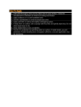
DESCRIPTION AND MAINTENANCE INSTRUCTIONS
JUNE 9, 2004, REV: 1.0
Mustang Survival Canada Mustang Survival-USA
3810 Jacombs Road 3870 Mustang Way
Richmond, BC, V6V 1Y6 Bellingham, WA
Tel: (604) 270-8631 Fax: (604) 270-0489 USA 98226
E-mail: [email protected]
Tel: (360) 676-1782 Fax: (360) 676-5014
WEB: www.mustangsurvival.com
E-mail: [email protected]

Mustang Survival MSV971 Life Preserver and Survival Vest
Description and Maintenance Instructions
9 June 2004, Rev: 1.0
TABLE OF CONTENTS
1.0 INTRODUCTION................................................................................................................. 1
1.1 GENERAL ..................................................................................................................................1
1.2 CONTACT ..................................................................................................................................1
1.3 RIGHTS RESERVED .................................................................................................................1
1.4 RESPONSIBILITIES...................................................................................................................1
2.0 FEATURES......................................................................................................................... 3
2.1 DESIGN AND CONSTRUCTION ...............................................................................................3
2.2 ASSEMBLED LP/SV ..................................................................................................................3
2.3 LIFE PRESERVER.....................................................................................................................4
2.4 INFLATABLE CELL ....................................................................................................................4
2.5 MANUAL CO
2
INFLATION DEVICE...........................................................................................6
2.6 BEADED CO
2
INFLATION HANDLE..........................................................................................6
2.7 ORAL INFLATOR .......................................................................................................................7
2.8 PROTECTIVE CONTAINER ......................................................................................................7
2.9 SURVIVAL VEST .......................................................................................................................8
2.10 RESCUE HARNESS SYSTEM...................................................................................................9
2.11 ADJUSTABLE WAIST BELT ......................................................................................................9
2.12 SIDE ADJUSTMENT STRAPS...................................................................................................9
2.13 BALLISTIC LINER ATTACHMENT POINTS ............................................................................10
2.14 OPERATION.............................................................................................................................10
3.0 DONNING AND PACKING INSTRUCTIONS.................................................................... 12
3.1 GENERAL ................................................................................................................................12
3.2 FOLDING AND PACKING INSTRUCTIONS............................................................................12
4.0 MAINTENANCE AND CARE ............................................................................................ 17
4.1 GENERAL ................................................................................................................................17
4.2 CLEANING ...............................................................................................................................17
4.3 TREATMENT AFTER IMMERSION .........................................................................................17
4.4 SERVICE LIFE .........................................................................................................................18
4.5 WORK AREA............................................................................................................................18
4.6 STORAGE ................................................................................................................................18
4.7 EQUIPMENT REQUIRED ........................................................................................................18
4.8 MAINTENANCE REPORTING .................................................................................................18
5.0 INSPECTION AND TESTING ........................................................................................... 19
5.1 REQUIREMENTS.....................................................................................................................19
5.2 PRE-FLIGHT AND POST-FLIGHT INSPECTION....................................................................19
5.3 VISUAL INSPECTION..............................................................................................................19
5.4 MAINTENANCE INSPECTION ................................................................................................20
5.5 INFLATION MANIFOLD VALVE TEST ....................................................................................21
5.6 ORAL INFLATOR VALVE TEST ..............................................................................................21
5.7 INFLATABLE CELL TEST........................................................................................................21
5.8 CO
2
INFLATION DEVICE TEST ..............................................................................................22
5.9 CO
2
CYLINDER INSPECTION AND WEIGHT TEST...............................................................22
6.0 REPAIRS .......................................................................................................................... 23
6.1 GENERAL ................................................................................................................................23
6.2 IDENTIFICATION OF DEFECTS .............................................................................................23
6.3 SURVIVAL VEST OR PROTECTIVE CONTAINER.................................................................23
i
T
T
h
h
i
i
s
s
d
d
o
o
c
c
u
u
m
m
e
e
n
n
t
t
i
i
s
s
f
f
o
o
r
r
i
i
n
n
f
f
o
o
r
r
m
m
a
a
t
t
i
i
o
o
n
n
p
p
u
u
r
r
p
p
o
o
s
s
e
e
s
s
o
o
n
n
l
l
y
y
.
.
I
I
t
t
i
i
s
s
n
n
o
o
t
t
a
a
c
c
o
o
n
n
t
t
r
r
o
o
l
l
l
l
e
e
d
d
d
d
o
o
c
c
u
u
m
m
e
e
n
n
t
t
a
a
n
n
d
d
m
m
a
a
y
y
n
n
o
o
t
t
b
b
e
e
c
c
o
o
n
n
s
s
i
i
d
d
e
e
r
r
e
e
d
d
c
c
u
u
r
r
r
r
e
e
n
n
t
t
w
w
h
h
e
e
n
n
p
p
r
r
i
i
n
n
t
t
e
e
d
d
.
.

Mustang Survival MSV971 Life Preserver and Survival Vest
Description and Maintenance Instructions
9 June 2004, Rev: 1.0
6.4 SEWING...................................................................................................................................23
6.5 ORAL INFLATOR VALVE ........................................................................................................27
7.0 SUMMARY........................................................................................................................ 30
8.0 PARTS LIST ..................................................................................................................... 30
TABLE OF FIGURES
Figure 1. Vest Sizes............................................................................................................................... 1
Figure 2. Component Locations (front view).......................................................................................... 3
Figure 3. Component Locations (rear view)........................................................................................... 4
Figure 4. Speed Lacing Loop System.................................................................................................... 5
Figure 5. Manual CO
2
Inflation Device – Non-Operated/Ready Position............................................... 6
Figure 6. Inside View of the LP/SV ........................................................................................................ 8
Figure 7. Component Locations – Inflated Cell...................................................................................... 11
Figure 8. Step a. Folding and Packing Instructions ............................................................................... 12
Figure 9. Steps b. to e. Folding and Packing Instructions...................................................................... 13
Figure 10. Step f. Folding and Packing Instructions .............................................................................. 14
Figure 11. Step h. Folding and Packing Instructions .............................................................................14
Figure 12. Step j. Folding and Packing Instructions............................................................................... 15
Figure 13. Step l. Folding and Packing Instructions............................................................................... 15
Figure 14. Step o. Folding and Packing Instructions .............................................................................16
Figure 15. Step o. Folding and Packing Instructions .............................................................................16
Figure 16. Equipment Required............................................................................................................. 18
Figure 17. Step a. Patching ................................................................................................................... 24
Figure 18. Step b. Patching ................................................................................................................... 25
Figure 19. Steps c., d. and e. Patching.................................................................................................. 26
Figure 20. Steps f. and g. Patching........................................................................................................ 26
Figure 21. Step a. Replace Inflatable Cell ............................................................................................. 28
Figure 22. Step f. Replace Inflatable Cell .............................................................................................. 28
Figure 23. Step g. Replace Inflatable Cell ............................................................................................. 29
Figure 24. Step h. Replace Inflatable Cell ............................................................................................. 29
Figure 25. MSV971 Survival Vest and Index Numbers.......................................................................... 31
Figure 26. Parts List for the MSV971 Survival Vest............................................................................... 32
Figure 27. MSV971 Inflatable Cell and Index Numbers......................................................................... 34
Figure 28. Parts List for the MSV971 Inflatable Cell.............................................................................. 34
Figure 29. MSV971 Protective Cover and Index Numbers .................................................................... 35
Figure 30. Parts List for the MSV971 Protective Cover ......................................................................... 35
ii
T
T
h
h
i
i
s
s
d
d
o
o
c
c
u
u
m
m
e
e
n
n
t
t
i
i
s
s
f
f
o
o
r
r
i
i
n
n
f
f
o
o
r
r
m
m
a
a
t
t
i
i
o
o
n
n
p
p
u
u
r
r
p
p
o
o
s
s
e
e
s
s
o
o
n
n
l
l
y
y
.
.
I
I
t
t
i
i
s
s
n
n
o
o
t
t
a
a
c
c
o
o
n
n
t
t
r
r
o
o
l
l
l
l
e
e
d
d
d
d
o
o
c
c
u
u
m
m
e
e
n
n
t
t
a
a
n
n
d
d
m
m
a
a
y
y
n
n
o
o
t
t
b
b
e
e
c
c
o
o
n
n
s
s
i
i
d
d
e
e
r
r
e
e
d
d
c
c
u
u
r
r
r
r
e
e
n
n
t
t
w
w
h
h
e
e
n
n
p
p
r
r
i
i
n
n
t
t
e
e
d
d
.
.

Mustang Survival MSV971 Life Preserver and Survival Vest
Description and Maintenance Instructions
9 June 2004, Rev: 1.0
1.0 INTRODUCTION
1.1 GENERAL
1.1.1
1.1.2
The MSV971 LP/SV comprises of an aircrew life preserver fully integrated with a survival vest.
The life preserver is universal in size and fit. The survival vest is designed in four sizes, in
order to be close fitting and adaptable to each individual user.
Figure 1. Vest Sizes
SIZE CHEST SIZE RANGE
SMALL
MEDIUM
LARGE
EXTRA LARGE
36 - 40 inches / 91 - 102 cm
40 - 44 inches / 102 - 112 cm
44 - 48 inches / 112 - 122 cm
48 - 52 inches / 122 - 132 cm
1.2 CONTACT
1.2.1 For further information concerning this manual or the LP/SV, contact:
Mustang Survival Corp.
3810 Jacombs Road
Richmond, BC, Canada
V6V 1Y6
Tel. (604) 270-8631
Fax (604) 270-0489
E-mail: [email protected]
WEB: www.mustangsurvival.com
1.3 RIGHTS RESERVED
1.3.1
1.3.2
1.3.3
1.4.1
1.4.2
GORE-TEX® is a registered trademark of W.L. Gore and Associates.
Velcro is a trademark of American Velcro Inc.
Nomex
®
is a registered trademark of DuPont.
1.4 RESPONSIBILITIES
The individual to whom the LP/SV is issued or assigned, following internal training, assumes
responsibility for pre and post use inspections and for returning the LP/SV to the Life Support
Equipment shop for periodic inspection and testing on required dates.
Each operational organization is responsible for the instruction and survival training of all
MSV971 users in the following:
a. Fitting and operation of the LP/SV.
1
T
T
h
h
i
i
s
s
d
d
o
o
c
c
u
u
m
m
e
e
n
n
t
t
i
i
s
s
f
f
o
o
r
r
i
i
n
n
f
f
o
o
r
r
m
m
a
a
t
t
i
i
o
o
n
n
p
p
u
u
r
r
p
p
o
o
s
s
e
e
s
s
o
o
n
n
l
l
y
y
.
.
I
I
t
t
i
i
s
s
n
n
o
o
t
t
a
a
c
c
o
o
n
n
t
t
r
r
o
o
l
l
l
l
e
e
d
d
d
d
o
o
c
c
u
u
m
m
e
e
n
n
t
t
a
a
n
n
d
d
m
m
a
a
y
y
n
n
o
o
t
t
b
b
e
e
c
c
o
o
n
n
s
s
i
i
d
d
e
e
r
r
e
e
d
d
c
c
u
u
r
r
r
r
e
e
n
n
t
t
w
w
h
h
e
e
n
n
p
p
r
r
i
i
n
n
t
t
e
e
d
d
.
.

Mustang Survival MSV971 Life Preserver and Survival Vest
Description and Maintenance Instructions
9 June 2004, Rev: 1.0
b. Purpose, use and operation of all LP/SV furnished equipment accessories.
c. Importance and method of visual pre and post use inspections.
The Aviation Life Support Equipment shop is responsible for: 1.4.3
1.4.4
1.4.5
a. Periodic inspection and testing of the LP/SV.
NOTE: The inspection interval should not exceed 180 days (see section 5.0).
b. Inspection when first issued from a Supply Depot or contractor and prior to issue for
service.
c. Maintenance, cleaning, and repair if and when required.
d. Ensuring that a fully charged carbon dioxide (CO
2
) cylinder and functional CO
2
inflation device are properly installed prior to issue.
e. Requisitioning and maintaining stocks of spare parts.
f. Maintenance of inspection records of all MSV971 units.
Testing
1.4.4.1 All LP/SV’s are tested to ensure the highest level of reliability and performance. Mustang
Survival offers superior quality under rigid QA standards which are certified to ISO-9001.
Fit
1.4.5.1 When an MSV971 unit is initially issued to aircrew personnel, assigned to an aircraft
passenger, or seasonal environments dictate the changing of personnel flight clothing it is to
be individually fitted to the wearer. The wearer is to be fully instructed in the donning and
adjustment procedures.
2
T
T
h
h
i
i
s
s
d
d
o
o
c
c
u
u
m
m
e
e
n
n
t
t
i
i
s
s
f
f
o
o
r
r
i
i
n
n
f
f
o
o
r
r
m
m
a
a
t
t
i
i
o
o
n
n
p
p
u
u
r
r
p
p
o
o
s
s
e
e
s
s
o
o
n
n
l
l
y
y
.
.
I
I
t
t
i
i
s
s
n
n
o
o
t
t
a
a
c
c
o
o
n
n
t
t
r
r
o
o
l
l
l
l
e
e
d
d
d
d
o
o
c
c
u
u
m
m
e
e
n
n
t
t
a
a
n
n
d
d
m
m
a
a
y
y
n
n
o
o
t
t
b
b
e
e
c
c
o
o
n
n
s
s
i
i
d
d
e
e
r
r
e
e
d
d
c
c
u
u
r
r
r
r
e
e
n
n
t
t
w
w
h
h
e
e
n
n
p
p
r
r
i
i
n
n
t
t
e
e
d
d
.
.

Mustang Survival MSV971 Life Preserver and Survival Vest
Description and Maintenance Instructions
9 June 2004, Rev: 1.0
2.0 FEATURES
2.1 DESIGN AND CONSTRUCTION
General 2.1.1
2.1.2
2.1.1.1 Mustang Survival personal LP/SV’s are designed to provide flotation in case of accidental
immersion in water, minimizing the risk of drowning.
Familiarize yourself with all the features of the LP/SV to maximize its effectiveness.
Illustrations are provided to support the text.
NOTE: All location reference points in this section are based from the perspective of
the person wearing the LP/SV.
2.2 ASSEMBLED LP/SV
Figure 2. Component Locations (front view)
Survival Vest Inflatable Life
Preserver
(stowed)
Front Entry Zipper
Adjustable Waist Belt
Entry Zipper Snap Tab
Storage Pocket
Storage Pocket
D-rings
Side Adjustment Strap
Storage Pocket
Waist Buckle
3
T
T
h
h
i
i
s
s
d
d
o
o
c
c
u
u
m
m
e
e
n
n
t
t
i
i
s
s
f
f
o
o
r
r
i
i
n
n
f
f
o
o
r
r
m
m
a
a
t
t
i
i
o
o
n
n
p
p
u
u
r
r
p
p
o
o
s
s
e
e
s
s
o
o
n
n
l
l
y
y
.
.
I
I
t
t
i
i
s
s
n
n
o
o
t
t
a
a
c
c
o
o
n
n
t
t
r
r
o
o
l
l
l
l
e
e
d
d
d
d
o
o
c
c
u
u
m
m
e
e
n
n
t
t
a
a
n
n
d
d
m
m
a
a
y
y
n
n
o
o
t
t
b
b
e
e
c
c
o
o
n
n
s
s
i
i
d
d
e
e
r
r
e
e
d
d
c
c
u
u
r
r
r
r
e
e
n
n
t
t
w
w
h
h
e
e
n
n
p
p
r
r
i
i
n
n
t
t
e
e
d
d
.
.

Mustang Survival MSV971 Life Preserver and Survival Vest
Description and Maintenance Instructions
9 June 2004, Rev: 1.0
Figure 3. Component Locations (rear view)
Velcro Tab
Adjustable Waist Belt
Storage Pocket
Protective
Container
Attachment Tab
Life Preserver
Survival Vest
Side Adjustment Strap
Storage Pocket
Two-piece Buckle
2.3 LIFE PRESERVER
2.3.1
2.3.2
2.4.1
2.4.2
The life preserver cover (see figure 29) is attached directly to the survival vest with an
interlocking (Dutch style) speed lacing loop system (see figure 4) and is easily removable. The
life preserver consists of two major components:
a. Inflatable Cell
b. Protective Container
The inflatable cell is attached to the Survival Vest at three points; one directly to the protective
container by means of a short speed lacing loop system at the rear. The other two direct
attachment points are where the webbing straps attach to the front lobes. The free end of the
Survival Vest anchor strap passes through the slots on the back side the protective cover and
through the inflatable cell grommets (1.0 inch (25 mm) plastic grommets RF bonded in place),
located at the lower points of the cell lobes. A ‘lift the dot’ snap is used to secure them in
place. The inflatable cell, when folded, is contained within the protective container by means of
a perimeter zipper closure system and a Velcro patch located at the rear at the zipper ends.
2.4 INFLATABLE CELL
The inflatable cell is made from polyurethane coated nylon fabric and is yellow in colour. The
perimeter of the cell is sealed using radio frequency (RF) bonding.
NOTE: All location reference points in this section are based from the perspective of
the person wearing the LP/SV.
The inflatable cell comprises two independent chambers, front and rear, which are created by
the provision of a separate ply of unsupported polyurethane film between the outer panels of
4
T
T
h
h
i
i
s
s
d
d
o
o
c
c
u
u
m
m
e
e
n
n
t
t
i
i
s
s
f
f
o
o
r
r
i
i
n
n
f
f
o
o
r
r
m
m
a
a
t
t
i
i
o
o
n
n
p
p
u
u
r
r
p
p
o
o
s
s
e
e
s
s
o
o
n
n
l
l
y
y
.
.
I
I
t
t
i
i
s
s
n
n
o
o
t
t
a
a
c
c
o
o
n
n
t
t
r
r
o
o
l
l
l
l
e
e
d
d
d
d
o
o
c
c
u
u
m
m
e
e
n
n
t
t
a
a
n
n
d
d
m
m
a
a
y
y
n
n
o
o
t
t
b
b
e
e
c
c
o
o
n
n
s
s
i
i
d
d
e
e
r
r
e
e
d
d
c
c
u
u
r
r
r
r
e
e
n
n
t
t
w
w
h
h
e
e
n
n
p
p
r
r
i
i
n
n
t
t
e
e
d
d
.
.

Mustang Survival MSV971 Life Preserver and Survival Vest
Description and Maintenance Instructions
9 June 2004, Rev: 1.0
the cell. This ply forms a floating baffle, which is free to move between the front and rear
panels depending on the gas volume in each chamber.
WARNING: The MSV971 is configured with a manual inflation system and will not
automatically inflate when immersed in water.
2.4.3
2.4.4
2.4.5
Normal manual inflation by carbon dioxide gas (CO
2
), fully inflates the rear chamber. The front
chamber may be inflated by mouth only, and provides for redundancy in an event where the
rear chamber becomes damaged or requires topping up.
When inflated, the cell forms a yoke around the back of the user's neck, extending into two
lobes down the user's chest.
A cell anchor strip is permanently attached to the rear panel of the inflatable cell to permit
attachment of the cell to the protective container by means of an interlocking (Dutch style)
speed lacing loop system.
Figure 4. Speed Lacing Loop System
Aramid Cord Loops
Grommets
Anchor Panel Lacing Anchor Loop Self-Locking Tie
2.4.6 The inflatable cell is designed to provide a minimum buoyant force of 15.9 kg (35 lb), when
fully inflated with 34-37 grams of carbon dioxide (CO
2
) gas in ambient temperatures above 0°
C (32° F).
5
T
T
h
h
i
i
s
s
d
d
o
o
c
c
u
u
m
m
e
e
n
n
t
t
i
i
s
s
f
f
o
o
r
r
i
i
n
n
f
f
o
o
r
r
m
m
a
a
t
t
i
i
o
o
n
n
p
p
u
u
r
r
p
p
o
o
s
s
e
e
s
s
o
o
n
n
l
l
y
y
.
.
I
I
t
t
i
i
s
s
n
n
o
o
t
t
a
a
c
c
o
o
n
n
t
t
r
r
o
o
l
l
l
l
e
e
d
d
d
d
o
o
c
c
u
u
m
m
e
e
n
n
t
t
a
a
n
n
d
d
m
m
a
a
y
y
n
n
o
o
t
t
b
b
e
e
c
c
o
o
n
n
s
s
i
i
d
d
e
e
r
r
e
e
d
d
c
c
u
u
r
r
r
r
e
e
n
n
t
t
w
w
h
h
e
e
n
n
p
p
r
r
i
i
n
n
t
t
e
e
d
d
.
.

Mustang Survival MSV971 Life Preserver and Survival Vest
Description and Maintenance Instructions
9 June 2004, Rev: 1.0
2.5 MANUAL CO
2
INFLATION DEVICE
The MSV971 is an appropriate platform for a wide variety of customized LP/SV units to address user
requirements that include:
• use in ejection seat fitted aircraft
• use with an automation inflation device
• stowage of unique pieces/combinations of survival equipment
Contact Mustang Survival for further details.
2.5.1 Life preservers, which are intended for use in non-ejection seat, equipped aircraft incorporate
a manually operated inflation device. The operating components of the manual inflation device
(Halkey-Roberts HD77189 840 AMLS INFLATOR) are shown in figure 5.
Figure 5. Manual CO
2
Inflation Device – Non-Operated/Ready Position
CO2 Cylinder
Manual Inflator
Lever in Up and
Read
y
Position
Green Indicator Pin
Pull-tab
2.5.2
2.6.1
The manual inflation device is located on the rear left lobe of the inflatable cell. The inflation
device is secured with a cap nut to the manifold valve, which in turn is RF bonded to the
inflatable cell. A 34-37 gram carbon dioxide (CO
2
) cylinder is threaded into the top of the
inflation device, and is secured against the cell with a looped nylon elastic retaining strap. The
beaded inflation handle is attached with a lanyard to the operating lever of the inflation device,
which in turn is safety tied by inserting and tying a red cotton witness thread through the hole
in the operating lever and through the hole in the body of the inflation device.
2.6 BEADED CO
2
INFLATION HANDLE
The beaded inflation handle is constructed of six plastic beads threaded onto a loop of nylon
webbing. The handle is attached with a lanyard to the operating lever of the CO
2
inflation
device and is fixed with Velcro™ to the back side of the left lobe of the protective container.
6
T
T
h
h
i
i
s
s
d
d
o
o
c
c
u
u
m
m
e
e
n
n
t
t
i
i
s
s
f
f
o
o
r
r
i
i
n
n
f
f
o
o
r
r
m
m
a
a
t
t
i
i
o
o
n
n
p
p
u
u
r
r
p
p
o
o
s
s
e
e
s
s
o
o
n
n
l
l
y
y
.
.
I
I
t
t
i
i
s
s
n
n
o
o
t
t
a
a
c
c
o
o
n
n
t
t
r
r
o
o
l
l
l
l
e
e
d
d
d
d
o
o
c
c
u
u
m
m
e
e
n
n
t
t
a
a
n
n
d
d
m
m
a
a
y
y
n
n
o
o
t
t
b
b
e
e
c
c
o
o
n
n
s
s
i
i
d
d
e
e
r
r
e
e
d
d
c
c
u
u
r
r
r
r
e
e
n
n
t
t
w
w
h
h
e
e
n
n
p
p
r
r
i
i
n
n
t
t
e
e
d
d
.
.

Mustang Survival MSV971 Life Preserver and Survival Vest
Description and Maintenance Instructions
9 June 2004, Rev: 1.0
The beaded handle is designed to provide a positive grip for inflation of the preserver with
cold, wet or gloved hands.
2.7 ORAL INFLATOR
2.7.1
2.7.2
2.7.3
2.7.4
2.8.1
2.8.2
2.8.3
2.8.4
2.8.5
Two oral inflator valve assemblies are attached to the inflatable cell. Each oral inflator valve
assembly consists of an oral inflation valve mounted in an oral inflation tube, which in turn is
RF bonded to the inflatable cell. Both oral inflators are secured against the cell with a Velcro™
retaining strap. Each oral inflator accesses a separate chamber.
The oral inflator located on the front left lobe of the inflatable cell inflates/deflates the front
chamber. This inflator is used in the event that the rear inflatable chamber becomes damaged
or if the other chamber fails to inflate. When the inflatable cell is stored (packed), this inflator
valve is locked in the open position for use as back-up in an emergency.
The oral inflator located on the rear right lobe of the inflatable cell inflates/deflates the rear
inflatable chamber. This inflator provides an alternate means of inflation in the unlikely event
that the manual or automatic inflation device malfunctions. When the inflatable cell is stored
(packed), this inflator valve is locked in the closed position to prevent venting during inflation.
Both inflators also provide a means of "topping up" the cell to compensate for normal leakage
or under-inflation due to excessively cold temperatures. As well, these oral inflators provide a
means for cell deflation.
2.8 PROTECTIVE CONTAINER
The protective container is constructed of flame retardant aramid Nomex
®
cloth, sage green in
color. It is attached directly to the survival vest with a speed lacing loop system. The container
houses the inflatable cell, providing a compact, flame resistant protective enclosure.
The un-inflated cell is attached directly to the inside of the protective container with a speed
lacing loop system. The cell is neatly folded and packed within the container, which in turn is
secured in the closed position with a system of slide fasteners, and a Velcro™ tab. The tail
ends of the slide fastener tapes are protected by 'tucking' the tails into the lower openings of
the secured container to prevent premature opening.
The container’s slide fastener closure is closed with separate sliders, which are stowed and
secured with a lanyard inside the pockets located on the inside of the survival vest.
The inflation handle lanyard passes through the upper reinforced opening at the rear left of the
container and Velcro™ attaches the beaded inflation handle to the underside of the protective
container. The anchor straps for the lobes of the inflatable cell pass through the lower
reinforced openings in the protective container.
Inflation of the life preserver, forces the fasteners around the periphery of the container to
separate, allowing the cell to reach its fully inflated shape.
7
T
T
h
h
i
i
s
s
d
d
o
o
c
c
u
u
m
m
e
e
n
n
t
t
i
i
s
s
f
f
o
o
r
r
i
i
n
n
f
f
o
o
r
r
m
m
a
a
t
t
i
i
o
o
n
n
p
p
u
u
r
r
p
p
o
o
s
s
e
e
s
s
o
o
n
n
l
l
y
y
.
.
I
I
t
t
i
i
s
s
n
n
o
o
t
t
a
a
c
c
o
o
n
n
t
t
r
r
o
o
l
l
l
l
e
e
d
d
d
d
o
o
c
c
u
u
m
m
e
e
n
n
t
t
a
a
n
n
d
d
m
m
a
a
y
y
n
n
o
o
t
t
b
b
e
e
c
c
o
o
n
n
s
s
i
i
d
d
e
e
r
r
e
e
d
d
c
c
u
u
r
r
r
r
e
e
n
n
t
t
w
w
h
h
e
e
n
n
p
p
r
r
i
i
n
n
t
t
e
e
d
d
.
.

Mustang Survival MSV971 Life Preserver and Survival Vest
Description and Maintenance Instructions
9 June 2004, Rev: 1.0
2.9 SURVIVAL VEST
2.9.1 The Survival Vest is designed for use in fixed seat equipped aircraft, providing a mounting
platform for the life preserver equipped with a manual inflation device.
Figure 6. Inside View of the LP/SV
Ballistic Liner Attachment Tab
ID Label
LP Container
Closure Slider
Grommet
Ballistic Liner
Attachment
Zipper
Front Entry Zipper
Storage Pockets
The survival vest is a waistcoat style vest constructed of sage green, flame retardant, Nomex
®
cloth and mesh. The vest incorporates six outside pockets and four inside pockets, for the
stowage of personal survival equipment. Customers may contact Mustang Survival to select
different pocket configurations.
2.9.2
2.9.3
2.9.4
2.9.5
Also provided are two rings located on the front of the vest, between the lobes of the protective
container. These rings are meant to provide a suitable attachment point for reducing the
hanging weight of mask/helmet-mounted equipment (i.e. chemical protective canisters)
relieving stress to the neck.
The vest is donned and secured at the front with a large black nylon entry zipper and a waist
buckle. A snap tab is provided at the top, to retain the zipper slider tab and, to ensure that the
zipper remains secured in windblasts. The waist belt and side adjustment straps provide
adjustment.
A series of life preserver attachment loops, constructed of loops of sage green, fire retardant
Nomex
®
cord, are sewn into a folded nylon tape strip, which is secured down the front left and
front right chest area, and across the upper back, below the neck. These loops provide a
means for attachment of the life preserver protective container.
8
T
T
h
h
i
i
s
s
d
d
o
o
c
c
u
u
m
m
e
e
n
n
t
t
i
i
s
s
f
f
o
o
r
r
i
i
n
n
f
f
o
o
r
r
m
m
a
a
t
t
i
i
o
o
n
n
p
p
u
u
r
r
p
p
o
o
s
s
e
e
s
s
o
o
n
n
l
l
y
y
.
.
I
I
t
t
i
i
s
s
n
n
o
o
t
t
a
a
c
c
o
o
n
n
t
t
r
r
o
o
l
l
l
l
e
e
d
d
d
d
o
o
c
c
u
u
m
m
e
e
n
n
t
t
a
a
n
n
d
d
m
m
a
a
y
y
n
n
o
o
t
t
b
b
e
e
c
c
o
o
n
n
s
s
i
i
d
d
e
e
r
r
e
e
d
d
c
c
u
u
r
r
r
r
e
e
n
n
t
t
w
w
h
h
e
e
n
n
p
p
r
r
i
i
n
n
t
t
e
e
d
d
.
.

Mustang Survival MSV971 Life Preserver and Survival Vest
Description and Maintenance Instructions
9 June 2004, Rev: 1.0
2.10 RESCUE HARNESS SYSTEM
2.10.1
2.10.2
2.10.3
2.10.4
2.10.5
2.11.1
2.11.2
2.11.3
2.11.4
2.12.1
2.12.2
2.12.3
The vest incorporates a rescue harness system, consisting of a left side and right side harness
handle loop. The harnesses are sewn directly to the outside of the vest, and are constructed of
sage green nylon webbing, folded and stitched over a stainless steel reinforcement cable
which is used only to maintain the loop shape of the harness. Both sides should be used
simultaneously during lifting.
The side adjustment straps are located on the left and right sides of the survival vest, just
below the arm openings. The side adjustment straps provide both preliminary and final wearer
adjustment for use, both prior to and after water entry.
The harness handle loops are fed through the upper reinforced slot opening in the protective
container and stored underneath the folded cell. Velcro™ deployment lines attach the top of
each handle loop that attaches to the inflatable cell so that the lines are readily accessible
after inflation.
WARNING: Failure to do this will cause the harness system to be inoperative and could
only be used after the inflatable cell has been deflated.
Each harness has a strip of reflective tape stitched to the top of it for low-light rescues..
The (user’s) right hand harness has an attached buddy-line and whistle. These items are
stored in two looped nylon retaining straps fixed mid-way up the harness.
2.11 ADJUSTABLE WAIST BELT
The waist belt is constructed of 1
1
/
2
inch (38 mm) wide sage green nylon webbing. The belt is
secured at the front of the vest with a two-piece steel buckle. The belt provides both
preliminary wearer adjustment upon donning the LP/SV and a final adjustment just before or
after water entry.
The waist belt is stitched directly to the vest at the front left and at the right side, effectively
separating the belt into two adjustment areas.
Preliminary fit by adjusting the belt sliders, located at the rear of the vest, until the vest feels
comfortably snug.
Final/ongoing adjustment is accomplished by adjusting the buckle on the front of the belt after
donning. This adjustment is intended to ensure that the LP/SV remains well secured to the
wearer, reducing the potential for the vest to 'ride-up' on the wearer upon inflation of the life
preserver in water. Final adjustments are possible both prior to and after water entry.
2.12 SIDE ADJUSTMENT STRAPS
The side adjustment straps are constructed of one inch (25 mm) wide sage green acetyl nylon
webbing. One length of webbing forms the rear fixed ends, by looping through black nylon belt
adjusters, and sewing both free ends directly to the side of the vest.
Two lengths of webbing form the adjustment ends; with one end sewn to the front of the vest
and the free end passed through a nylon belt loop and looped through the belt adjuster, then is
folded and sewn into a T-tab for webbing retention.
Adjust by pulling on the T-tab. Loosen by lifting at the front of the nylon adjuster and pushing
the adjuster rearwards.
9
T
T
h
h
i
i
s
s
d
d
o
o
c
c
u
u
m
m
e
e
n
n
t
t
i
i
s
s
f
f
o
o
r
r
i
i
n
n
f
f
o
o
r
r
m
m
a
a
t
t
i
i
o
o
n
n
p
p
u
u
r
r
p
p
o
o
s
s
e
e
s
s
o
o
n
n
l
l
y
y
.
.
I
I
t
t
i
i
s
s
n
n
o
o
t
t
a
a
c
c
o
o
n
n
t
t
r
r
o
o
l
l
l
l
e
e
d
d
d
d
o
o
c
c
u
u
m
m
e
e
n
n
t
t
a
a
n
n
d
d
m
m
a
a
y
y
n
n
o
o
t
t
b
b
e
e
c
c
o
o
n
n
s
s
i
i
d
d
e
e
r
r
e
e
d
d
c
c
u
u
r
r
r
r
e
e
n
n
t
t
w
w
h
h
e
e
n
n
p
p
r
r
i
i
n
n
t
t
e
e
d
d
.
.

Mustang Survival MSV971 Life Preserver and Survival Vest
Description and Maintenance Instructions
9 June 2004, Rev: 1.0
2.13 BALLISTIC LINER ATTACHMENT POINTS
2.13.1
2.14.1
The MSV971 has built-in provisions for adding an optional ballistic liner accessory to the inside
of the survival vest. The vest has two zippers running along the inside of the main opening and
a Velcro™ tab at the inner neck that secure the ballistic liner.
NOTE: Depending on the thickness of the liner used, switching to a larger sized
survival vest may be necessary when worn with a ballistic liner.
2.14 OPERATION
CAUTION: Over-pressurization will over-stress the inflatable cell. Both chambers of the
cell must be completely evacuated of any residual air or carbon dioxide gas
prior to CO
2
inflation.
Manual operation of the life preserver is accomplished by grasping the beaded inflation handle
located on the lower left side of the protective container. Jerking sharply downwards rotates
the operating lever of the CO
2
inflation device, which in turn forces the piercing pin to puncture
the neck of the CO
2
cylinder and allow the compressed gas to flow into the inflatable cell.
The MSV971 is an appropriate platform for a wide variety of customized LP/SV units to address user
requirements that include:
• use in ejection seat fitted aircraft
• use with an automation inflation device
• stowage of unique pieces/combinations of survival equipment
Contact Mustang Survival for further details.
10
T
T
h
h
i
i
s
s
d
d
o
o
c
c
u
u
m
m
e
e
n
n
t
t
i
i
s
s
f
f
o
o
r
r
i
i
n
n
f
f
o
o
r
r
m
m
a
a
t
t
i
i
o
o
n
n
p
p
u
u
r
r
p
p
o
o
s
s
e
e
s
s
o
o
n
n
l
l
y
y
.
.
I
I
t
t
i
i
s
s
n
n
o
o
t
t
a
a
c
c
o
o
n
n
t
t
r
r
o
o
l
l
l
l
e
e
d
d
d
d
o
o
c
c
u
u
m
m
e
e
n
n
t
t
a
a
n
n
d
d
m
m
a
a
y
y
n
n
o
o
t
t
b
b
e
e
c
c
o
o
n
n
s
s
i
i
d
d
e
e
r
r
e
e
d
d
c
c
u
u
r
r
r
r
e
e
n
n
t
t
w
w
h
h
e
e
n
n
p
p
r
r
i
i
n
n
t
t
e
e
d
d
.
.

Mustang Survival MSV971 Life Preserver and Survival Vest
Description and Maintenance Instructions
9 June 2004, Rev: 1.0
2.14.2 The pressure of the expanding gas forces the fasteners around the periphery of the protective
container to separate, automatically opening the protective container and allowing the cell to
reach its fully inflated shape.
NOTE: Carbon dioxide gas does not remain in the life preserver indefinitely. Either of
the oral inflator valves can be used as a means of compensating for normal cell
leakage. The oral inflators are also provided as an emergency back up in the
unlikely event that the CO
2
inflation device fails.
Figure 7. Component Locations – Inflated Cell
Reflective Tape
Survival Vest
Rescue Harness
Deployment Line
Protective Container
Inflatable Cell
Oral Inflator
Retaining Strap
Oral Inflation
Assembly (Front
Chamber)
11
T
T
h
h
i
i
s
s
d
d
o
o
c
c
u
u
m
m
e
e
n
n
t
t
i
i
s
s
f
f
o
o
r
r
i
i
n
n
f
f
o
o
r
r
m
m
a
a
t
t
i
i
o
o
n
n
p
p
u
u
r
r
p
p
o
o
s
s
e
e
s
s
o
o
n
n
l
l
y
y
.
.
I
I
t
t
i
i
s
s
n
n
o
o
t
t
a
a
c
c
o
o
n
n
t
t
r
r
o
o
l
l
l
l
e
e
d
d
d
d
o
o
c
c
u
u
m
m
e
e
n
n
t
t
a
a
n
n
d
d
m
m
a
a
y
y
n
n
o
o
t
t
b
b
e
e
c
c
o
o
n
n
s
s
i
i
d
d
e
e
r
r
e
e
d
d
c
c
u
u
r
r
r
r
e
e
n
n
t
t
w
w
h
h
e
e
n
n
p
p
r
r
i
i
n
n
t
t
e
e
d
d
.
.

Mustang Survival MSV971 Life Preserver and Survival Vest
Description and Maintenance Instructions
9 June 2004, Rev: 1.0
3.0 DONNING AND PACKING INSTRUCTIONS
3.1 GENERAL
WARNING: The MSV971 must be worn fully assembled. The modules are not to be worn
separately. A loss of protection and wear resistance may result if worn
improperly.
3.2 FOLDING AND PACKING INSTRUCTIONS
3.2.1 To fold and pack the MSV971:
NOTE: Points of reference (in this section) for folding and packing are based from the
perspective of person facing the front of an LP/SV.
a. Remove the zipper closing sliders from inside the inner front pockets of the survival
vest.
Figure 8. Step a. Folding and Packing Instructions
Zipper Slider
12
T
T
h
h
i
i
s
s
d
d
o
o
c
c
u
u
m
m
e
e
n
n
t
t
i
i
s
s
f
f
o
o
r
r
i
i
n
n
f
f
o
o
r
r
m
m
a
a
t
t
i
i
o
o
n
n
p
p
u
u
r
r
p
p
o
o
s
s
e
e
s
s
o
o
n
n
l
l
y
y
.
.
I
I
t
t
i
i
s
s
n
n
o
o
t
t
a
a
c
c
o
o
n
n
t
t
r
r
o
o
l
l
l
l
e
e
d
d
d
d
o
o
c
c
u
u
m
m
e
e
n
n
t
t
a
a
n
n
d
d
m
m
a
a
y
y
n
n
o
o
t
t
b
b
e
e
c
c
o
o
n
n
s
s
i
i
d
d
e
e
r
r
e
e
d
d
c
c
u
u
r
r
r
r
e
e
n
n
t
t
w
w
h
h
e
e
n
n
p
p
r
r
i
i
n
n
t
t
e
e
d
d
.
.

Mustang Survival MSV971 Life Preserver and Survival Vest
Description and Maintenance Instructions
9 June 2004, Rev: 1.0
b. Lay the LP/SV unit out on a flat, clean surface so that the completely deflated cell is
fully extended.
c. Ensure that the rescue harness loops are fed through the upper openings in the
protective container and laying flat underneath the cell. Check that the Velcro™
deployment lines are routed through the centre of the collar and connected the top of
the harness loops with the patch on the cell and also check that the buddy-line and
whistle are secured in place.
d. SIDE OPPOSITE TO MANIFOLD VALVE Screw shall be turned fully in the LOWER
(not locked) position. This would allow the user to, if needed, manually inflate the cell
without having to fumble with the lock.
e. MANIFOLD VALVE SIDE Screw shall be turned fully in the UPPER (locked)
position. Otherwise, as the cell is folded and packed and the inflator actuated, it is
possible that the cell itself may depress the valve as it inflates, permitting the escape
of gas.
Figure 9. Steps b. to e. Folding and Packing Instructions
Velcro™
deployment
lines for the
rescue harness
lifting straps
Side opposite
to manifold
valve
Zipper Closing
Sliders
Screw in
unlocked
position
13
T
T
h
h
i
i
s
s
d
d
o
o
c
c
u
u
m
m
e
e
n
n
t
t
i
i
s
s
f
f
o
o
r
r
i
i
n
n
f
f
o
o
r
r
m
m
a
a
t
t
i
i
o
o
n
n
p
p
u
u
r
r
p
p
o
o
s
s
e
e
s
s
o
o
n
n
l
l
y
y
.
.
I
I
t
t
i
i
s
s
n
n
o
o
t
t
a
a
c
c
o
o
n
n
t
t
r
r
o
o
l
l
l
l
e
e
d
d
d
d
o
o
c
c
u
u
m
m
e
e
n
n
t
t
a
a
n
n
d
d
m
m
a
a
y
y
n
n
o
o
t
t
b
b
e
e
c
c
o
o
n
n
s
s
i
i
d
d
e
e
r
r
e
e
d
d
c
c
u
u
r
r
r
r
e
e
n
n
t
t
w
w
h
h
e
e
n
n
p
p
r
r
i
i
n
n
t
t
e
e
d
d
.
.

Mustang Survival MSV971 Life Preserver and Survival Vest
Description and Maintenance Instructions
9 June 2004, Rev: 1.0
f. Ensure that the rescue harness lifting loops are fed through the upper openings in
the protective container and laying flat underneath the cell. Ensure that the buddy-
line and whistle are in place.
Figure 10. Step f. Folding and Packing Instructions
Harness
Loop
g. Attach a slider onto one side of the container-closing zipper at the bottom, and
carefully mate with the other zipper tail. Repeat for the other side.
h. Fold up the lower portion of the right side cell lobe so that the lower edge of the lobe
is within the protective container and fold in the sides of the cell lobe.
Figure 11. Step h. Folding and Packing Instructions
i. Ensuring the zipper does not snag the inflatable cell; ease the slider along the zipper,
progressively closing the container over the cell. Tuck the zipper tail inside the
opening at the lower edge of the protective container.
CAUTION: Ensure the lanyard is not wrapped around the inflator, or any other
component, that would prevent the operation of the inflator lever.
14
T
T
h
h
i
i
s
s
d
d
o
o
c
c
u
u
m
m
e
e
n
n
t
t
i
i
s
s
f
f
o
o
r
r
i
i
n
n
f
f
o
o
r
r
m
m
a
a
t
t
i
i
o
o
n
n
p
p
u
u
r
r
p
p
o
o
s
s
e
e
s
s
o
o
n
n
l
l
y
y
.
.
I
I
t
t
i
i
s
s
n
n
o
o
t
t
a
a
c
c
o
o
n
n
t
t
r
r
o
o
l
l
l
l
e
e
d
d
d
d
o
o
c
c
u
u
m
m
e
e
n
n
t
t
a
a
n
n
d
d
m
m
a
a
y
y
n
n
o
o
t
t
b
b
e
e
c
c
o
o
n
n
s
s
i
i
d
d
e
e
r
r
e
e
d
d
c
c
u
u
r
r
r
r
e
e
n
n
t
t
w
w
h
h
e
e
n
n
p
p
r
r
i
i
n
n
t
t
e
e
d
d
.
.

Mustang Survival MSV971 Life Preserver and Survival Vest
Description and Maintenance Instructions
9 June 2004, Rev: 1.0
j. Ensure (right side only) that the lanyard of the beaded handle passes through the
reinforced opening of the container.
NOTE: The inflator should be on top of the folded cell before closing to ensure
proper activation of the cylinder when the lanyard is pulled.
Figure 12. Step j. Folding and Packing Instructions
k. Repeat steps f. to i. for the left side of the inflatable cell.
l. Fold the cell into the top portion of the container, and continue to ease the slider
along up to the top centre where the zipper ends while keeping the cell in the
container. Don’t remove the slider yet.
Figure 13. Step l. Folding and Packing Instructions
15
T
T
h
h
i
i
s
s
d
d
o
o
c
c
u
u
m
m
e
e
n
n
t
t
i
i
s
s
f
f
o
o
r
r
i
i
n
n
f
f
o
o
r
r
m
m
a
a
t
t
i
i
o
o
n
n
p
p
u
u
r
r
p
p
o
o
s
s
e
e
s
s
o
o
n
n
l
l
y
y
.
.
I
I
t
t
i
i
s
s
n
n
o
o
t
t
a
a
c
c
o
o
n
n
t
t
r
r
o
o
l
l
l
l
e
e
d
d
d
d
o
o
c
c
u
u
m
m
e
e
n
n
t
t
a
a
n
n
d
d
m
m
a
a
y
y
n
n
o
o
t
t
b
b
e
e
c
c
o
o
n
n
s
s
i
i
d
d
e
e
r
r
e
e
d
d
c
c
u
u
r
r
r
r
e
e
n
n
t
t
w
w
h
h
e
e
n
n
p
p
r
r
i
i
n
n
t
t
e
e
d
d
.
.

Mustang Survival MSV971 Life Preserver and Survival Vest
Description and Maintenance Instructions
9 June 2004, Rev: 1.0
m. Secure the beaded inflation handle to the Velcro™ located on the underside of the
protective container, at the lower right.
n. Carefully remove the sliders from the zipper ends, and pinch together the Velcro™
tabs. Re-stow the sliders in the vest pockets.
o. Secure the beaded inflation handle to the Velcro™ located on the underside of the
protective container.
Figure 14. Step o. Folding and Packing Instructions
p. Flatten the top portion of the life preserver and mate the Velcro™ tab to the patch on
the back of the Survival Vest.
Figure 15. Step o. Folding and Packing Instructions
16
T
T
h
h
i
i
s
s
d
d
o
o
c
c
u
u
m
m
e
e
n
n
t
t
i
i
s
s
f
f
o
o
r
r
i
i
n
n
f
f
o
o
r
r
m
m
a
a
t
t
i
i
o
o
n
n
p
p
u
u
r
r
p
p
o
o
s
s
e
e
s
s
o
o
n
n
l
l
y
y
.
.
I
I
t
t
i
i
s
s
n
n
o
o
t
t
a
a
c
c
o
o
n
n
t
t
r
r
o
o
l
l
l
l
e
e
d
d
d
d
o
o
c
c
u
u
m
m
e
e
n
n
t
t
a
a
n
n
d
d
m
m
a
a
y
y
n
n
o
o
t
t
b
b
e
e
c
c
o
o
n
n
s
s
i
i
d
d
e
e
r
r
e
e
d
d
c
c
u
u
r
r
r
r
e
e
n
n
t
t
w
w
h
h
e
e
n
n
p
p
r
r
i
i
n
n
t
t
e
e
d
d
.
.

Mustang Survival MSV971 Life Preserver and Survival Vest
Description and Maintenance Instructions
9 June 2004, Rev: 1.0
4.0 MAINTENANCE AND CARE
4.1 GENERAL
4.1.1
4.2.1
4.3.1
4.3.2
4.3.3
After immersion in water (other than fresh clean water), the LP/SV modules should be either
washed or rinsed separately. To increase the life of the garment, it is recommended to wash
the LP/SV only when required.
4.2 CLEANING
Laundering Procedures
NOTE: Do not dry clean.
Do not use bleach or other chlorine products.
Do not use fabric softeners.
Do not tumble dry.
Do not iron.
Do not dry in front of a radiator or other source of direct heat.
Do not store in a wet condition.
a. Separate layers (Life Preserver and Survival Vest).
b. Ensure all pockets are emptied.
c. Hand wash or sponge down an area of the Life Preserver/Inflatable Cell fabric in
warm (100°F) soapy (using mild laundry detergent) fresh water, then rinse with clean
water. Do not completely immerse the Life Preserver/Inflatable Cell. If machine
washing the Survival Vest, use the gentle cycle with a mild detergent or soap.
d. Hang to dry the layers in a well-ventilated area, which is free from direct sunlight.
Ensure the Life Preserver and Survival Vest are completely dry before reassembling.
e. Reassemble the LP/SV.
4.2.1.1 To avoid mildew, hang dry the LP/SV after every use, and be sure not to stow the product
away while damp.
4.3 TREATMENT AFTER IMMERSION
Whenever a LP/SV has been immersed in water, it must be treated as specified below and
then inspected in accordance with the current authorized servicing schedule.
Fresh Water Immersion
4.3.2.1 Allow the LP/SV to dry naturally, preferably in the open air.
Salt Water Immersion
4.3.3.1 Disassemble the layers (Life Preserver and Survival Vest) and rinse thoroughly with clean,
fresh water. Allow the LP/SV modules to dry naturally, preferably in the open air.
17
T
T
h
h
i
i
s
s
d
d
o
o
c
c
u
u
m
m
e
e
n
n
t
t
i
i
s
s
f
f
o
o
r
r
i
i
n
n
f
f
o
o
r
r
m
m
a
a
t
t
i
i
o
o
n
n
p
p
u
u
r
r
p
p
o
o
s
s
e
e
s
s
o
o
n
n
l
l
y
y
.
.
I
I
t
t
i
i
s
s
n
n
o
o
t
t
a
a
c
c
o
o
n
n
t
t
r
r
o
o
l
l
l
l
e
e
d
d
d
d
o
o
c
c
u
u
m
m
e
e
n
n
t
t
a
a
n
n
d
d
m
m
a
a
y
y
n
n
o
o
t
t
b
b
e
e
c
c
o
o
n
n
s
s
i
i
d
d
e
e
r
r
e
e
d
d
c
c
u
u
r
r
r
r
e
e
n
n
t
t
w
w
h
h
e
e
n
n
p
p
r
r
i
i
n
n
t
t
e
e
d
d
.
.
/