
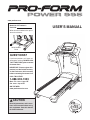
Serial Number
Decal
Model No. PFTL01299.2
Serial No.
Write the serial number in the space
above for reference.
CAUTION
Read all precautions and instruc-
tions in this manual before using
this equipment. Save this manual
for future reference.
QUESTIONS?
If you have questions, or if parts are
damaged or missing, DO NOT CON-
TACT THE STORE; please contact
Customer Care.
IMPORTANT: Please register this
product (see the limited warranty
on the back cover of this manual)
before contacting Customer Care.
CALL TOLL-FREE:
1-888-533-1333
Mon.–Fri. 6 a.m.–6 p.m. MT
Sat. 8 a.m.–4 p.m. MT
ON THE WEB:
www.proformservice.com
USERʼS MANUAL
www.proform.com

TABLE OF CONTENTS
WARNING DECAL PLACEMENT . . . . . . . . . . . . . . . . . . . . . . . . . . . . . . . . . . . . . . . . . . . . . . . . . . . . . . . . . . . . . .2
IMPORTANT PRECAUTIONS . . . . . . . . . . . . . . . . . . . . . . . . . . . . . . . . . . . . . . . . . . . . . . . . . . . . . . . . . . . . . . . .3
BEFORE YOU BEGIN . . . . . . . . . . . . . . . . . . . . . . . . . . . . . . . . . . . . . . . . . . . . . . . . . . . . . . . . . . . . . . . . . . . . . .5
A
SSEMBLY . . . . . . . . . . . . . . . . . . . . . . . . . . . . . . . . . . . . . . . . . . . . . . . . . . . . . . . . . . . . . . . . . . . . . . . . . . . . . . .6
OPERATION AND ADJUSTMENT . . . . . . . . . . . . . . . . . . . . . . . . . . . . . . . . . . . . . . . . . . . . . . . . . . . . . . . . . . . .14
HOW TO FOLD AND MOVE THE TREADMILL . . . . . . . . . . . . . . . . . . . . . . . . . . . . . . . . . . . . . . . . . . . . . . . . . .24
TROUBLESHOOTING . . . . . . . . . . . . . . . . . . . . . . . . . . . . . . . . . . . . . . . . . . . . . . . . . . . . . . . . . . . . . . . . . . . . .25
EXERCISE GUIDELINES . . . . . . . . . . . . . . . . . . . . . . . . . . . . . . . . . . . . . . . . . . . . . . . . . . . . . . . . . . . . . . . . . . .28
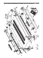
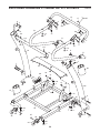
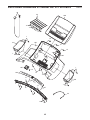
PART LIST . . . . . . . . . . . . . . . . . . . . . . . . . . . . . . . . . . . . . . . . . . . . . . . . . . . . . . . . . . . . . . . . . . . . . . . . . . . . . .30
EXPLODED DRAWING . . . . . . . . . . . . . . . . . . . . . . . . . . . . . . . . . . . . . . . . . . . . . . . . . . . . . . . . . . . . . . . . . . . .32
ORDERING REPLACEMENT PARTS . . . . . . . . . . . . . . . . . . . . . . . . . . . . . . . . . . . . . . . . . . . . . . . . . .Back Cover
LIMITED WARRANTY . . . . . . . . . . . . . . . . . . . . . . . . . . . . . . . . . . . . . . . . . . . . . . . . . . . . . . . . . . . . . .Back Cover
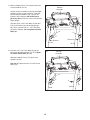
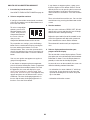
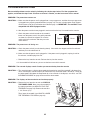
This drawing shows the locations
of the warning decals. If a decal
is missing or illegible, call the
telephone number on the front
cover of this manual and re-
quest a free replacement decal.
Apply the decal in the location
shown. Note: The decals may
not be shown at actual size.
WARNING DECAL PLACEMENT
2
PROFORM is a registered trademark of ICON IP, Inc.

3
1. Before beginning any exercise program, con-
sult your physician. This is especially impor-
tant for persons over age 35 or persons with
pre-existing health problems.
2. It is the responsibility of the owner to ensure
that all users of this treadmill are adequately
informed of all warnings and precautions.
3. Use the treadmill only as described.
4. Place the treadmill on a level surface, with at
least 8 ft. (2.4 m) of clearance behind it and 2
ft. (0.6 m) on each side. Do not place the
treadmill on any surface that blocks air open-
ings. To protect the floor or carpet from dam-
age, place a mat under the treadmill.
5. Keep the treadmill indoors, away from mois-
ture and dust. Do not put the treadmill in a
garage or covered patio, or near water.
6. Do not operate the treadmill where aerosol
products are used or where oxygen is being
administered.
7. Keep children under age 12 and pets away
from the treadmill at all times.
8. The treadmill should be used only by persons
weighing 350 lbs. (159 kg) or less.
9. Never allow more than one person on the
treadmill at a time.
10. Wear appropriate exercise clothes while
using the treadmill. Do not wear loose clothes
that could become caught in the treadmill.
Athletic support clothes are recommended
for both men and women. Always wear ath-
letic shoes. Never use the treadmill with bare
feet, wearing only stockings, or in sandals.
11. When connecting the power cord (see page
14), plug the power cord into a surge sup-
pressor (not included) and plug the surge
suppressor into a grounded circuit capable of
carrying 15 or more amps. No other appliance
should be on the same circuit. Do not use an
extension cord.
12. Use only a single-outlet surge suppressor that
meets all of the specifications described on
page 14. To purchase a surge suppressor, see
your local PROFORM dealer or call the tele-
phone number on the front cover of this man-
ual and order part number 146148, or see your
local electronics store.
13. Failure to use a properly functioning surge
suppressor could result in damage to the con-
trol system of the treadmill. If the control sys-
tem is damaged, the walking belt may slow,
accelerate, or stop unexpectedly, which may
result in a fall and serious injury.
14. Keep the power cord and the surge suppres-
sor away from heated surfaces.
15. Never move the walking belt while the power
is turned off. Do not operate the treadmill if
the power cord or plug is damaged, or if the
treadmill is not working properly. (See TROU-
BLESHOOTING on page 25 if the treadmill is
not working properly.)
16. Read, understand, and test the emergency
stop procedure before using the treadmill (see
HOW TO TURN ON THE POWER on page 16).
17. Never start the treadmill while you are stand-
ing on the walking belt. Always hold the
handrails while using the treadmill.
18. The treadmill is capable of high speeds.
Adjust the speed in small increments to avoid
sudden jumps in speed.
19. The pulse sensor is not a medical device.
Various factors, including the user's move-
ment, may affect the accuracy of heart rate
readings. The pulse sensor is intended only
as an exercise aid in determining heart rate
trends in general.
WARNING: To reduce the risk of serious injury, read all important precautions and in-
s
tructions in this manual and all warnings on your treadmill before using your treadmill. ICON as-
sumes no responsibility for personal injury or property damage sustained by or through the use of
this product.
IMPORTANT PRECAUTIONS

4
2
0. Never leave the treadmill unattended while it
is running. Always remove the key, unplug
the power cord, and press the power switch
into the off position when the treadmill is not
in use. (See the drawing on page 5 for the lo-
cation of the power switch.)
21. Do not attempt to raise, lower, or move the
treadmill until it is properly assembled. (See
ASSEMBLY on page 6, and HOW TO FOLD
AND MOVE THE TREADMILL on page 24.)
You must be able to safely lift 45 lbs. (20 kg)
to raise, lower, or move the treadmill.
22. When folding or moving the treadmill, make
sure that the storage latch is holding the
frame securely in the storage position.
23. Never insert any object into any opening on
the treadmill.
2
4. Inspect and properly tighten all parts of the
treadmill regularly.
25.
DANGER: Always unplug the power
cord immediately after use, before cleaning the
treadmill, and before performing the mainte-
n
ance and adjustment procedures described in
this manual. Never remove the motor hood un-
less instructed to do so by an authorized ser-
vice representative. Servicing other than the
procedures in this manual should be performed
by an authorized service representative only.
26. This treadmill is intended for in-home use
only. Do not use this treadmill in a commer-
cial, rental, or institutional setting.
27. Over exercising may result in serious injury
or death. If you feel faint or if you experience
pain while exercising, stop immediately and
cool down.
SAVE THESE INSTRUCTIONS

5
Thank you for selecting the revolutionary PROFORM
®
P
OWER 995 treadmill. The POWER 995 treadmill of-
fers an impressive selection of features designed to
make your workouts at home more enjoyable and ef-
fective. And when youʼre not exercising, the unique
t
readmill can be folded up, requiring less than half the
floor space of other treadmills.
For your benefit, read this manual carefully before
using the treadmill. If you have questions after read-
ing this manual, please see the front cover of this man-
u
al. To help us assist you, please note the product
model number and serial number before contacting us.
The model number and the location of the serial num-
ber decal are shown on the front cover of this manual.
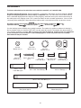
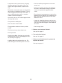
Before reading further, please review the drawing
below and familiarize yourself with the labeled parts.
BEFORE YOU BEGIN
Handrail
Upright
Accessory Tray
Key/Clip
Power Switch
Walking Belt
Adjustable
Platform Cushion
Foot Rail
Power Cord
Idler Roller
Adjustment Bolts
Console
Pulse Sensor
Book Holder

6
ASSEMBLY
T
o hire an authorized service technician to assemble the treadmill, call 1-800-445-2480.
Assembly requires two persons. Set the treadmill in a cleared area and remove all packing materials. Do not
dispose of the packing materials until assembly is completed. Note: The underside of the treadmill walking
b
elt is coated with high-performance lubricant. During shipping, some lubricant may be transferred to the top of
the walking belt or the shipping carton. This is normal and does not affect treadmill performance. If there is lubri-
cant on top of the walking belt, simply wipe off the lubricant with a soft cloth and a mild, non-abrasive cleaner.
Assembly requires the included hex keys and your own Phillips screwdriver ,
adjustable wrench , needlenose pliers , and scissors .
Use the drawings below to identify the assembly hardware. The number in parentheses below each drawing is
the key number of the part, from the PART LIST near the end of this manual. The number after the parentheses
is the quantity needed for assembly. Note: If a part is not in the hardware kit, check to see if it is preattached
to one of the parts to be assembled. To avoid damaging parts, do not use power tools for assembly.
Extra hardware may be included.
3/8" Star
Washer (11)–4
#8 x 1/2"
Screw (1)–12
#8 x 1" Tek Screw
(2)–4
3/8" Nut (10)–1
1/4" Star
Washer (12)–2
5/16" x 3/4"
Patch Bolt (5)–4
5/16" x 1 1/2"
Patch Bolt (4)–6
5/16" Star
Washer (9)–8
3/8" x 5 1/2" Patch Bolt (7)–4
1/4" x 1/2"
Patch Bolt (8)–6
Bolt Spacer (88)–4
Wheel Axle (97)–2
3/8" x 1 3/4" Patch Bolt (6)–1
3/8" x 2" Bolt (3)–1
1/4" x 5/8" Patch
Bolt (112)–4

7
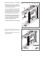
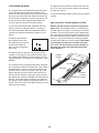
1. Make sure that the power cord is unplugged.
With the help of a second person, carefully tip
t
he treadmill onto its left side. Partially fold the
Frame (55) so that the treadmill is more stable;
d
o not fully fold the Frame yet.
Locate the Upright Wire (85), which is bundled
at the front of the Base (94). Remove the pack-
aging from the Upright Wire. Insert the Upright
Wire into the end of the Base and pull it out of
the indicated hole. If necessary, use the plastic
tie to pull the Upright Wire out of the hole.
Hold a Wheel (95) inside a Wheel Housing (96).
Press a Wheel Axle (97) through the Wheel.
Next, press the Wheel Housing into the Base
(94). Make sure that the tab on the Wheel
Housing is positioned as shown.
Attach the other Wheel (95) in the same way.
97
95
96
1
94
55
85
2. Attach four Base Feet (92) to the Base (94) in
the locations shown with four #8 x 1" Tek Screws
(2).
See the inset drawing. Cut the plastic tie near
the Upright Wire (85).
2
94
2
92
92
2
2
2
92
92
85
Hole
Tie
Cut
85
Tab
Tie
Tie
95

8
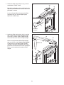
3. Identify the Right Upright Spacer (91), which is
marked with a “Right” sticker.
S
ee the inset drawing. Orient the Right Upright
Spacer (91) so that the two rounded corners are
p
ositioned as shown.
Insert the Upright Wire (85) through the Right
Upright Spacer (91). Set the Right Upright
Spacer on the Base (94).
85
91
3
91
Rounded
Corners
4. Identify the Right Upright (83), which is marked
with a “Right” sticker. Orient the Right Upright
Cover (86) as shown. Slide the Right Upright
Cover onto the lower end of the Right Upright.
Have a second person hold the Right Upright
(83) near the Base (94). See the inset drawing.
Tie the wire tie in the Right Upright securely
around the end of the Upright Wire (85). Then,
pull the other end of the wire tie until the Upright
Wire is routed completely through the Right
Upright.
94
Wire Tie
85
83
86
4
Wire
Tie
83
85
94
Rounded
Corners

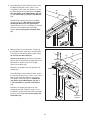
6. With the help of a second person, carefully tip
the treadmill onto its right side. Partially fold the
Frame (55) so that the treadmill is more stable;
do not fully fold the Frame yet.
See the inset drawing. Orient the Left Upright
Spacer (90) so that the two rounded corners are
positioned as shown. Set the Left Upright
Spacer on the Base (94).
Slide the Left Upright Cover (87) onto the Left
Upright (82).
Hold a Bolt Spacer (88) inside the lower end of
the Left Upright (82). Insert a 3/8" x 5 1/2" Patch
Bolt (7) with a 3/8" Star Washer (11) into the
Left Upright and the Bolt Spacer. Repeat this
step with a second Bolt Spacer (88), 3/8" x
5 1/2" Patch Bolt (7), and 3/8" Star Washer
(11).
Hold the Left Upright (82) against the Left
Upright Spacer (90). Tighten the 3/8" x 5 1/2"
Patch Bolts (7) until the heads of the Patch Bolts
touch the Left Upright; do not fully tighten the
Patch Bolts yet.
90
82
7
94
88
87
11
6
9
5. Hold a Bolt Spacer (88) inside the lower end of
the Right Upright (83). Insert a 3/8" x 5 1/2"
Patch Bolt (7) with a 3/8" Star Washer (11) into
the Right Upright and the Bolt Spacer. Repeat
t
his step with a second Bolt Spacer (88), 3/8"
x 5 1/2" Patch Bolt (7), and 3/8" Star Washer
(11).
H
old the Right Upright (83) against the Right
Upright Spacer (91). Be careful not to pinch
the Upright Wire (85) or the ground wire.
Tighten the 3/8" x 5 1/2" Patch Bolts (7) until the
heads of the Patch Bolts touch the Right
Upright; do not fully tighten the Patch Bolts
yet.
83
85
11
88
7
5
90
Rounded
Corners
Rounded
Corners
9
1
55

10
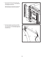
7. Attach the Base Cover (84) to the Base (94)
with four #8 x 1/2" Screws (1). Be careful not
to overtighten the Screws.
W
ith the help of a second person, tip the tread-
mill so that the Base (94) is flat on the floor.
84
94
1
1
7
8. Attach the Crossbar (113) to the Left Upright
(82) and the Right Upright (83) with four 1/4" x
5/8" Patch Bolts (112); do not fully tighten the
Patch Bolts yet.
82
83
113
112
112
8

11
10. With the help of a second person, hold the sides
of the console assembly and place the console
assembly near the Right Upright (83) and the
Left Upright (not shown). Do not lift the con-
sole assembly by the Right Handrail (79) or
the Left Handrail (not shown).
Connect the Upright Wire (85) to the console
wire. See the inset drawing. The connectors
should slide together easily and snap into
place. If they do not, turn one connector and try
again. IF YOU DO NOT CONNECT THE CON-
NECTORS PROPERLY, THE CONSOLE MAY
BECOME DAMAGED WHEN YOU TURN ON
THE POWER.
Remove the wire tie from the Upright Wire (85).
Console
Assembly
10
Console
Wire
Wire
Tie
85
79
83
85
Console
Wire
9. Set the console assembly face down on a soft
surface to avoid scratching the console.
I
dentify the Right Handrail (79). Hold the Right
Handrail near the console assembly. Route the
c
onsole wire through the large holes in the top
and bottom of the Right Handrail.
Set the Right Handrail (79) on the Console
Frame (81). Start a 1/4" x 1/2" Patch Bolt (8)
with a 1/4" Star Washer (12) into the Right
Handrail. Then, start two 5/16" x 1 1/2" Patch
Bolts (4) with two 5/16" Star Washers (9) into
the Right Handrail. Make sure that the console
wire is not pinched. Do not tighten the three
Patch Bolts yet.
Attach the Left Handrail (not shown) as de-
scribed above. Note: There is not a wire on
the left side.
79
Console
Assembly
4
8
12
9
81
C
onsole
Wire
9

12
12. Start two 1/4" x 1/2" Patch Bolts (8) into the
lower ends of both Handrails (78, 79). Tighten
all sixteen Patch Bolts (4, 5, 8).
Slide the Handrail Covers (77) against the
Uprights (82, 83).
See step 8. Tighten the four 1/4" x 5/8" Patch
Bolts (112).
12
79
82
77
83
78
8
8
8
77
4
5
4
Console
Assembly
11. Slide a Handrail Cover (77) onto the lower end
of each Handrail (78, 79).
Set the console assembly on the Left and Right
U
prights (82, 83). At the same time, insert the
lower end of the Handrails (78, 79) over the
brackets on the Uprights. Be careful not to
pinch any wires. Insert the excess wire into the
R
ight Upright.
Start four 5/16" x 3/4" Patch Bolts (5) with four
5/16" Star Washers (9) into the Uprights (82,
83). Then, start two 5/16" x 1 1/2" Patch Bolts
(4) into the Uprights. Do not tighten the Patch
Bolts yet.
11
79
4
77
77
82
4
78
C
onsole
Assembly
83
Bracket
Bracket
9
5
5
9
8
5

13
15. Make sure that all parts are properly tightened before you use the treadmill. If there are sheets of plastic
on the treadmill decals, remove the plastic. To protect the floor or carpet, place a mat under the treadmill.
Note: Extra hardware may be included. Keep the included hex keys in a secure place; one of the hex keys is
used to adjust the walking belt (see pages 26 and 27).
14. See page 16, and turn on the power. Next, see
step 4 on page 17, and lower the incline to the
lowest position. Then, remove the key from the
console, press the power switch to the off posi-
tion, and unplug the power cord.
Raise the Frame (55) to the position shown.
Have a second person hold the Frame until
this step is completed.
Orient the Storage Latch (51) so that the large
barrel and the latch knob are positioned as
shown.
Attach the upper end of the Storage Latch (51)
to the Frame (55) with a 3/8" x 1 3/4" Patch Bolt
(6).
Attach the lower end of the Storage Latch (51) to
the Base (94) with a 3/8" x 2" Bolt (3) and a 3/8"
Nut (10). Note: It may be necessary to move the
Frame (55) back and forth to align the Storage
Latch with the Base.
Lower the Frame (55) (see HOW TO LOWER
THE TREADMILL FOR USE on page 24).
51
94
10
Large
Barrel
Latch
Knob
3
6
55
14
13. See steps 5 and 6. Tighten the 3/8" x 5 1/2"
Patch Bolts (7).
See steps 4 and 6. Slide the Upright Covers
(
86, 87) down the Uprights (82, 83).
Attach the Left Accessory Tray (101) and the
Right Accessory Tray (104) to the console as-
s
embly with eight #8 x 1/2" Screws (1).
104
1
1
101
1
1
13
Console
A
ssembly

14
OPERATION AND ADJUSTMENT
T
HE PRE-LUBRICATED WALKING BELT
Your treadmill features a walking belt coated with high-
performance lubricant. IMPORTANT: Never apply sil-
i
cone spray or other substances to the walking
belt or the walking platform. Such substances will
cause excessive wear.
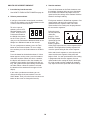
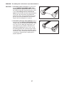
HOW TO PLUG IN THE POWER CORD
Your treadmill, like other electronic equipment, can be
damaged by sudden voltage changes in your homeʼs
power. To decrease the risk of damaging your
treadmill, always use a surge suppressor with your
treadmill (see drawing 1 at the right). To purchase
a surge suppressor, see precaution 12 on page 3.
Use only a single-outlet surge suppressor that is
UL 1449 listed as a transient voltage surge sup-
pressor (TVSS). The surge suppressor must have a
UL suppressed voltage rating of 400 volts or less
and a minimum surge dissipation of 450 joules.
The surge suppressor must be electrically rated for
120 volts AC and 15 amps. There must be a moni-
toring light on the surge suppressor to indicate
whether it is functioning properly. Failure to use a
properly functioning surge suppressor could dam-
age the control system of the treadmill (see precau-
tion 13 on page 3).
This product must be grounded. If it should malfunc-
tion or break down, grounding provides a path of least
resistance for electric current to reduce the risk of elec-
tric shock. This productʼs power cord has an equip-
ment-grounding conductor and a grounding plug. Plug
the power cord into a surge suppressor, and plug
the surge suppressor into an appropriate outlet
t
hat is properly installed and grounded in accor-
dance with all local codes and ordinances.
IMPORTANT: The treadmill is not compatible with
GFCI-equipped outlets.
This product is for use on a nominal 120-volt circuit
(see drawing 1). A temporary adapter may be used to
connect the surge suppressor to a 2-pole receptacle if
a properly grounded outlet is not available (see draw-
ing 2).
The temporary adapter should be used only until a
properly grounded outlet (see drawing 1) can be in-
stalled by a qualified electrician.
The green-colored rigid ear, lug, or the like extending
from the adapter must be connected to a permanent
ground such as a properly grounded outlet box cover.
The adapter must be held in place by a metal screw.
Some 2-pole receptacle outlet box covers are not
grounded. Contact a qualified electrician to deter-
mine if the outlet box cover is grounded before
using an adapter.
DANGER: Improper connection
of the equipment-grounding conductor in-
creases the risk of electric shock. Check with
a qualified electrician or serviceman if you
are unsure whether the product is properly
grounded. Do not modify the plug—if it will
not fit the outlet, have a proper outlet in-
stalled by a qualified electrician.
1
2
Grounded Outlet Box
Grounded Outlet Box
Grounding Plug
Surge Suppressor
Surge Suppressor
Grounding Pin
Adapter
Lug
Metal Screw
Grounded Outlet
Grounding Pin
Grounding Plug

15
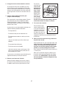
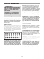
FEATURES OF THE CONSOLE
The treadmill console offers an impressive array of
features designed to make your workouts more effec-
tive and enjoyable. When you use the manual mode,
you can change the speed and incline with the touch of
a button. As you exercise, the console will display con-
tinuous exercise feedback. You can even measure
your heart rate using the handgrip pulse sensor.
In addition, the console features twenty-two preset
workouts—sixteen performance workouts and six
weight loss workouts. Each preset workout automati-
cally controls the speed and incline of the treadmill as
it guides you through an effective exercise session.
You can even compete against other runners using a
competition workout.
The console also features an iFit Live mode that en-
ables the treadmill to communicate with your wireless
network through an optional iFit Live module. With the
iFit Live mode, you can download personalized work-
outs, create your own workouts, track your workout re-
sults, and access many other features. To purchase
an iFit Live module at any time, go to www.iFit.com
or call the telephone number on the front cover of
this manual.
You can even listen to your favorite workout music or
audio books with the consoleʼs stereo sound system.
To turn on the power, see page 16. To use the man-
ual mode, see page 16. To use a preset workout,
see page 18. To use a competition workout, see
page 20. To use the stereo sound system, see page
22. To use the iFit Live mode, see page 22. To use
the information mode, see page 23.
IMPORTANT: If there is a sheet of plastic on the
console, remove the plastic. To prevent damage to
the walking platform, wear clean athletic shoes
while using the treadmill. The first time the tread-
mill is used, observe the alignment of the walking
belt, and center the walking belt if necessary (see
page 27).
CONSOLE
D
IAGRAM
Audio
J
ack

16
HOW TO TURN ON THE POWER
IMPORTANT: If the treadmill has been exposed to
c
old temperatures, allow it to warm to room tem-
perature before turning on the power. If you do not
d
o this, you may damage the console displays or
other electrical components.
Plug in the power cord (see
page 14). Next, locate the
power switch on the tread-
mill frame near the power
cord. Make sure that the
switch is in the reset
position.
IMPORTANT: The console features a display demo
mode, designed to be used if the treadmill is dis-
played in a store. If the displays light as soon as
you plug in the power cord and press the power
switch into the reset position, the demo mode is
turned on. To turn off the demo mode, hold down
the Stop button for a few seconds. If the displays
remain lit, see THE INFORMATION MODE on page
23 to turn off the demo mode.
Next, stand on the foot
rails of the treadmill.
Locate the clip at-
tached to the key, and
slide the clip securely
onto the waistband of
your clothes. Then, in-
sert the key into the
console. After a mo-
ment, the displays will light. IMPORTANT: In an emer-
gency, the key can be pulled from the console,
causing the walking belt to slow to a stop. Test the
clip by carefully taking a few steps backward; if the
key is not pulled from the console, adjust the posi-
tion of the clip.
Note: The console can display speed and distance in
either miles or kilometers. To find which unit of mea-
surement is selected, see THE INFORMATION MODE
on page 23. For simplicity, all instructions in this
manual refer to miles.
HOW TO USE THE MANUAL MODE
1. Insert the key into the console.
See HOW TO TURN ON THE POWER at the left.
2. Select the main menu.
Each time the key is in-
serted, the main menu
will appear. Note: If you
have selected a workout
or the iFit Live mode,
press the Menu button
on the screen to return
to the main menu.
3. Start the walking belt and adjust the speed.
To start the walking belt, press the Start button, the
Speed increase button, or one of the numbered
Quick Speed buttons. You can also press the Go
button on the screen.
If you press the Start button, the Speed increase
button, or the Go button, the walking belt will begin
to move at 1 mph. As you exercise, change the
speed of the walking belt as desired by pressing
the Speed increase and decrease buttons. Each
time you press one of the buttons, the speed set-
ting will change by 0.1 mph; if you hold down the
button, the speed setting will change in increments
of 0.5 mph.
If you press one of the numbered Quick Speed but-
tons, the walking belt will gradually change speed
until it reaches the selected speed setting. To se-
lect a speed setting that includes a decimal—such
as 3.5 mph—press two numbered buttons in suc-
cession. For example, to select a speed setting of
3.5 mph, press the 3 button and then immediately
press the 5 button.
To stop the walking belt, press the Stop button. To
restart the walking belt, press the Start button, the
Speed increase button, or one of the numbered
Quick Speed buttons.
Clip
Key
Reset

17
4. Change the incline of the treadmill as desired.
To change the incline of the treadmill, press the
I
ncline increase or decrease button or one of the
Quick Incline buttons numbered 0 to 12. Each time
y
ou press one of the buttons, the incline will gradu-
ally change until it reaches the selected incline set-
ting.
5. Select a display mode and monitor your
progress with the display.
The console offers several display modes. The dis-
play mode that you select will determine which
workout information is shown. To select the de-
sired display mode, repeatedly press the Display
button on the screen.
As you walk or run on the treadmill, the display can
show the following workout information:
• The elapsed time.
• The distance that you have walked or run.
• The approximate number of calories you have
burned.
• Your pace in minutes per mile or minutes per
kilometer.
• The speed of the walking belt.
• The incline level of the treadmill.
• Your heart rate (see step 6 on this page). Your
heart rate will be displayed only when you use
the handgrip pulse sensor.
As you exercise, the intensity meter will indicate the
approximate intensity level of your exercise.
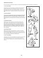
6. Measure your heart rate if desired.
Before using the handgrip pulse sensor, remove
the sheets of clear plastic from the metal contacts.
In addition, make sure that your hands are clean.
To measure
your heart rate,
stand on the
f
oot rails and
hold the con-
t
acts—avoid
moving your
hands. When
your pulse is
detected, your
heart rate will
be shown. For
the most accurate heart rate reading, continue
to hold the contacts for about 15 seconds.
7. Turn on the fan if desired.
The fan features high
and low speed settings.
Press the Fan button re-
peatedly to select a fan
speed or to turn off the
fan. Note: If the fan is on
when the walking belt is
stopped, the fan will turn off automatically after a
few minutes.
8. When you are finished exercising, remove the
key from the console.
Step onto the foot rails, press the Stop button, and
adjust the incline of the treadmill to the lowest
setting. The incline must be at the lowest set-
ting when you fold the treadmill to the storage
position, or you may damage the treadmill.
Next, remove the key from the console and put it in
a secure place.
When you are finished using the treadmill, press
the power switch into the off position and unplug
the power cord. IMPORTANT: If you do not do
this, the treadmillʼs electrical components may
wear prematurely.
Contacts

18
HOW TO USE A PRESET WORKOUT
1. Insert the key into the console.
See HOW TO TURN ON THE POWER on page 16.
2. Select a preset workout.
If you have selected the manual mode, a workout,
or the iFit Live mode, press the Menu button on the
screen to return to the main menu.
To select a preset
workout, press the iFit
Workouts button on the
screen. Then press the
Performance button or
the Weight Loss button
on the screen. You can
also press the Performance Workouts button or the
Weight Loss Workouts button on the console.
To use a performance workout, press the Time
button or the Distance button. To use a weight
loss workout, press the Calorie button or the Basic
button.
Press the button for the desired workout. If a Next
button appears on the screen, press the button to
view more workouts. When you select a workout,
the display will show the name, the duration, the
maximum speed setting, the maximum incline set-
ting, and a profile of the speed settings of the work-
out. Note: When a distance workout is selected,
the duration of the workout will not appear in the
display.
If you select a performance workout, you can
change the intensity of your workout. Press the
Select button. Then, press the increase or decrease
button on the screen to change the intensity.
3. Start the workout.
Press the Start button or the Select button to start
t
he workout. A moment after you press the button,
the treadmill will automatically adjust to the first
s
peed and incline settings of the workout. Hold the
handrails and begin walking.
Each preset workout is divided into segments. One
speed setting and one incline setting are pro-
grammed for each segment. Note: The same
speed and/or incline setting may be programmed
for consecutive segments.
During the work-
out, the profile will
show your
progress. Press
the Display button
repeatedly to view
the profile. The
flashing segment
of the profile represents the current segment of the
workout. The height of the flashing segment indi-
cates the speed setting for the current segment.
At the end of each segment, a series of tones will
sound and the next segment of the profile will
begin to flash. If a new speed and/or incline setting
is programmed for the next segment, the new
speed and/or incline setting will flash in the display
for a few seconds and the treadmill will automati-
cally adjust to the new speed and incline settings.

19
The workout will continue in this way until the last
segment of the profile flashes and the last seg-
ment ends. The walking belt will then slow to a
s
top. Some workouts will be followed by a cool
down period.
Note: The calorie goal for each weight loss
workout is an estimate of the number of calo-
ries that you will burn during the workout. The
actual number of calories that you burn will de-
pend on your weight. In addition, if you manu-
ally change the speed or incline of the treadmill
during the workout, the number of calories you
burn will be affected.
If the speed or incline setting is too high or too low
at any time during the workout, you can manually
override the setting by pressing the Speed or
Incline buttons; however, when the next segment
of the workout begins, the treadmill will auto-
matically adjust to the speed and incline set-
tings for the next segment.
To stop the workout at any time, press the Stop
button. To restart the workout, press the Start but-
ton or the Speed increase button. The walking belt
will begin to move at 1 mph. When the next seg-
ment of the workout begins, the treadmill will auto-
matically adjust to the speed and incline settings
for the next segment.
4. Select a display mode and monitor your
progress with the display.
S
ee step 5 on page 17.
I
f you select a time workout, the display can show
a stopwatch representing the time remaining in the
workout. If you select a distance workout, the dis-
play can show a track representing 1/4 mile (400
meters). If you select a calorie workout, the display
can show a flame representing 25 calories.
5. Measure your heart rate if desired.
See step 6 on page 17.
6. Turn on the fan if desired.
See step 7 on page 17.
7. When you are finished exercising, remove the
key from the console.
See step 8 on page 17.

20
HOW TO USE A COMPETITION WORKOUT
1. Insert the key into the console.
See HOW TO TURN ON THE POWER on page 16.
2. Select a competition workout.
If you have selected the manual mode, a workout,
or the iFit Live mode, press the Menu button to re-
turn to the main menu.
To select a competition
workout, press the iFit
Workouts button on the
screen. Then press the
Competition button on
the screen. You can
also press the
Competition Workouts button on the console.
To personalize race settings, press the Settings
button. Select a maximum incline by pressing the
increase and decrease buttons. Press the
Continue button. Then, select the speed at which
you will start walking in the race by pressing the in-
crease and decrease buttons. Press the Continue
button.
You can race against one opponent or against a
group of four opponents.
If you choose to compete against one opponent,
press the Head to Head button. Select an opponent
by pressing the Next and Back buttons. For each
the opponent, the screen will display the oppo-
nentʼs level of endurance, average speed, maxi-
mum speed, and level of spirit. Each opponent may
appear more than once in different levels, or tiers,
of difficulty. The least challenging opponent is in
tier one and the most challenging opponent is in
tier three. Press the Select button.
If you choose to compete against a group, press
the Race Against a Pack button. Select a level of
difficulty for the race by pressing the increase and
d
ecrease buttons. Level one is the easiest level
and level twelve is the hardest. Press the Continue
b
utton.
Then, select the distance of the race. You can view
more distances by pressing the Next button on the
screen.
3. Start the workout.
After you select a distance, READY, SET, GO will
appear on the screen and then the race will begin.
Hold the handrails and begin walking.
Adjust the speed and incline of the treadmill as de-
sired. Your opponents will adjust their speed and
tactics based on the course and the situation.
The workout will continue until you complete the
race.
4. Select a display mode and monitor your
progress with the display.
The console offers several display options. The dis-
play option you select will determine which workout
information is shown. Press the Display button re-
peatedly to select the desired display option.
As you walk or run on the treadmill, the screen can
show the following workout information:
• An animation of a runner labeled “U,” which rep-
resents you. As you increase or decrease the
speed of the walking belt, the runner will speed
up or slow down.
• Animations of the other runners.
Page is loading ...
Page is loading ...
Page is loading ...
Page is loading ...
Page is loading ...
Page is loading ...
Page is loading ...
Page is loading ...
Page is loading ...
Page is loading ...
Page is loading ...
Page is loading ...
Page is loading ...
Page is loading ...
Page is loading ...
Page is loading ...
-
 1
1
-
 2
2
-
 3
3
-
 4
4
-
 5
5
-
 6
6
-
 7
7
-
 8
8
-
 9
9
-
 10
10
-
 11
11
-
 12
12
-
 13
13
-
 14
14
-
 15
15
-
 16
16
-
 17
17
-
 18
18
-
 19
19
-
 20
20
-
 21
21
-
 22
22
-
 23
23
-
 24
24
-
 25
25
-
 26
26
-
 27
27
-
 28
28
-
 29
29
-
 30
30
-
 31
31
-
 32
32
-
 33
33
-
 34
34
-
 35
35
-
 36
36


Ask a question and I''ll find the answer in the document
Finding information in a document is now easier with AI
Related papers
-
ProForm 400 ZLT PETL49910.0 User manual
-
Pro-Form PFTL39511.0 User manual
-
-
-
-
-
NordicTrack Power 995 User manual
-
ProForm Power 690 User manual
-
-
Other documents
-
-
-
-
HealthRider Treadmill H90T User manual
-
-
-
-
-
FreeMotion 30441.0 User manual
-
Weslo CADENCE 26.0 User manual