Page is loading ...

MANUAL
CHAIN HOIST
CB SERIES
MODEL M3
1/2 Ton through 20 Ton Capacity
Code, Lot and Serial Number
EFFECTIVE: February 3, 2011
This equipment should not be installed, operated or
maintained by any person who has not read and understood
all the contents of this manual. Failure to read and comply
with the contents of this manual can result in serious bodily
injury or death, and/or property damage.

2
Table of Contents
1.0 Important Information and Warnings ……………………………………………………………………… 4
Section Page Number
1.1 Terms and Summary
1.2 Warning Tags and Labels
2.0 Technical Information…………………………………………………………………………….…………. 7
2.1 Specifications
2.2 Dimensions
2.3 Optional Equipment
3.0 Preoperational Procedures ……………………………………………………………………………… 11
3.1 Chain
3.2 Attachment Points
3.3 Mounting the Hoist
3.4 Preoperational Checks and Trial Operation
4.0 Operation …………………………………………………………………………………………………... 13
4.1 Introduction
4.2 Shall’s and Shall Not’s for Operation
4.3 Operation
4.4 Principal and Operation of the Slip Clutch
5.0 Inspection ………………………………………………………………………………………………….. 16
5.1 General
5.2 Inspection Classification
5.3 Frequent Inspection
5.4 Periodic Inspection
5.5 Occasionally Used Hoists
5.6 Inspection Records
5.7 Inspection Methods and Criteria

3
6.0 Maintenance & Handling …………………………………………………………………………………. 26
Section Page Number
6.1 Lubrication
6.2 Disassembly, Assembly and Adjustment
6.3 Hoist Disassembly
6.4 Hoist Assembly
6.5 Storage
6.6 Outdoor Installation
7.0 Troubleshooting …………………………………………………………………………………………… 36
8.0 Warranty …………………………………………………………………………………………………… 39
9.0 Parts List …………………………………………………………………………………………………… 41

4
1.0 Important Information and Warnings
1.1 Terms and Summary
This manual provides important information for personnel involved with the installation, operation and
maintenance of this product. Although you may be familiar with this or similar equipment, it is strongly
recommended that you read this manual before installing, operating, or maintaining the product.
Danger, Warning, Caution, and Notice
Throughout this manual there are steps and procedures that can present hazardous situations. The following
signal words are used to identify the degree or level of hazard seriousness.
Danger indicates an imminently hazardous situation which, if not avoided, will result in
death or serious injury, and property damage.
Warning indicates an imminently hazardous situation which, if not avoided, could result in
death or serious injury, and property damage.
Caution indicates a potentially hazardous situation which, if not avoided, may result in
minor or moderate injury or property damage.
Notice is used to notify people of installation, operation, or maintenance information which
is important but not directly hazard-related.
These general instructions deal with the normal installation, operation, and maintenance situations encountered with
the equipment described herein. The instructions should not be interpreted to anticipate every possible contingency
or to anticipate the final system, crane, or configuration that uses this equipment. For systems using the equipment
covered by this manual, the supplier and owner of the system are responsible for the system’s compliance with all
applicable industry standards, and with all applicable federal, state, and local regulations/codes.
This manual includes instructions and parts information for a variety of hoist types. Therefore, all instructions and
parts information may not apply to any one type or size of specific hoist. Disregard those portions of the instructions
that do not apply.
Record your hoist’s Code, Lot and Serial Number (see Section 9) on the front cover of this manual for identification
and future reference to avoid referring to the wrong manual for information or instructions on installation, operation,
inspection, maintenance, or parts.
Use only Harrington authorized replacement parts in the service and maintenance of this hoist.

5
Equipment described herein is not designed for and
MUST NOT
be used for lifting, supporting, or transporting
people, or for lifting or supporting loads over people.
Equipment described herein should not be used in conjunction with other equipment unless necessary and/or
required safety devices applicable to the system, crane, or application are installed by the system designer, system
manufacturer, crane manufacturer, installer, or user.
Modifications to upgrade, rerate, or otherwise alter this equipment shall be authorized only by the original equipment
manufacturer.
If a below-the-hook lifting device or sling is used with a hoist, refer to ANSI/ASME B30.9, “Safety Standard for
Slings” or ANSI/ASME B30.20, “Safety Standard for Below-the-Hook Lifting Devices”.
Hoists used to handle hot molten material may require additional equipment or devices. Refer to ANSI Z241.2,
“Safety Requirements for Melting and Pouring of Metals in the Metalcasting Industry”.
Failure to read and comply with any one of the limitations noted herein can result in serious bodily injury or death,
and/or property damage.
It is the responsibility of the owner/user to install, inspect, test, maintain, and operate a hoist in accordance with
ANSI/ASME B30.16, “Overhead Hoists (Underhung)” and OSHA Regulations. If the hoist is installed as part of a
total lifting system, such as an overhead crane or monorail, it is also the responsibility of the owner/user to comply
with the applicable ANSI/ASME B30 volume that addresses that type of equipment.
It is the responsibility of the owner/user to have all personnel that will install, inspect, test, maintain, and operate a
hoist read the contents of this manual and applicable portions of ANSI/ASME B30.16, “Overhead Hoists
(Underhung)” and OSHA Regulations.
If the hoist owner/user requires additional information, or if any information in the manual is not clear, contact
Harrington or the distributor of the hoist. Do not install, inspect, test, maintain, or operate this hoist unless this
information is fully understood.
A regular schedule of inspection of the hoist in accordance with the requirements of ANSI/ASME B30.16 should be
established and records maintained.

6
1.2 Warning Tags and Labels
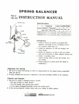
The warning tag illustrated below in Figure 1-1 is supplied with each hoist shipped from the factory. If the tag is
not attached to your hoist’s no-load side of the load chain, order a tag from your dealer and install it. Read and
obey all warnings attached to this hoist. Tag is not shown actual size.
Front Back
Figure 1-1 Warning Tag Attached to Hoist (shown larger for legibility)

7
2.0 Technical Information
2.1 Specifications
2.1.1 Product Code
2.1.2 Operating Conditions and Environment
Temperature range: -4° to +140°F (-20° to +60°C)
Humidity: 100% or less (Not an Underwater Device)
Table 2-1 Hoist Specifications
Cap.
(Tons)
Product
Code
Std.
Lift
(ft)
Pull to
Lift
Load
(lbs)
Load Chain
Diameter
(mm) x
Chain Fall
Lines
Overhaul
Ratio
Net
Weight
(lbs)
Shipping
Weight
Approx.
(lbs)
Weight for
Additional
One Foot
of Lift (lbs)
½ CB005
8
48 5.0x1 25 22 23 1.0
1 CB010 58 6.3x1 43 25 26 1.2
1½ CB015 70 7.1x1 57 32 33 1.4
2 CB020 72 8.0x1 70 41 43 1.6
2 ½ CB025 66 9.0x1 99 56 58 1.8
3 CB030 72 7.1x2 114 49 53 2.1
5 CB050 68 9.0x2 198 85 89 3.0
8 CB080 75 9.0x3 297 124 131 4.2
10 CB100
12
72 9.0x4 396 186 203 5.5
15 CB150 74 9.0x6 594 346 368 7.9
20 CB200 72x2 9.0x8 396x2 524 678 10.9
*NOTE: Any lift of chain is available on request. Simply specify the length of chain desired when ordering.
Because Harrington chains are specially heat treated, only authentic Harrington chains should be used on your
hoist. NEVER attempt to lengthen the chain by attaching additional chain links to it or by any other means.

8
2.2 Dimensions
Table 2-2 Hoist Dimensions
Cap.
(Tons)
Product
Code
Headroom
c
(in)
a
(in)
b
(in)
d
(ft)
e
(in)
f
(in)
g
(in)
x
(in)
1/2 CB005 11.2 6.2 6.3 8.0 2.7 3.9 1.1 3.5
1 CB010 11.6 6.4 6.3 8.0 2.8 3.9 1.1 4.0
1 1/2 CB015 13.8 6.7 7.2 8.0 3.1 4.4 1.3 4.7
2 CB020 14.8 7.2 8.0 8.0 3.4 4.9 1.4 4.9
2 1/2 CB025 16.5 7.6 9.2 8.0 3.6 5.6 1.6 5.4
3 CB030 20.1 6.7 9.3 8.3 3.1 6.4 1.7 5.8
5 CB050 23.6 7.6 11.1 10.0 3.6 7.6 1.8 6.8
8 CB080 30.3 7.6 14.7 10.3 3.6 10.0 2.9 10.8
10 CB100 29.9 7.6 17.2 14.9 4.4 12.1 2.9 11.6
15 CB150 40.2 10.6 19.4 15.9 4.7 13.3 3.1 12.6
20 CB200 46.5 14.7 29.4 16.3 7.4 14.7 3.2 13.8
CB005 to CB025
CB030 to CB050
CB080
Figure 2-1
Figure 2-2
Figure 2-3
CB100 to CB150
CB200
Figure 2-4
Figure 2-5

9
Table 2-3 Hook Dimension*
T = Top Hook
B = Bottom Hook
Units = inch
Cap.
(Tons)
Product
Code
Hook a b c d e g
1/2 CB005
T & B
0.8 0.5 0.7 0.5 1.4 1.1
1 CB010 1.0 0.6 0.9 0.6 1.7 1.1
1½ CB015 1.2 0.8 1.0 0.8 1.9 1.3
2 CB020 1.4 0.9 1.2 0.9 2.0 1.4
2 ½ CB025 1.6 1.0 1.3 1.0 2.1 1.6
3 CB030 1.8 1.1 1.5 1.1 2.2 1.7
5 CB050 2.2 1.4 1.9 1.4 2.5 1.8
8 CB080 3.0 1.9 2.5 1.9 3.3 2.9
10 CB100 3.0 1.9 2.5 1.9 3.3 2.9
15 CB150 3.7 2.4 3.1 2.4 3.9 3.1
20 CB200 4.2 2.6 3.5 2.6 4.3 3.2
*Refer to Section 5.7 for inspection dimensions and limits.
2.3 Optional Equipment
2.3.1 Optional Latch Lock Hooks
The Bullard hook has a conventional hook shape with a special, heavy-duty, rotating, spring-
loaded, locking latch. The latch remains locked until it is released by the operator. Refer to Figure
2-6.
The Shur-Loc hook is a special design hook where the latch remains fixed and the hook swings
to unlock. The hook cannot be opened while a load is applied.
Installation of these hooks may change the headroom.
See Section 9.4, Parts List for a complete Latch Lock Hook part listing.
Figure 2-6 Latch Lock Hooks

10
2.3.2 Optional Inspection Hooks
The Inspection Hook is designed to facilitate the inspection of the internal surfaces of the hook
yoke and shank portion of the hook itself. The Inspection Hook is suitable for applications where
inspection of the internal parts of the hook set is required. The inspection hook uses the standard
Harrington hook set and is assembled with high-strength locking fasteners instead of rivets.
Inspection hooks are available in top and bottom versions. Refer to Figure 2-7.
Disassembly and re-assembly involves removal and reinstallation of the yoke fasteners of the
Inspection Hook Set Assembly followed by testing of the hoist prior to returning it to service.
The Inspection Hook is available for CB005 through CB025 hoists.
See Section 9.4, Parts List for a complete Inspection Hook part listing.
Figure 2-7 Inspection Hooks
2.3.3 Optional Chain Containers
Chain containers are sized based on the capacity and lift of the hoist. The containers are
constructed from vinyl coated canvas with a steel frame on top. The containers are prepared
differently depending on the host model. See Harrington document EDOC0154 for sizing
information.
Figure 2-8 CB Chain Container

11
3.0 Preoperational Procedures
3.1 Chain
3.1.1
Verify that the load chain is not twisted or tangled prior to operating the hoist.
Make sure the bottom hook on the 3 (CB030) through the 20 (CB200) Ton multiple fall hoists is not
capsized. See Figures 3-1 and 3-2. Correct all chain irregularities before conducting the first hoist
operation.
Figure 3-1 Twist in Load Chain – Double Fall Model
Figure 3-2 Capsized Hook and Chain – Double Fall Model

12
3.2 Attachment Points
3.2.1
Prior to attaching the hoist ensure that all attachment points, suspension
components and supporting structure are adequate to support the hoist and its load. If necessary
consult a professional that is qualified to evaluate the adequacy of the suspension location and its
supporting structure.
3.2.2
See Section 6.6 for outdoor installation considerations.
3.3 Mounting the Hoist
3.3.1 Hook Mounted to a Fixed Location - Attach the hoist’s top hook to the fixed suspension point.
3.3.2
Ensure that the fixed suspension point rests on the center of the hook’s saddle and
that the hook’s latch is engaged.
3.4 Preoperational Checks and Trial Operation
3.4.1
Confirm the adequacy of the rated capacity for all slings, chains, wire ropes and all
other lifting attachments before use. Inspect all load suspension members for damage prior to use and
replace or repair all damaged parts.
3.4.2
Verify and correct all chain irregularities prior to operating the hoist. Refer to
Section 3.1.
3.4.3 Measure and record the “k” dimension of all hooks on hoist. See Table 5-4 under Section 5,
“Inspection”.
3.4.4 Record the hoist's Code, Lot and Serial Number (from the name plate on the hoist; see Section 9) in
the space provided on the cover of this manual.
3.4.5 Ensure that the hoist is properly installed to a fixed point.
3.4.6 Ensure that all nuts, bolts and split pins (cotter pins) are sufficiently fastened.
3.4.7 Confirm proper operation.
Before operating read and become familiar with Section 4 - Operation.
Before operating ensure that the hoist meets the Inspection, Testing and Maintenance
requirements of ANSI/ASME B30.16.
Before operating ensure that nothing will interfere with the full range of the hoist’s operation.

13
4.0 Operation
4.1 Introduction
DO
NOT
WALK UNDER A SUSPENDED LOAD
HOIST OPERATORS SHALL BE REQUIRED TO READ THE OPERATION SECTION OF THIS MANUAL, THE
WARNINGS CONTAINED IN THIS MANUAL, INSTRUCTION AND WARNING LABELS ON THE HOIST OR
LIFTING SYSTEM, AND THE OPERATION SECTIONS OF ANSI/ASME B30.16 and ANSI/ASME B30.10. THE
OPERATOR SHALL ALSO BE REQUIRED TO BE FAMILIAR WITH THE HOIST AND HOIST CONTROLS
BEFORE BEING AUTHORIZED TO OPERATE THE HOIST OR LIFTING SYSTEM.
HOIST OPERATORS SHOULD BE TRAINED IN PROPER RIGGING PROCEDURES FOR THE ATTACHMENT
OF LOADS TO THE HOIST HOOK.
HOIST OPERATORS SHOULD BE TRAINED TO BE AWARE OF POTENTIAL MALFUNCTIONS OF THE
EQUIPMENT THAT REQUIRE ADJUSTMENT OR REPAIR, AND TO BE INSTRUCTED TO STOP OPERATION
IF SUCH MALFUNCTIONS OCCUR, AND TO IMMEDIATELY ADVISE THEIR SUPERVISOR SO CORRECTIVE
ACTION CAN BE TAKEN.
HOIST OPERATORS SHOULD HAVE NORMAL DEPTH PERCEPTION, FIELD OF VISION, REACTION TIME,
MANUAL DEXTERITY, AND COORDINATION.
HOIST OPERATORS SHOULD
NOT
HAVE A HISTORY OF OR BE PRONE T
O SEIZURES, LOSS OF
PHYSICAL CONTROL, PHYSICAL DEFECTS, OR EMOTIONAL INSTABILITY THAT COULD RESULT IN
ACTIONS OF THE OPERATOR BEING A HAZARD TO THE OPERATOR OR TO OTHERS.
HOIST OPERATORS SHOULD NOT
OPERATE A HOIST OR LIFTING SYSTEM WHEN UNDER THE
INFLUENCE OF ALCOHOL, DRUGS, OR MEDICATION.
• Read ANSI/ASME B30.16 and ANSI/ASME B30.10.
• Read the hoist manufacturer’s Operating and Maintenance Instructions.
• Read all labels attached to equipment.
The operation of a hoist involves more than activating the hoist’s controls. Per the ANSI/ASME B30 standards, the use
of a hoist is subject to certain hazards that cannot be mitigated by engineered features, but only by the exercise of
intelligence, care, common sense, and experience in anticipating the effects and results of activating the hoist’s controls.
Use this guidance in conjunction with other warnings, cautions, and notices in this manual to govern the operation and
use of your hoist.

14
4.2 Shall’s and Shall Not’s for Operation
Improper operation of a hoist can create a potentially hazardous
situation which, if not avoided, could result in
death or serious injury
,
and substantial property damage. To avoid such a potentially
hazardous situation THE OPERATOR SHALL:
•
NOT
•
lift more than rated load for the hoist.
NOT
•
use damaged hoist or hoist that is not working
properly.
NOT
•
use hoist with twisted, kinked, damaged, or
worn chain.
NOT
•
use hoist if the bottom hook is capsized
(multiple fall hoists - see Section 3.1).
NOT
•
use the hoist to lift, support, or transport
people.
NOT
•
lift loads over people.
NOT
•
apply load unless load chain is properly
seated in the load sheave (and idle sheave for hoist
with multiple chain falls).
NOT
•
use the hoist in such a way that could result in
shock or impact loads being applied to the hoist.
NOT
•
attempt to lengthen the load chain or repair
damaged load chain.
NOT
•
operate hoist when it is restricted from forming
a straight line from hook to hook in the direction of
loading.
NOT
•
use load chain as a sling or wrap load chain
around load.
NOT
•
apply load if binding prevents equal loading
on all load-supporting chains.
NOT
•
operate beyond the limits of the load chain
travel.
NOT
•
support load on hook tip unless hook is
designed for tip loading.
NOT
use in a way that causes either hook to be
side-loaded.
•
NOT
•
leave load supported by the hoist unattended
unless specific precautions have been taken.
NOT
•
allow the chain, or hook to be used as an
electrical or welding ground.
NOT
•
allow the chain, or hook to be touched by a
live welding electrode.
NOT
•
remove or obscure the warnings on the hoist.
NOT
• Be familiar with operating controls, procedures, and
warnings.
operate a hoist on which the safety placards
or decals are missing or illegible.
• Make sure the unit is securely attached to a
suitable support before applying load.
• Make sure load slings or other approved single
attachments are properly sized, rigged, and seated
in the hook saddle.
• Take up slack carefully - make sure load is
balanced and load-holding action is secure before
continuing.
• Make sure all persons stay clear of the supported
load.
• Protect the hoist’s load chain from weld splatter or
other damaging contaminants.
• Report Malfunctions or unusual performances
(including unusual noises) of the hoist and remove
the hoist from service until the malfunction or
unusual performance is resolved.
• Warn personnel before lifting or moving a load.
• Warn personnel of an approaching load.

15
Improper operation of a hoist can create a potentially hazardous
situation which, if not avoided, could result in
minor or moderate
injury
• Maintain a firm footing or be otherwise secured
when operating the hoist.
• Check brake function by tensioning the hoist prior
to each lift operation.
• Use hook latches. Latches are to retain slings,
chains, etc. under slack conditions only.
• Make sure the hook latches are closed and not
supporting any parts of the load.
• Make sure the load is free to move and will clear all
obstructions.
• Avoid swinging the load or hook.
• Make sure hook travel is in the same direction as
shown on controls.
, or property damage. To avoid such a potentially hazardous
situation THE OPERATOR SHALL:
• Inspect the hoist regularly, replace damaged or
worn parts, and keep appropriate records of
maintenance.
• Use the hoist manufacturer’s recommended parts
when repairing the unit.
• Lubricate load chain per hoist manufacturer’s
recommendations.
•
NOT
•
use the hoist load limiting or warning device to
measure load.
NOT
•
allow your attention to be diverted from
operating the hoist.
NOT
•
allow the hoist to be subjected to sharp
contact with other hoists, structures, or objects
through misuse.
NOT
perform such adjustments or repair.
adjust or repair the hoist unless qualified to
4.3 Operation
1) Face the hand chain wheel side of the hoist.
2) To raise the load, pull hand chain clockwise.
3) To lower the load, pull hand chain counterclockwise.
NOTE: The clicking sound of the pawl when a load is being raised indicates normal operation.
4.4 Principle and Operation of the Slip Clutch
: IMPROPER chain hoist use could result in death or serious injury. To avoid these hazards:
: NEVER disassemble or attempt to adjust the slip clutch assemby. Any attempt to do so will void
the warranty. Contact your closest Harrington Distributor if service is required.
The standard slip clutch device prevents the hoist from being used to lift damaging loads beyond the rated capacity of
the manual chain hoist. When an applied load exceeds the preset value, the hand chain wheel rotates idly. The
mechanism is a friction clutch system located between the hand chain wheel and the mechanical brake.

16
5.0 Inspection
5.1 General
5.1.1 The inspection procedure herein is based on ANSI/ASME B30.16. The following definitions are from
ANSI/ASME B30.16 and pertain to the inspection procedure below.
Designated Person
– a person selected or assigned as being competent to perform the specific
duties to which he/she is assigned.
Qualified Person
– a person who, by possession of a recognized degree or certificate of
professional standing, or who, by extensive knowledge, training, and experience, has successfully
demonstrated the ability to solve or resolve problems relating to the subject matter and work.
Normal Service
– that distributed service which involves operation with randomly distributed loads
within the rated load limit, or uniform loads less than 65% of rated load for not more than 15% of
the time.
Heavy Service
– that service which involves operation within the rated load limit which exceeds
normal service.
Severe Service
5.2 Inspection Classification
– that service which involves normal or heavy service with abnormal operating
conditions.
5.2.1 Initial Inspection – prior to initial use, all new, altered, or modified hoists shall be inspected by a
designated person to ensure compliance with the applicable provisions of this manual.
5.2.2 Inspection Classification – the inspection procedure for hoists in regular service is divided into two
general classifications based upon the intervals at which inspection should be performed. The intervals
in turn are dependent upon the nature of the critical components of the hoist and the degree of their
exposure to wear, deterioration, or malfunction. The two general classifications are herein designated
as FREQUENT and PERIODIC, with respective intervals between inspections as defined below.
5.2.3 FREQUENT Inspection – visual examinations by the operator or other designated personnel with
intervals per the following criteria:
Normal service – monthly
Heavy service – weekly to monthly
Severe service – daily to weekly
Special or infrequent service – as recommended by a qualified person before and after each
occurrence.
5.2.4 PERIODIC Inspection – visual inspection by a designated person with intervals per the following
criteria:
Normal service – yearly
Heavy service – semiannually
Severe service – quarterly
Special or infrequent service – as recommended by a qualified person before the first such
occurrence and as directed by the qualified person for any subsequent occurrences.

17
5.3 Frequent Inspection
5.3.1 Inspections should be made on a FREQUENT basis in accordance with Table 5-1, “Frequent
Inspection.” Included in these FREQUENT Inspections are observations made during operation for
any defects or damage that might appear between Periodic Inspections. Evaluation and resolution of
the results of FREQUENT Inspections shall be made by a designated person such that the hoist is
maintained in safe working condition.
Table 5-1 Frequent Inspection
All functional operating mechanisms for proper operation and adjustment, maladjustment and
unusual sounds.
Hoist braking system for proper operation
Hooks and latches in accordance with ANSI/ASME B30.10
Hook latch operation
Load chain in accordance with Section 5.7
Load chain reeving for compliance with Section 3.1 and 6.4
Hoist support for damage
5.4 Periodic Inspection
5.4.1 Inspections should be made on a PERIODIC basis in accordance with Table 5-2, “Periodic Inspection.”
Evaluation and resolution of the results of PERIODIC Inspections shall be made by a designated
person such that the hoist is maintained in safe working condition.
5.4.2 For inspections where load suspension parts of the hoist are disassembled, a load test per ANSI/ASME
B30.16 must be performed on the hoist after it is re-assembled and prior to its return to service.
Table 5-2 Periodic Inspection
Requirements of frequent inspection.
Evidence of loose bolts, nuts, or rivets.
Evidence of worn, corroded, cracked, or distorted parts such as load blocks, suspension housing,
chain attachments, clevises, yokes, suspension bolts, shafts, gears, bearings, pins, rollers and
locking and clamping devices.
Evidence of damage to hook retaining nuts or collars and pins, and welds or rivets used to secure
the retaining members.
Evidence of damage or excessive wear of load and idler sheaves.
Evidence of worn, glazed or oil contaminated friction disks; worn pawls, cams or ratchet; corroded,
stretched, or broken pawl springs in brake mechanism.
Evidence of damage to supporting structure.
Function label on hoist for legibility.
Warning label properly attached to the hoist and legible (see Section 1.2).
End connection of load chain.

18
5.5 Occasionally Used Hoists
5.5.1 Hoists that are used infrequently shall be inspected as follows prior to placing in service:
Hoist Idle More Than 1 Month, Less Than 1 Year
: Inspect per FREQUENT Inspection criteria in
Section 5.3.
Hoist Idle More Than 1 Year
5.6 Inspection Records
: Inspect per PERIODIC Inspection criteria in Section 5.4.
5.6.1 Dated inspection reports and records should be maintained at time intervals corresponding to those
that apply for the hoist’s PERIODIC interval per Section 5.2.4. These records should be stored where
they are available to personnel involved with the inspection, maintenance, or operation of the hoist.
5.6.2 A long range chain inspection program should be established and should include records of
examination of chains removed from service so a relationship can be established between visual
observation and actual condition of the chain.
5.7 Inspection Methods and Criteria
5.7.1 This section covers the inspection of specific items. The list of items in this section is based on those
listed in ANSI/ASME B30.16 for the Frequent and Periodic Inspection.
5.7.2 Frequent Inspection - Not intended to involve disassembly of the hoist. Disassembly for further
inspection would be required only if frequent inspection results so indicate. Disassembly and further
inspection should only be performed by a qualified person trained in the disassembly and re-assembly
of the hoist.
5.7.3 Periodic Inspection - Disassembly of the hoist is required. Disassambly should only be performed by a
qualified person trained in the disassembly and re-assembly of the hoist.
Table 5-3 Hoist Inspection Methods and Criteria
Item Method Discard Limit/Criteria Action
Functional operating
mechanisms.
Visual, Auditory Mechanisms should be properly adjusted and
should not produce unusual sounds when operated.
Components should not be deformed, scarred, or
show significant wear. Refer to Figures 5-2, 5-3 and
5-4.
Repair or replace
as required.
Hooks – Stretch Measure The "k" dimension should not be greater than 1.05
times that measured and recorded at the time of
purchase (See Section 3.4). If recorded "k" values
are not available for hooks when new, use nominal
"k" values from Table 5-4.
Replace.
Hooks – Fretting
wear
Measure The "u" and "t" dimensions should not be less than
discard value listed in Table 5-4.
Replace.
Hooks – Surface
Condition
Visual Should be free of gouges, deep nicks, dents, weld
splatter, and significant corrosion.
Replace.
Hooks –
Deformation
Visual Should be free of twists and deformations. See
Figure 5-1.
Replace.
Hooks – Bent Shank
or Neck
Visual Shank and neck portions of hook should be free of
deformations.
Replace.
Hooks – Swivel Visual, Function Bearing parts and surfaces should not show
significant wear, and should be free of dirt, grime,
and deformations. Hook should rotate freely with no
roughness. See Figure 5-1.
Clean/lubricate, or
replace as required.

19
Table 5-3 Hoist Inspection Methods and Criteria
Item Method Discard Limit/Criteria Action
Hooks – Yoke
Assembly
Visual Should be free of significant rust, weld splatter,
nicks, and gouges. Holes should not be elongated,
fasteners should not be loose, and there should be
no gap between mating parts.
Tighten or replace
as required.
Hooks – Idle Sheave
and Shaft (Multiple
Fall Hoist)
Visual, Function Pockets of Idle Sheave should be free of significant
wear. Idle Sheave surfaces should be free of nicks,
gouges, dirt, and grime. Bearing parts and surfaces
of Idle Sheave and Axle should not show significant
wear. Idle Sheave should rotate freely with no
roughness or significant free play.
Clean/lubricate, or
replace as required.
Hooks – Hook
Latches
Visual, Function Latch should not be deformed. Attachment of latch
to hook should not be loose. Latch spring should
not be missing and should not be weak. Latch
movement should not be stiff - when depressed and
released latch should snap smartly to its closed
position.
Replace.
Yoke – Top Pin Hole
Deformation
Visual, Measure The "d" dimension of the top pin hole should not be
greater than the discard value listed in Table 5-5.
Replace Hook Set
Top Pin –
Deformation
Visual, Measure The pin should be free of scars or significant
deformation. The “d" dimension should not be less
than discard value listed in Table 5-6.
Replace
Yoke – Chain Pin
Hole Deformation
Measure The "d" dimension of the chain pin hole should not
be greater than the discard value listed in Table 5-5.
Replace Hook Set
or yoke.
Chain Pin –
Deformation
Visual, Measure The pin should be free of scars or significant
deformation. The “d" dimension should not be less
than discard value listed in Table 5-7.
Replace
Load Chain – Pitch
and Wire Diameter
Measure The "P" dimension should not be greater than
discard value listed in Table 5-8. The "d" dimension
should not be less than discard value listed in Table
5-8.
Replace. Inspect
Load Sheave (and
Idle Sheave for
multiple fall hoists).
Load Chain –
Surface Condition
Visual Should be free of gouges, nicks, dents, weld
splatter, and corrosion. Links should not be
deformed, and should not show signs of abrasion.
Surfaces where links bear on one another should
be free of significant wear.
Replace.
Load Chain –
Lubrication
Visual, Auditory Entire surface of each chain link should be coated
with lubricant and should be free of dirt and grime.
Chain should not emit cracking noise when hoisting
a load.
Clean/lubricate (see
Section 6.0).
Load Chain –
Reeving
Visual Chain should be reeved properly through Load
Sheave. On multiple fall hoists chain should be
installed properly and free of twists. Refer to
Section 3.1.
Reeve/Install chain
properly.
Lifting System –
Components
Visual, Function Components should not be deformed, scarred, or
show significant wear.
Replace.

20
Table 5-3 Hoist Inspection Methods and Criteria
Item Method Discard Limit/Criteria Action
Braking System –
Components
Visual Brake Pawl, Pawl Pin, and Pawl Spring should not
be deformed, scarred, or show significant wear.
Refer to Figure 5-2 (34 & 33).
Replace.
Brake – Damage to
Brake Surface
Visual Damage due to scratching or gouging by foreign
matter. Refer to Figure 5-2 (37, 38, & 40).
Replace.
Braking System –
Friction Disc
Visual The surface of the friction plate should be free of
scars, gouges, and wear. Refer to Figure 5-2 (36).
Replace.
Braking System –
Friction Plate
Visual, Measure The surface of the friction plate should be free of
grease, oil, scars, gouges and wear and have
uniform thickness. The outer thickness should not
be thinner than the inner thickness. The thickness
should not be less than the discard value listed in
Table 5-9.
Replace.
Braking System –
Bushing
Measure The bushing should have uniform thickness. The “t”
dimension should not be less than the discard value
listed in Table 5-10.
Replace.
Braking System –
Bushing
Visual When slightly heated, the bushing should be so
lubricated that lubricant oozes off the surface. Refer
to Figure 5-2 (39). Type of oil to be used: ISO
VG68 or equivalent.
Soak bushing in
machine oil for one
day.
Braking System –
Ratchet Disc
Measure The “D” dimension should not be less than the
discard value listed in Table 5-11.
Refer to Figure 5-2 (38).
Replace.
Load Sheave Visual Pockets of Load Sheave should be clean and free
of significant wear. Refer to Figure 5-3 (14).
Replace.
Load Gear Visual Teeth have excessive wear or damage. Refer to
Figure 5-4 (25).
Replace.
Hand Wheel Visual Large wear or deformation on the surface of hand
wheel. The hand wheel touches the cover.
Replace.
Frame and
Mechanical
Components
Visual, Auditory,
Function
Hoist components including load blocks,
suspension frame, chain attachments, clevises,
yokes, suspension bolts, shafts, gears, bearings,
stripper, pins, and rollers should be free of cracks,
distortion, significant wear, and corrosion. Evidence
of same can be detected visually or via detection of
unusual sounds during operation. Refer to Figures
5-4 & 5-5.
Replace.
Chain Guide Visual Excessive wear or press mark. Replace.
Bolts, Nuts and
Rivets
Visual, Check
with Proper Tool
Bolts, nuts, and rivets should not be loose,
deformed, or corroded.
Tighten or replace
as required.
Warning Labels Visual Warning Labels should be affixed to the hoist (see
Section 1.2) and they should be legible.
Replace.
Hoist Capacity Label Visual The label that indicates the capacity of the hoist
should be legible and securely attached to the hoist.
Replace.
/