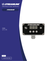
SFC5

Streamline SFC5 User manual

  • Hello! I've reviewed the STREAMLINE SFC5 Digital Controller Instruction Manual. This manual provides detailed instructions on how to use the controller, including priming, adjusting dead-end detection and interpreting controller messages. I'm ready to answer any questions you have about setting it up or its operation.
  • What does 'dead-end detection' mean?
    How do I adjust the dead-end detection sensitivity?
    What does the 'Bat' message mean?
    What is the maximum pump drive current?
W: www.streamline.systems E: sales@streamline.systems T: +44 (0)1626 830 830 W: www.streamline.systems E: sales@streamline.systems T: +44 (0)1626 830 830 1
STREAMLINE
®
INSTRUCTION
MANUAL
STREAMLINE
SFC5
STREAMLINE® SFC5
Digital Controller
Codes:
Kit Includes:
INSTR-SFC5
®
2W: www.streamline.systems E: sales@streamline.systems T: +44 (0)1626 830 830 W: www.streamline.systems E: sales@streamline.systems T: +44 (0)1626 830 830 3
STREAMLINE
®
STREAMLINE® systems can be built according to customers’ exact requirements
For non-standard systems, the user’s needs or specifications are listened to and turned
into reality.
Whilst price is important, quality is remembered long after price is forgotten
We insist on sourcing brand name products from around the world, only of a reputable
quality, and bring them together under the STREAMLINE® name
All STREAMLINE® products carry a full one year’s warranty, according to the manufacturers’
standard terms and conditions of sale.
We have an in-house technical helpline able to answer most of your questions relating to the
capabilities and functionalities of all STREAMLINE® products
If we get it wrong, we will put it right. If you are sent a wrong item, we will immediately
attend to sending you the correct item and arrange a collection of the wrong item without
any quibbles
STREAMLINE® is backed by a comprehensive range with massive stocks providing you with a
‘one stop shop’ for all your requirements.
Flexibility
Quality
Service
Why STREAMLINE®?
STREAMLINE® Warranty
MANUFACTURED
IN THE
UNITED KINGDOM
CHECKED AND
TESTED BY
QUALITY CONTROL
The warranty on all Machines and Equipment is
for 1 year (12-months) from RECORDED DATE
OF PURCHASE.
THIS WARRANTY EXCLUDES NORMAL
MAINTENANCE ITEMS, including but not limited
to HOSES, FILTERS, O-RINGS,
DIAPHRAGMS, VALVES, GASKETS,
CARBON BRUSHES and damage to motors
and other components as a result of failure to
replace normal maintenance items. THIS LIST
IS NOT EXHAUSTIVE.
If STREAMLINE® receives notice of such defects
during the warranty period, STREAMLINE®
will either, at its opinion, repair or replace
components which prove to be defective.
Replacement parts will only be supplied under
warranty, upon the inspection and approval of
the defective parts by STREAMLINE®.
Should it be necessary to supply replacement
parts before the opportunity to inspect, these
will be charged at current prices and credit will
only be issued upon subsequent inspection and
warranty approval by STREAMLINE®.
The customer is responsible for the cost of
return of the defective part. If warranty is
approved, STREAMLINE® will pay for the cost
of the repaired or replacement part.
This warranty excludes the following conditions
and circumstances which are at the discretion
of STREAMLINE®:
Wear and tear, misuse, abuse improper
maintenance, frost damage, the use of chemicals
other than those supplied or approved by
STREAMLINE®, improper installation or repair,
unauthorised modification, incidental or
consequential costs, loss or damage, service,
labour or third party charges, the cost of
returning defective parts to STREAMLINE®.
This warranty constitutes the exclusive remedy
of any purchaser of a STREAMLINE® unit and
is in lieu of all other warranties, express or
implied, including without limitation any implied
warranty of merchantability or fitness for use, to
the fullest extent permitted by law. In no event
shall any implied warranty of merchantability or
fitness for use exceed the term of the applicable
warranty stated above and STREAMLINE® shall
have no other obligation or liability.
Important
Unfortunately these rights cannot be
transferred to a third party.
4W: www.streamline.systems E: sales@streamline.systems T: +44 (0)1626 830 830 W: www.streamline.systems E: sales@streamline.systems T: +44 (0)1626 830 830 5
STREAMLINE
®
To turn on the unit, press Up arrow or Down arrow The unit will ramp up to the last pump
setting. The pump setting is indictated as a value from 0-99.
To adjust dead-end detection, press and hold and at the same time. Wait for ‘Cal’ to display
on the screen. The pump will continue to drive at its current value.
When ‘Cal’ displays on the screen, adjust dead-end detection up with (less sensitive,turns o at
higher pressures) or down with (more sensi-tive, turns o at lower pressures).
When you are happy with the setting, press Enter button
After filling your water tanks you must prime your system by pumping all the air from the hoses
To turn up the pump, press in single steps or press and hold to accelerate.
To see the battery voltage, press Enter button The voltage is displayed as a 3-digit number e.g.
‘12.5’ (the unit is volts). Press again to go back to the pump setting.
To turn o the unit, press and hold Enter button
cuts resin use to a minimum by giving
the operator fine control overflow rates
controls the water to pump -fed pole
systems accurately and dependably
extends the life of resin cartridges
allows fine pump control 0-99
displays battery voltage
has easy to set up dead-end detection
Child’s play to use…
Coping easily with demanding daily use,
the STREAMLINE® controller:
Operation
Operating & Specifications Priming Your System
Specifications
Adjusting Dead End Detection
The unit is supplied in a robust ABS case as standard. All the connectors are of a tough, hard wearing
design. The unit is sealed to IP63 to prevent water ingress. The electronics are protected from mechanical
shock and moisture.
The controller is capable of driving pumps rated up to 10A from standard 12V vehicle battery.
The STREAMLINE® controller can shut down the pump automatically when the flow is stopped by
something like a kink in the hose or when the pole is removed (should you have cut-o EZ snap
connectors). This is called a ‘Dead -End’. This feature is useful as it prevents build-up of pressure in a
system and so minimises the risk of blown hoses and fittings. It also reduces the wear on the pump. We
call this feature ‘Dead-End Detection ‘.
However, the sensitivity must be set by the user. This is to prevent the unit turning o too early (for
instance as a system pressures up) or too late (when you may start blowing hoses).
It has simple to use controls through a three button interface. Unit status is indicated on the three
digit display.
Electrical Specification Value Mechanical Specification Value
Supply voltage 6-25V Enclosure material ABS
Maximum pump drive current 10A Water resisance IP65
Typical drive current 2-3A Dimensions (mm) 115x65x40
Working temperature 0°C-40°C Voltmeter reading ± 100mV
6W: www.streamline.systems E: sales@streamline.systems T: +44 (0)1626 830 830 W: www.streamline.systems E: sales@streamline.systems T: +44 (0)1626 830 830 7
STREAMLINE
®
PS – Pressure switch has activated. You must reduce
pressure to allow the pump to re-start.
DE – A dead-end has been detected. The pump has
been turned o automatically by the controller.
Bat (Pump still working) – Your battery voltage has
dropped below 11.5V.
Re-charge your battery as soon as possible
Bat (Flashing and pump stopped) – Your battery
voltage has dropped be-low 11.0V. T h e pump has been
stopped by the controller to prevent pos-sible damage
to the battery. Re-charge your battery as soon
as possible.
Message Description
Controller Messages Operating Warnings
1. Adjust your flow settings carefully. Repeated false dead-end detection indicates that the
dead-end detection should be turned up (less sensitive).
2. For absolute safety always wire through the pump pressure switch. (The pressure switch
can be by passed if absolutely necessary - the unit will protect itself under
normal conditions.)
3. The controller is a WATER PUMP controller: it will not work with air in the system.
Always prime your system before starting work. If air in the system causes false dead- end detection, turn
dead-end detection up (less sensitive).
8W: www.streamline.systems E: sales@streamline.systems T: +44 (0)1626 830 830 W: www.streamline.systems E: sales@streamline.systems T: +44 (0)1626 830 830 9
STREAMLINE
®
Fitting Instructions
1. Follow these instructions carefully. Always use a qualified electrician for electrical
installation. The warranty is void if the unit is damaged through in correct connection or
use. STREAMLINE® recommends all cables are run through insulating conduit.
2. Fit the STREAMLINE® controller to a surface securely using M3 bolts through the wells
provided. Do not connect the electrical connections to the STREAMLINE® controller.
3. Ensure the pump is mounted securely. Connect the fuses as indicated in the connection
diagrams. DO NOT INSTALL FUSES IN THE FUSE-H HOLDERS yet.
4. Connect the power wires to the pump: Red (3) to +POSITIVE terminal, Black (4) to
– NEGATIVE terminal.
5. Connect the power wires to the battery: Red (1) to +POSITIVE terminal, Black (2) to
– NEGATIVE terminal.
6. Install the fuses in the fuse-holders now. The unit should now power up when either or
are pressed.
Pump
Vehicle
Earth
SFC5 Controller
Second
Battery
Fuse 7.5A Red 6m
Red 2m Black 6m Black 2m
Hamilton House, 8 Fairfax Road,
Heathfield Industrial Estate,
Newton Abbot
Devon, TQ12 6UD
United Kingdom
Telephone: +44 (0) 1626 830 830
Email: sales@streamline.systems
Visit www.streamline.systems
INSTR-SFC5
/