Kichler 59112OZ User manual

Type
User manual

Kichler 59112OZ is a versatile lighting fixture designed for both indoor and outdoor use. With its adjustable mounting strap, it can be installed on a variety of surfaces, making it suitable for various applications. The fixture is compatible with a wide range of bulb types, including incandescent, fluorescent, and LED, offering flexibility in creating the desired lighting ambiance. Its sturdy construction and weather-resistant design ensure durability and longevity, even in harsh outdoor conditions.

Kichler 59112OZ is a versatile lighting fixture designed for both indoor and outdoor use. With its adjustable mounting strap, it can be installed on a variety of surfaces, making it suitable for various applications. The fixture is compatible with a wide range of bulb types, including incandescent, fluorescent, and LED, offering flexibility in creating the desired lighting ambiance. Its sturdy construction and weather-resistant design ensure durability and longevity, even in harsh outdoor conditions.

For warranty information please visit: kichler.com/warranty
REV 7-MAR-2023
We’re here to help 866-558-5706
Hrs: M-F 9am to 5pm EST
CAUTIONS
CAUTION – RISK OF SHOCK:
Disconnect Power at the main circuit breaker panel or main fusebox before starting and during
the installation.
WARNING:
1. This fixture is intended for installation in accordance with the National Electrical Code (NEC)
and all local code specifications. If you are not familiar with code requirements, installation by a
certified electrician is recommended. Failure to adhere to these codes and instructions may result
in serious injury and/or property damage and will void the warranty.
INSTRUCTIONS FOR MOUNTING FIXTURE OUTDOORS
AND/OR IN WET LOCATIONS:
1) Mounting surface should be clean, dry, flat and 1/4” larger than the canopy on all sides. Any gaps
between the mounting surface and canopy exceeding 3/16” should be corrected as required.
2) With silicone caulking compound, caulk completely around where back of canopy meets the wall
surface to prevent water from seeping into outlet box.
CLEANING:
• Always be certain that electric current is turned o before cleaning.
• Only a soft damp cloth should be used. Harsh cleaning products may damage the finish.
INSTALLATION INSTRUCTIONSFIXTURE DIAGRAM
IS-59111-US
PARTS LIST
[A] Mounting Strap
[B] Outlet Box (not supplied) [C] Strap Mounting Screw (2)
[D] Mounting Screw (4) [E] Socket
[F] Canopy
1. Attach mounting strap[A] to outlet box[B] using the strap mounting
screws[C]. Mounting strap can be adjusted to suit position of fixture.
NOTE: Mounting strap should be installed with the bent tabs at the outer
edge of the mounting strap pointing away from the wall, at the 9 and 3
o’clock position as shown.
2. Grounding instructions: (See Illus. a or b).
a. On fixtures where mounting strap is provided with a hole and two
raised dimples, wrap ground wire from outlet box around green
ground screw, and thread into hole.
b. On fixtures where a cupped washer is provided, attach ground wire
from outlet box under cupped washer and green ground screw, and
thread into mounting strap.
If fixture is provided with ground wire, connect fixture ground wire to
outlet box ground wire with wire connector after following the above
steps. Never connect ground wire to black or white power supply wires.
3. Make wire connections. Reference chart below for correct connections
and wire accordingly.
Connect Black or Red
Supply Wire to:
Connect White Supply
Wire to:
Black White
*Parallel cord (round &
smooth)
*Parallel cord (square &
ridged)
Clear, Brown, Gold or Black
without Tracer
Clear, Brown, Gold or Black
with Tracer
Insulated wire (other
than green) with copper
conductor
Insulated wire (other
than green) with silver
conductor
*Note: When parallel wire (SPT
1 & SPT 2) are used. The neutral
wire is square shaped or ridged
and the other wire will be round
in shape or smooth (See illus.) Neutral Wire
4. NOTE: Fixture should be installed with socket[E] facing DOWN as
shown.
Push canopy[F] to wall, carefully aligning the mounting screw holes in left
and right side of mounting strap with the mounting screw holes in left and
right side of canopy.
NOTE: Make sure all wires are inside canopy and do not get pinched
between mounting strap and canopy or wall and canopy of fixture.
5. Screw four (4) mounting screws[D] into holes in canopy and mounting
strap to attach fixture to wall. Two on the left side and two on the right
side of canopy. Tighten to secure.
6. Insert recommended bulb(s) (not included).
GREEN GROUND
SCREW
CUPPED
WASHER
OUTLET BOX
GROUND
FIXTURE
GROUND
DIMPLES
WIRE CONNECTOR
OUTLET BOX
GROUND
GREEN GROUND
SCREW
FIXTURE
GROUND
ab
© 2023 Kichler Lighting LLC. All rights reserved.
B
A
C
D
F
E
REV 7-MAR-2023
PRÉCAUTIONS
ATTENTION – RISQUE DE DÉCHARGES ÉLECTRIQUES :
Couper le courant au niveau du panneau du disjoncteur du circuit principal ou de la boîte à fusibles
principale avant de procéder à l’installation.
ATTENTION :
1. Ce luminaire doit être installé conformément aux codes d’électricité nationaux (NEC) et satisfaire
toutes les spécifications des codes locaux. Si vous ne connaissez pas les exigences de ces codes,
il est recommandé de confier l’installation à un électricien certifié. Ne pas se conformer à ces
codes et directives pourrait provoquer des blessures sérieuses et/ou des dommages matériels et
rendre la garantie non valide.
INSTRUCTIONS POUR LE MONTAGE DU LUMINAIRE À L’EXTÉRIEUR ET/OU DANS DES
ENDROITS HUMIDES :
1) La surface de montage doit être propre, sèche, plate et plus grande de 1/4 po que le cache de tous
les côtés. Tout espace entre la surface de montage et le cache qui a plus de 3/16 po de haut devrait
être corrigée au besoin.
2) À l’aide d’un produit de calfeutrage au silicon, calfeutrer avec soin et complètement à l’endroit où
l’arrière du cache rencontre la surface du mur pour empêcher l’eau de pénétrer dans le boîtier.
NETTOYAGE :
• Soyez toujours certain que l’alimentation électrique du luminaire est fermée avant le nettoyage.
• N’utilisez qu’un chion doux humide. Les produits de nettoyage acides/abrasifs peuvent
endommager le fini.
INSTRUCTIONS DINSTALLATION
DIAGRAMME D’APPAREILS
IS-59111-CB
INSTRUCTIONS:
For Assembling and Installing Fixtures in Canada
Pour L’assemblage et L’installation Au Canada
Nous sommes là pour vous aider 866-558-5706
Heures : du lundi au vendredi, de 9h à 17h (heure de l’Est)
Pour de plus amples informations sur la garantie, veuillez visiter : kichler.com/warranty
LISTE DES PIÈCES
[A] Étrier de Montage
[B] Boite à Prises (non fournie) [C] Vis de Montage de L’étrier (2)
[D] Vis de Montage (4) [E] Douille
[F] Cache
1. Fixer l’étrier de montage[A] sur la bte à prises[B] à l’aide des vis de
fixation de l’étrier[C]. L’étrier de montage peut être réglé en fonction de la
position du luminaire.
REMARQUE : Installer l’étrier de montage avec les attaches recourbées
situées sur le bord externe de l’étrier et pointant dans le sens oppose au
mur, en position de 9 et 3 heures (voir illustration).
2. Connecter les fils. Se reporter au tableau ci-dessous pour faire les
connexions.
Connecter le fil noir ou
rouge de la boite
Connecter le fil blanc de
la boîte
A Noir A Blanc
*Au cordon parallèle (rond
et lisse)
*Au cordon parallèle (à
angles droits el strié)
Au transparent, doré,
marron, ou noir sans fil
distinctif
Au transparent, doré,
marron, ou noir avec un til
distinctif
Fil isolé (sauf fil vert) avec
conducteur en cuivre
Fil isolé (sauf fil vert) avec
conducteur en argent
*Remarque: Avec emploi d’un
fil paralléle (SPT 1 et SPT 2). Le
fil neutre est á angles droits ou
strié et l’autre fil doit étre rond ou
lisse (Voir le schéma). Fil Neutre
3. REMARQUE : Le luminaire devrait être installé avec la douille[E]
orientée vers le BAS tel qu’illustré.
Placez le cache[F] contre le mur, en alignant soigneusement les trous de
vis de montage sur les côtés gauche et droit de l’étrier de montage avec
les trous de vis de montage sur les côtés gauche et droit du cache.
REMARQUE : S’assurer que tous les fils sont à l’intérieur du cache et
ne sont pas coincés entre l’étrier de montage et le cache ou le mur et le
cache du luminaire.
4. Vissez quatre (4) vis de montage[D] dans les trous du cache et de l’étrier
de montage pour fixer le luminaire au mur. Deux du côté gauche et deux
du côté droit du cache. Serrez pour fixer.
5. Installez les ampoules recommandées (non fournies).
© 2023 Kichler Lighting LLC. Tous droits réservés.
B
A
C
D
F
E
IS-59111-USREV 7-MAR-2023
PRECAUCIONES
PRECAUCIÓN – RIESGO DE DESCARGA ELÉCTRICA:
Desconecte la electricidad en el panel principal del interruptor automático o caja principal de
fusibles antes de comenzar y durante la instalación.
ADVERTENCIA:
1. Este accesorio está destinado a la instalación de acuerdo con el National Electrical Code (NEC)
y todas las especificaciones del código local. Si no está familiarizado con los requisitos del
código, la instalación se recomienda un electricista certificado. No cumplir con estos códigos e
instrucciones puede resultar en lesiones graves y/ o en daños a la propiedad y anulará la garantía.
INSTRUCCIONES PARA EL MONTAJE DEL ARTEFACTO AL AIRE LIBRE Y/O EN LUGARES
HÚMEDOS:
1) La superficie de montaje debe estar limpia, seca, plana y 1/4 “ más grande que el escudete en
todos los lados. Cualquier espacio entre la superficie de montaje y el escudete que exceda 3/16”
debe ser corregido según sea necesario.
2) Con silicona para calafatear, calafatee completamente alrededor de donde la parte posterior del
escudete se encuentra con la superficie de la pared para evitar que el agua se filtre dentro de la
caja de distribución.
LIMPIEZA:
• Asegúrese siempre de que la corriente eléctrica esté apagada antes de limpiar.
• Debe usarse solamente un paño húmedo y suave. Productos de limpieza abrasivos pueden
dañar el acabado.
INSTRUCCIONES DE INSTALACIÓN
DIAGRAMA DE ACCESORIOS
Estamos aquí para ayudarle 866-558-5706
Horario: Lunes-Viernes 9am a 5pm EST (hora oficial del este)
Para informacion de la garantia por favor visite: kichler.com/warranty
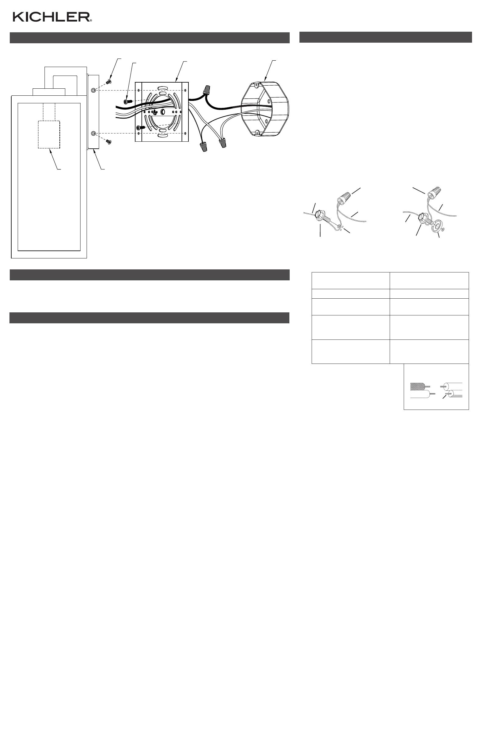
LISTA DE PARTES
[A] Abrazadera de Montaje
[B] Caja de Salida (no
suministrada)
[C] Tornillo de Montaje de la
Abrazadera (2)
[D] Tornillo de Montaje (4)
[E] Portalámparas
[F] Cubierta
1. Acople la abrazadera de montaje[A] a la caja de salida[B] con los tornillos
de montaje de la abrazadera[C]. La abrazadera de montaje se puede
ajustar para acomodar la posición del artefacto.
NOTA: La abrazadera de montaje debe instalarse con las lengüetas
dobladas en el borde exterior de la abrazadera de montaje apuntando
hacia afuera de la pared, y en la posición de las 9 y las 3 en punto, como se
muestra.
2. Instrucciones de conexión a tierra solamente para los Estados Unidos.
(Vea la ilustracion a o b).
a. En las lámparas que tienen la abrazadera de montaje con un agujero
y dos hoyuelos realzados, enrollar el alambre a tierra de la caja de
salida alrededor del tornillo verde y pasarlo por el aquiero.
b. En las lámparas con una arandela acopada, fijar el alambre a tierra
de la caja de salida del ajo de la arandela acoada y tornillo verde, y
paser por a abrazadera de montaje.
Si la lámpara viene con alambre a tierra, conecter el alambre a tierra
de la lámpara al alambre a tierra de la caja de salida con un conector
de alambres espués de seguir los pasos anteriores. Nunca conectar el
alambra a tierra a los alambres eléctros negro o blanco.
3. Haga les conexiones de los alambres. La tabla de referencia de abajo
indica las conexiones correctas y los alambres correspondientes.
Conectar el alambre de
suministro negro o rojo al
Conectar el alambre de
suministro blanco al
Negro Blanco
*Cordon paralelo (redondo
y liso)
*Cordon paralelo (cuadrado
y estriado)
Claro, marrón, amarillio
o negro sin hebra
identificadora
Claro, marrón, amarillio
o negro con hebra
identificadora
Alambre aislado (diferente
del verde) con conductor
de cobre
Alambre aislado (diferente
del verde) con conductor
de plata
*Nota: Cuando se utiliza alambre
paralelo (SPT 1 y SPT 2). El
alambre neutro es de forma
cuadrada o estriada y el otro
alambre será de forma redonda o
lisa. (Vea la ilustracíón). Hilo Neutral
4. NOTA: El artefacto debe instalarse con el portalámparas[E] hacia
ABAJO, tal como se muestra.
Empuje la cubierta[F] a la pared, alineando con cuidado los orificios de
los tornillos de montaje en el lado izquierdo y derecho de la abrazadera de
montaje con los orificios de los tornillos de montaje en el lado izquierdo y
derecho de la cubierta.
NOTA: Asegúrese de que todos los cables estén dentro de la cubierta y
no queden apretados entre la abrazadera de montaje y la cubierta o la
pared y la cubierta del artefacto.
5. Atornille cuatro (4) tornillos de montaje[D] en los orificios de la cubierta y
de la abrazadera de montaje para fijar el artefacto a la pared. Dos del lado
izquierdo y dos del lado derecho de la cubierta. Apriete para asegurar.
6. Inserte los focos recomendados (no incluidos).
ARANDELA
CONCAVA
TIERRA DE LA
CAJA DE SALIDA
TORNILLO DE TIERRA,
VERDE
DEPRESIONES
TIERRA
ARTEFACTO
CONECTOR DE ALAMBRE
TIERRA DE LA
CAJA DE SALIDA
TORNILLO DE TIERRA,
VERDE
TIERRA
ARTEFACTO
ab
© 2023 Kichler Lighting LLC. Todos los derechos reservados.
B
A
C
D
F
E
  • Page 1 1
  • Page 2 2
  • Page 3 3

Kichler 59112OZ User manual

Type
User manual

Kichler 59112OZ is a versatile lighting fixture designed for both indoor and outdoor use. With its adjustable mounting strap, it can be installed on a variety of surfaces, making it suitable for various applications. The fixture is compatible with a wide range of bulb types, including incandescent, fluorescent, and LED, offering flexibility in creating the desired lighting ambiance. Its sturdy construction and weather-resistant design ensure durability and longevity, even in harsh outdoor conditions.

Ask a question and I''ll find the answer in the document

Finding information in a document is now easier with AI