
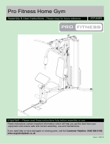
THIS INSTRUCTION BOOKLET CONTAINS IMPORTANT SAFETY INFORMATION. PLEASE READ AND KEEP FOR FUTURE REFERENCE.
‐ Unit can tip over causing severe injury or death.
‐ Anchor unit to stud in wall (if instructed to).
‐ Do Not allow children to climb on unit.
‐ Put heavy items on lower shelves or drawers.
Assembly Di�culty Meter
Easy Tough

ABC
F1 F2
D
1
2 3
Parts assembly diagram
All asterisks follow the installation process above
×27 ×273.5*40 15*11.5mm mm
F1:3*16mm ×12
E
G
×2
H
mm ×2
4*18
×16 ×6
F2: mm ×244*16
×1

Plate splitting diagram

A B
installation drawing 1
×6 ×6
15*11.5
3.5*40mm mm
A
A
A
A
B
B
B
B
8
5
8
51
2
AB
A
B
Screw A into the embedded hole of No. 2 plate,
put No. 2 plate flat, insert No. 5 plate and No.
8 plate into A, and finally lock it with B.
Screw A into No. 1 board, connect No. 5 board and No. 8 board, and lock it with B.
2
Connect

15
1
2
11
12
B
B
A
A
installation drawing 2
B
A
AA B
×3 ×3
15*11.5
3.5*40mm mm
Insert No. 15 plate into the slots of No. 1 plate and No. 2 plate
Screw A into No. 11 plate, connect No. 12 plate, lock with B

installation drawing 3
A
AA
B
B
B
3
4
13
12
11
AA B
×10 ×10
15*11.5
3.5*40mm mm
A
A
A
B
B
B
3
13
12
11
B
B
A
B
Screw A into the embedded hole of No.3 plate,
connect No.11 and No.12 plate with No.3 plate,
then connect No.13 plate with No.3 plate, and
finally lock it with B
Connect plate No. 4 to plate 11,12.13 and lock with B

installation drawing 4
AA
×8
3.5*40mm
3
4
14
AA
A
AA
A
A
A
7
Insert No. 14 plate into slots of No. 3 plate and No. 4 plate
Screw A into board 7

installation drawing 5
G
×16
B
B
BB
B
BBB
B
×8
15*11.5mm
7
1
2
3
4
15
14
Connect the two frames assembled above to the No.7 plate,With lock B
Insert G into the inner hole of the plate

installation drawing 6
10
6
6
6
9
DE
C
C
F1
F1
C
×2
F1
F1:3*16mm ×4
DE
mm ×2
4*18
×1
Put three No.6 boards and No.10 boards in the cupboard
Fix handle D on No. 9 plate with E, and fix handle
C on the round hole of No. 9 plate with F1

installation drawing 7
F3
F3
F3
F3
F3
F1
F1:3*16mm ×8
F3
F3: mm ×244*16
H
×6
H
HH
H
H
Connect the fixed C in plate 9 to plate 1 with F1
F1
Connect foot H to bottom of No.7 plate with F3
F3
H

-
 1
1
-
 2
2
-
 3
3
-
 4
4
-
 5
5
-
 6
6
-
 7
7
-
 8
8
-
 9
9
-
 10
10
-
 11
11


FUFU GAGA DRF-KF310016-01-sd User manual
- Type
- User manual
- This manual is also suitable for
Ask a question and I''ll find the answer in the document
Finding information in a document is now easier with AI
Related papers
Other documents
-
York Fitness G510 User manual
-
 Argos pro fitness User manual
-
Weider 240 TC User manual
-
 Wharfedale Pro EVO30 User manual
-
Viper Fang 32T Owner's manual
-
Wharfedale EVO 30 User manual
-
Cal-Royal CAL-ROYAL 500 Series Grade 1 Door Closer Installation guide
-
Weslo WLEX91408.0 User manual
-
-
Dodge Sleeveoil M-Series Center Flange Bearing Owner's manual

