Page is loading ...

Vacuum spray degassing 06.07.2016 - Rev. B
Servitec 30
GB
Operating manual
Original operating manual


Contents
Vacuum spray degassing — 06.07.2016 - Rev. B English —
3
English
Vacuum spray degassing
06.07.2016 - Rev. B
Contents
1
Notes on the operating manual..................................................................................................................................................... 5
2
Liability and guarantee................................................................................................................................................................... 5
3
Safety................................................................................................................................................................................................ 6
3.1 Explanation of symbols ........................................................................................................................................................................ 6
3.2 Personnel requirements ...................................................................................................................................................................... 7
3.3 Personal protective equipment .......................................................................................................................................................... 7
3.4 Intended use .......................................................................................................................................................................................... 7
3.5 Inadmissible operating conditions..................................................................................................................................................... 7
3.6 Residual risks ......................................................................................................................................................................................... 8
4
Description of the device................................................................................................................................................................ 9
4.1 Description ............................................................................................................................................................................................. 9
4.2 Overview ................................................................................................................................................................................................ 9
4.3 Identification ....................................................................................................................................................................................... 10
4.4 Function ............................................................................................................................................................................................... 10
4.5 Scope of delivery ................................................................................................................................................................................. 13
4.6 Optional equipment and accessories .............................................................................................................................................. 13
5
Technical data ............................................................................................................................................................................... 14
5.1 Electrical system .................................................................................................................................................................................. 14
5.2 Dimensions and connections ............................................................................................................................................................ 14
5.3 Operation ............................................................................................................................................................................................. 14
6
Installation ..................................................................................................................................................................................... 16
6.1 Installation conditions ....................................................................................................................................................................... 17
6.1.1 Incoming inspection ....................................................................................................................................................... 17
6.2 Preparatory work ................................................................................................................................................................................ 17
6.3 Execution .............................................................................................................................................................................................. 18
6.3.1 Fitting the add-on components .................................................................................................................................... 19
6.3.2 Wall mounting ................................................................................................................................................................. 19
6.3.3 Hydraulic connection ...................................................................................................................................................... 20
6.4 Switching and make-up variants ...................................................................................................................................................... 23
6.4.1 Pressure-dependent "Magcontrol" make-up mode ................................................................................................... 23
6.4.2 Level dependent "Levelcontrol" make-up mode ....................................................................................................... 24
6.5 Electrical connection .......................................................................................................................................................................... 25
6.5.1 Terminal diagram ............................................................................................................................................................ 26
6.5.2 RS-485 interface............................................................................................................................................................... 28
6.6 Installation and commissioning certificate ..................................................................................................................................... 29
7
Commissioning.............................................................................................................................................................................. 30
7.1 Checking the requirements for commissioning ............................................................................................................................. 30
7.2 Setting the minimum operating pressure for Magcontrol ........................................................................................................... 30
7.3 Filling the device with water ............................................................................................................................................................. 31
7.4 Modifying the controller's start routine .......................................................................................................................................... 32
7.5 Starting Automatic mode .................................................................................................................................................................. 33
8
Operation ....................................................................................................................................................................................... 34
8.1 Operating modes ................................................................................................................................................................................ 34
8.1.1 Automatic mode .............................................................................................................................................................. 34
8.1.2 Manual mode ................................................................................................................................................................... 35
8.1.3 Stop mode ........................................................................................................................................................................ 35
8.1.4 Summer operation .......................................................................................................................................................... 36

Contents
4 — English Vacuum spray degassing — 06.07.2016 - Rev. B
8.1.5 Restarting ......................................................................................................................................................................... 36
9
Controller ...................................................................................................................................................................................... 37
9.1 Operator panel .................................................................................................................................................................................... 37
9.2 Customer menu .................................................................................................................................................................................. 38
9.3 Service menu ....................................................................................................................................................................................... 38
9.4 Default settings ................................................................................................................................................................................... 39
9.5 Parametrising the controller in the Customer menu .................................................................................................................... 40
9.6 Messages .............................................................................................................................................................................................. 44
10
Maintenance ................................................................................................................................................................................. 47
10.1 Maintenance schedule ....................................................................................................................................................................... 48
10.2 Cleaning ............................................................................................................................................................................................... 49
10.2.1 Cleaning the dirt trap ...................................................................................................................................................... 49
10.3 Maintenance certificate ..................................................................................................................................................................... 50
11
Disassembly .................................................................................................................................................................................. 51
12
Annex ............................................................................................................................................................................................ 53
12.1 Reflex Customer Service .................................................................................................................................................................... 53
12.2 Conformity and standards ................................................................................................................................................................. 54
12.3 Guarantee ............................................................................................................................................................................................ 55

Notes on the operating manual
Vacuum spray degassing — 06.07.2016 - Rev. B English —
5
1
Notes on the operating manual
This operating manual is an important aid for ensuring the safe and reliable functioning of the device.
The operating manual will help you to:
• avoid any risks to personnel.
• become acquainted with the device.
• achieve optimal functioning.
• identify and rectify faults in good time.
• avoid any faults due to improper operation.
• cut down on repair costs and reduce the number of downtimes.
• improve the reliability and increase the service life of the device.
• avoid causing harm to the environment.
Reflex Winkelmann GmbH accepts no liability for any damage resulting from failure to observe the information in this operating manual.
In addition to the requirements set out in this operating manual, national statutory regulations and provisions in the country of
installation must also be complied with (concerning accident prevention, environment protection, safe and professional work practices,
etc.).
This operating manual describes the device with basic equipment and interfaces for optional equipment with additional functions. For
optional equipment and accessories, see chapter 4.6 "Optional equipment and accessories" on page 13 .
Note!
Every person installing this equipment or performing any oth
er work at the equipment is required to carefully read this
manual prior to commencing work and to comply with its instructions. The manual is to be provided to the device operator
and must be stored near the device for access at any time.
2
Liability and guarantee
The device has been built according to the state of the art and recognised safety rules. Nevertheless, its use can pose a risk to life and
limb of personnel or third persons as well as cause damage to the system or other property.
It is not permitted to make any modifications at the device, such as to the hydraulic system or the circuitry.
The manufacturer shall not be liable nor shall any warranty be honoured if the cause of any claim results from one or more of the
following causes:
• Improper use of the device.
• Unprofessional commissioning, operation, service, maintenance, repair or installation of the device.
• Failure to observe the safety information in this operating manual.
• Operation of the device with defective or improperly installed safety/protective equipment.
• Failure to perform maintenance and inspection work according to schedule.
• Use of unapproved spare parts or accessories.
Prerequisite for any warranty claims is the professional installation and commissioning of the device.
Note!
Arrange for Reflex Customer Service to carry out commissioning and annual maintenance, see chapter
12.1 "Reflex
Customer Service
" on page 53 .

Safety
6
— English Vacuum spray degassing — 06.07.2016 - Rev. B
3
Safety
3.1
Explanation of symbols
The following symbols and signal words are used in this operating manual.
DANGER
Danger of death and/or serious damage to health
• The sign, in combination with the signal word 'Danger', indicates imminent danger; failure to observe the safety information will
result in death or severe (irreversible) injuries.
WARNING
Serious damage to health
• The sign, in combination with the signal word 'Warning', indicates imminent danger; failure to observe the safety information can
result in death or severe (irreversible) injuries.
CAUTION
Damage to health
• The sign, in combination with the signal word 'Caution', indicates danger; failure to observe the safety information can result in
minor (reversible) injuries.
ATTENTION
Damage to property
• The sign, in combination with the signal word 'Attention', indicates a situation where damage to the product itself or objects within
its vicinity can occur.
Note!
This symbol, in combination with the signal word 'Note', indicates useful tips and recommendations for efficient handling
of the product.

Safety
Vacuum spray degassing — 06.07.2016 - Rev. B English —
7
3.2
Personnel requirements
Only specialist personnel or specifically trained personnel may install and operate the equipment.
The electric connections and the wiring of the device must be executed by a specialist in accordance with all applicable national and
local regulations.
3.3
Personal protective equipment
When working at the system, wear the stipulated personal equipment such as hearing and eye protection, safety boots, helmet,
protective clothing, protective gloves.
See the national regulation of your country for personal protective equipment required.
3.4
Intended use
The device is used in plant systems for stationary heating and cooling circuits. The devices may be used only in systems that are sealed
against corrosion and with the following water types:
• Non-corrosive.
• Chemically non-aggressive.
• Non-toxic.
Minimise the entry of atmospheric oxygen throughout the plant system and into the make-up water.
Note!
Ensure the quality of the make
-up water as specified by national regulations.
–
For example, VDI 2035 or SIA 384-1.
Note!
•
To ensure fault-free operation of the system for the long-term, glycols whose inhibitors prevent corrosion
phenomena must always be used for systems operating with water/glycol mixtures. It must also be ensured that no
foam is formed due to the substances in the water. Otherwise this could endanger the entire function of the vacuum
spray tube degassing as this can lead to sedimentation in the vent pipe and therefore leaks.
•
The specifications of the respective manufacturer are always decisive for the specific properties and mixing ratio of
the water/glycol mixtures.
•
Types of glycol must not be mixed and the concentration is generally to be checked every year (see manufacturer
information).
3.5
Inadmissible operating conditions
The device is not suitable for the following applications:
• Outdoor operation.
• For the use with mineral oils.
• For the use with flammable media.
• For the use with distilled water.
Note!
It is not permitted to make any modifications to the hydraulic system or the circuitry.

Safety
8
— English Vacuum spray degassing — 06.07.2016 - Rev. B
3.6
Residual risks
This device has been manufactured to the current state of the art. However, some residual risk cannot be excluded.
CAUTION
Risk of burns on hot surfaces
Hot surfaces in heating systems can cause burns to the skin.
• Wear protective gloves.
• Please place appropriate warning signs in the vicinity of the device.
CAUTION
Risk of injury due to pressurised liquid
If installation, removal or maintenance work is not carried out correctly, there is a risk of burns and other injuries at the connection
points, if pressurised hot water or hot steam suddenly escapes.
• Ensure proper installation, removal or maintenance work.
• Ensure that the system is de-pressurised before performing installation, removal or maintenance work at the connection points.
CAUTION
Risk of injury upon coming into contact with glycol containing water
Contact with glycol containing water in plant systems for cooling circuits can result in irritation of the skin and eyes.
• Use personal protective equipment (safety clothing, gloves and goggles, for example).
CAUTION
Risk of injury due to heavy device weight
The device weight may cause physical injury or accidents.
• If necessary, work with a second person during assembly or disassembly.
ATTENTION
Device damage during transport
Improper transporting procedures can cause damage to the connections for degassing and makeup lines.
• Use suitable covers to protect the connections against damage.
• Only transport the device in an upright position.
ATTENTION
Property damage during transport
Improper transporting procedures may cause damage.
• Fasten the device with suitable transport securing means such as straps.

Description of the device
Vacuum spray degassing — 06.07.2016 - Rev. B English —
9
4
Description of the device
4.1
Description
The device is a degassing and make-up station. Its main areas of application are heating and cooling circuits and systems in which
interruptions of operations due to dissolved or free gases. The device works only with a vacuum pump designed for this purpose. This
design enables a compact footprint for small and mid-sized systems.
The device provides the following safety features:
• No direct intake of air thanks to a regulation of the pressure maintenance with automatic make-up.
• No circulation issues caused by free bubbles in the circuit water.
• Reduced corrosion damage due to oxygen removal from fill and make-up water.
4.2
Overview
1 Controller 6 "PIS" pressure transducer
2 Venting grille 7 "PU" vacuum degassing pump
3 "ST" dirt trap 8 Removable front shell
4 "DV" degassing valve WC Make-up connection
5 "CD" 3-ways motor ball valve for the hydraulic regulation
of system and make-up degassing
DC Degassing connection
• Gas-rich water inlet
• Degassed water outlet

Description of the device
10
— English Vacuum spray degassing — 06.07.2016 - Rev. B
4.3
Identification
The nameplate provides information about the manufacturer, the year of manufacture, the manufacturing number and the technical
data.
Information on nameplate
Meaning
Type Device name
Serial No. Serial number
min. / max. allowable pressure P Minimum/maximum
permissible pressure
max. continuous operating
temperature
Maximum temperature for
continuous operation
min. / max. allowable temperature
/ flow temperature TS
Minimum / maximum
permissible temperature /
TS flow temperature
Year built Year of manufacture
min. operating pressure set up on
shop floor
Factory-set minimum
operating pressure
at site Set minimum operating
pressure
max. pressure saftey valve factory -
aline
Factory-set opening
pressure of the safety
valve
at site Set opening pressure of
the safety valve
4.4
Function
The device degasses the water from the facility system and the fresh water from the make-up line. It removes up to 90 percent of the
dissolved gases from the water. The degassing operation uses timer-controlled cycles.
A cycle comprises the following phases:
1. Vacuum is drawn
– The "PU“ pump draws a vacuum. The inlet to the "DC" pump remains closed.
2. Atomisation
– The inlet to the "PU" vacuum pump is opened. Depending on the actual demand, a partial flow of the gas-rich system water of
the facility system or the fresh make-up water are introduced through the "DC" or "WC" lines of the device. The water is then
finely atomised in the vacuum pump. The large surface of the atomised water and the large gas saturation headway to the
vacuum result in a degassing of the water. The degassed water is returned to the system via the vacuum pump.
3. Discharge
– The "PU" vacuum pump shuts off. The system continues to atomise and degas water. The water level in the vacuum pump rises.
The gases separated from the water are discharged into the ambient atmosphere via the "DV" degassing valve.
4. Idling time
– When the gas has been discharged, the device will remain in idle until the next cycle is started.

Description of the device
Vacuum spray degassing — 06.07.2016 - Rev. B English —
11
Degassing cycle sequence in the PU vacuum pump
Cooling water system ≤ 30 °C, System pressure 1.8 bar, "DC" system degassing in operation, "WC" make-up degassing closed.
1 Vacuum is drawn 3 Discharge
2 Atomisation 4 Idling time
Degassing
The entire degassing process is hydraulically synchronised by the "CD" 3-ways motor ball valve and the device controller. The system
monitors the operating states and displays them at the controller. The controller provides 3 different degassing programmes and 2
different make-up variants for selection and setting.
Degassing programmes
Continuous degassing:
For continued degassing over several hours or days in a seque
nce of degassing cycles without idling
periods.
This programme is recommended after commissioning and repairs.
Interval degassing:
Interval degassing comprises a limited number of degassing cycles. The system idles between the intervals.
This programme is
recommended for continuous operation.
Make
-up degassing:
Make
-up degassing automatically activated for every water make-up during continuous or interval
degassing. The process is the same as in continuous degassing. The degassing time is limited by the m
ake-
up time.

Description of the device
12
— English Vacuum spray degassing — 06.07.2016 - Rev. B
Make-up variants
There are two make-up variants. Both are monitored via the make-up time and the make-up cycles.
1 "WC" make-up line 7 "DC" degassing line (degassed water to the facility
system)
2 Optional add-on device (see Chapter Optional
equipment and accessories)
8 "DC" degassing line (gas-rich water from the facility
system)
3 Device 9 "CD" 3-ways motor ball valve
4 "DV" degassing valve 10 Device controller
5 "PU" vacuum pump 11 Signal line from the "LIS" level sensor of a pressure
maintaining station
6 "PIS" pressure transducer from the device
Magcontrol:
For systems with diaphragm
-type pressure expansion tank.
–
Using the integrated "PIS" pressure sensor, the system registers and monitors the pressure in the
heating or cooling system. The make-up degassing process is activated as soon as the pressure drops
below the calculated filling pressure.
Levelcontrol:
For systems with pressure maintaining stations.
–
The pressure maintaining station uses the "LIS" pressure pick-up to determine the water level in the
expansion tank. The make-up function is triggered by a 230 V signal.
Note!
Ensure the correct connection of the device to the facility system.
–
For the Levelcontrol make-up variant in particular, the signal line from the level sensor of the pressure maintaining
station must be connected to the device.

Description of the device
Vacuum spray degassing — 06.07.2016 - Rev. B English —
13
4.5
Scope of delivery
The scope of delivery is described in the shipping document for the initial shipment and the content is shown on the packaging.
Immediately after receipt of the goods, please check the shipment for completeness and damage. Please notify us immediately of any
transport damage.
Basic degassing equipment:
• Device
• 3 ball valves for degassing and makeup connections
• Operating manual
4.6
Optional equipment and accessories
The following optional equipment and accessories are available for this device:
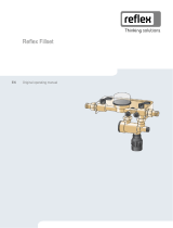
• Fillset for make-up with water.
– Fillset with integrated backflow preventer, water meter, dirt trap, and locking mechanisms for the "WC" make-up line.
• Fillset Impulse with FQIRA+ contact water meter for make-up with water.
– If the Fillset Impulse with FQIRA+ contact water meter is installed in the make-up line, you can regulate the entire make-up
quantity and the soft water capacity of Fillsoft softening systems. The operational reliability of the device is assured and
prevents the automatic make-up during major water loss or small leaks.
• Fillsoft for softening the make-up water from the public water network.
– Fillsoft is installed between Fillset and the device. The device controller evaluates the make-up quantities and signals a
required replacement of the softening cartridges.
• Enhancements for the device controller.
• Use the RS-485 interface to retrieve various data from the controller and to communicate with control centres or other
devices.,see chapter 6.5.2.1 "Connecting the RS-485 interface" on page 28 . You need the following items for the
communication of the RS-485 interface with control centres or other devices:
– Bus modules for the communication with control centres
– Lonworks Digital
– Lonworks
– Profibus-DP
– Ethernet
– I/O module for standard communication
• Reflexomat for system with pressure-maintaining stations.
– The Reflexomat and device combination is preferred. Despite the degassed network, Reflexomat assured an extremely elastic
operation at constant pressure. Make-up is executed depending on the water level measured with the "LIS" level sensor of the
Reflexomat in the expansion tank of the pressure maintaining station. For a make-up request, the Reflexomat controller
activates a 230 V signal to the device controller.
• Gas discharge measurement for an optimised degassing operation.
Notice!
Separate installation, operation, and maintenance instructions are supplied with the accessories and optional equipm
ent.

Technical data
14
— English Vacuum spray degassing — 06.07.2016 - Rev. B
5
Technical data
Note!
The following values apply for all systems:
–
Permissible flow temperature:
–
Permissible operating temperature makeup
degassing:
–
Permissible ambient temperature:
–
Permissible operating gauge pressure:
–
Maximum inlet pressure for makeup:
–
Makeup capacity:
–
Separation level, dissolved gases:
–
Separation level, free gases:
–
Degree of protection:
120 °C
0 °C – 30 °C
0 °C – 45 °C
8 bar
6 bar
0.05 m³/h
≤ 90 %
100 %
IP 54
5.1
Electrical system
Type
Power output
(kW)
Power supply
(V / Hz)
Fusing
(A)
Number of RS-
485 interfaces
I/O module
Electrical voltage
control unit
(V, A)
Noise level
(dB)
30 0.47 230 / 50 10 1 No 230, 4 55
30 GL 0.47 230 / 50 10 1 No 230, 4 55
5.2
Dimensions and connections
Type
Weight
(kg)
Height
(mm)
Width
(mm)
Depth
(mm)
Degassing
device
connection
Degassing
system
connection
Make-up
connection
30 13.5 660 545 290 IG ½ " IG ½ " IG ½ "
30 GL 13.5 660 545 290 IG ½ " IG ½ " IG ½ "
5.3
Operation
Type
System volume
(100% water)
(m³)
System volume
(50% water)
(m³)
Working
pressure
(bar)
Permissible operating
gauge pressure
(bar)
Setpoint overflow
valve
(bar)
Operating
temperature
(°C)
30 1 – 0.5 – 3 8 – >0 – 70
30 GL – 2.5 0.5 – 3 8 – >0 – 70

Technical data
Vacuum spray degassing — 06.07.2016 - Rev. B English —
15
Approximate values for the maximal "Va" system volume to be degassed under extreme conditions during commissioning at a nitrogen
reduction from 18 mg/l to 10 mg/l.
1 Continuous degassing "t" [h] 2 System volume "Va" [m3]

Installation
16
— English Vacuum spray degassing — 06.07.2016 - Rev. B
6
Installation
DANGER
Risk of serious injury or death due to electric shock.
If live parts are touched, there is risk of life-threatening injuries.
• Ensure that the system is voltage-free before installing the device.
• Ensure that the system is secured and cannot be reactivated by other persons.
• Ensure that installation work for the electric connection of the device is carried out by an electrician, and in compliance with
electrical engineering regulations.
CAUTION
Risk of injury due to pressurised liquid
If installation, removal or maintenance work is not carried out correctly, there is a risk of burns and other injuries at the connection
points, if pressurised hot water or hot steam suddenly escapes.
• Ensure proper installation, removal or maintenance work.
• Ensure that the system is de-pressurised before performing installation, removal or maintenance work at the connection points.
CAUTION
Risk of burns on hot surfaces
Hot surfaces in heating systems can cause burns to the skin.
• Wear protective gloves.
• Please place appropriate warning signs in the vicinity of the device.
CAUTION
Risk of injury due to falls or bumps
Bruising from falls or bumps on system components during installation.
• Wear personal protective equipment (helmet, protective clothing, gloves, safety boots).
Note!
Confirm that installation and start
-up have been carried out correctly using the installation, start-up and maintenance
certificate. This action is a prerequisite for the making of warranty claims.
–
Have the Reflex Customer Service carry out commissioning and the annual maintenance.

Installation
Vacuum spray degassing — 06.07.2016 - Rev. B English —
17
6.1
Installation conditions
6.1.1
Incoming inspection
Prior to shipping, this device was carefully inspected and packed. Damages during transport cannot be excluded.
Proceed as follows:
1. Upon receipt of the goods, check the shipment for
• completeness and
• possible transport damage.
2. Document any damage.
3. Contact the forwarding agent to register your complaint.
6.2
Preparatory work
Condition of the delivered device:
• Check all screw connections of the device for tight seating. Tighten the screws as necessary.
Preparing the connection of the device to the plant system:
• Barrier-free access to the plant system.
• Level and solid placement surface for the device.
• Frost-free, well-ventilated room.
– Room temperature > 0 - 45 °C.
• Drain for drain water.
• Filling connection.
– DN 15 according to DIN 1988 T 4.
• Electric connection.
– 230 V~, 50 Hz, 16 A with upstream ELCB (tripping current: 0.03 A).

Installation
18
— English Vacuum spray degassing — 06.07.2016 - Rev. B
6.3
Execution
CAUTION
Risk of injury due to tipping over of the device
Risk of bruising or crushing caused by tipping over of the device
• Ensure sufficient stability of the device.
• Weigh down the bearing surface of the device's transport unit with suitable means.
Note!
The screw connections at the device may loosen when the device is moved to another location.
–
Prior to using the device check the screw connections for proper seating and sealing.
Note!
Avoid leaks at the connections.
–
When connecting the device to the facility system, ensure that the connections for degassing and make-up are not
twisted.
Proceed as follows:
• Connect the device at the return flow side of the plant system.
– In this manner, you ensure that the device is operated within the permissible pressure and temperature ranges.
• In the case of a plant system with return flow admixture or a hydraulic switching point, connect the device upstream of the
switching point.
– In this manner, you ensure the water degassing in the 'V' main volume flow at temperatures ≤ 70 °C.
CAUTION
– damage due to improper connection! Bear in mind that the device may be subject to additional stresses through the
connection of piping or hose connections to the plant system. Ensure that all connections to the plant system are free from stresses. If
necessary, provide support structures for the pipes.
CAUTION
– Property damage caused by leaks! Leaks in the connection pipes to the device can cause material damage to the plant
system. Use only connection pipes with appropriate resistance against the plant system temperature.
The device is pre-wired and must be adapted for the local system conditions.
Proceed as follows:
1. Complete the water side connections from the device to the plant system.
2. Complete the electric connection as shown in the terminal plan, see chapter 6.5 "Electrical connection" on page 25 .
Note!
During connection, ensure the operability of the valves and the inlet options for the connecting lines.

Installation
Vacuum spray degassing — 06.07.2016 - Rev. B English —
19
6.3.1
Fitting the add-on components
Install the ball valves at the device.
1
. Attach the ball valve for the "WC" make-up connection.
– If you don't connect the automatic make-up, close the
"WC" connection with a G ½ " blind plug.
2
. Attach the ball valve with the "ST" dirt trap at the "DC" inlet
of the degassing.
3
. Attach the ball valve at the "DC" outlet of the degassing.
6.3.2
Wall mounting
Use the bores provided at the housing rear to attach the device
at the wall. Select the attachment means according to the wall
properties and the "G" weight of the device.

Installation
20
— English Vacuum spray degassing — 06.07.2016 - Rev. B
6.3.3
Hydraulic connection
6.3.3.1
Degassing line to the system
Installation detail of the "DC" degassing line
Install the 'DC' degassing pipes as shown below:
Proceed as follows:
• Prevent an overload of the "ST" dirt trap in the device caused by coarse dirt.
• Install the "DC" gas-rich degassing line upstream of the gas-poor degassing line when viewed in system flow direction.
• Preferably install at the return flow side of the plant system.
– The water temperature must be in the range of 0 °C to 70 °C to ensure sufficient degassing capacity.
/