Page is loading ...

Figure 2. Model T31832 Inventory.
Figure 1. Model T31832 Workbench Stand.
*Shown with optional T1254 Beech Workbench Top
For questions or help with this product contact Tech Support at (570) 546-9663 or techsupport@grizzly.com
MODEL T31832
96" X 25"
WORKBENCH STAND
INSTRUCTIONS
Introduction
This workbench stand is designed to be used
with solid wood workbench tops, and is ideal for
close-in detail work, such as soldering, assembly,
gunsmithing, etc. Features all-steel frame con-
struction and re-inforced corners.
COPYRIGHT © FEBRUARY, 2020 BY GRIZZLY INDUSTRIAL, INC.
NO PORTION OF THIS MANUAL MAY BE REPRODUCED IN ANY SHAPE
OR FORM WITHOUT THE WRITTEN APPROVAL OF GRIZZLY INDUSTRIAL, INC.
(FOR MODELS MFD. SINCE 01/20) #KS20960 PRINTED IN TAIWAN
V1.02.20
Specifications
• Stand (Length x Width) .................... 91" x 20"
• Height .................................................... 35
1
⁄2"
• Maximum Weight Capacity .............2500 lbs.
• Approximate Assembly Time ........45 Minutes
Needed for Assembly
• Additional Person ........................................ 1
Inventory (Figure 2)
Description Qty
A. Center Frame .............................................. 1
B.
End Frames ................................................. 2
C.
Upper Supports ........................................... 4
D.
Lower Supports ........................................... 2
E.
Rubber Feet M10-1.5 x 35 ........................... 6
F.
Hardware Bag
— Support Brace .......................................... 1
— External Corner Braces ........................... 6
— Internal Corner Braces ............................12
—Button Hd Cap Screws M8-1.25 x 55
.... 38
— Flat Washers 8mm ................................. 68
— Lock Nuts M8-1.25 ................................. 30
—Wrench 13/14mm Open-Ends
.................. 1
— Hex Wrench 5mm .................................... 1
G.
Steel Bars
5
⁄8" x 11
3
⁄4" .................................12
B
C
D
E
F
A
G

Figure 3. End frame and center frame attached
to workbench top.
x 2
x 1
End Frame
Center
Frame
End of
Workbench Top
Figure 4. Upper support attached to workbench.
x 1
Upper
Support
Side of
Workbench
Top
Figure 5. End frame and upper support secured
together with corner braces.
x 3
End Frame
Upper
Support
External
Corner Brace
Internal
Corner
Brace
-2-
Model T31832 (Mfd. Since 01/20)
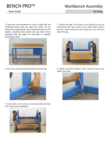
Assembly
To assemble the workbench stand:
1.
Lay workbench top upside-down on a pro-
tected surface, such as cardboard or a
blanket.
2.
Attach both end frames and center frame to
workbench top with (4) M8-1.25 x 55 button
head cap screw and (4) 8mm flat washer (see
Figure 3). DO NOT fully tighten fasteners at
this time.
3.
Attach each upper support to work-
bench top with (1) M8-1.25 x 55 button
head cap screw and (1) 8mm flat wash-
er (see Figure 4). DO NOT fully tighten
fasteners at this time.
4.
Secure end frames and upper supports with
(4) external corner braces and (4) internal
corner braces, using (3) M8-1.25 x 55 button
head cap screws, (6) 8mm flat washers, and
(3) M8-1.25 lock nuts for each corner (see
Figure 5). DO NOT fully tighten fasteners at
this time.
5.
Secure center frame and upper supports
with (1) support brace and (4) internal corner
braces, using (8) M8-1.25 x 55 button head
cap screws, (16) 8mm flat washers, and (6)
M8-1.25 lock nuts (see Figure 6). DO NOT
fully tighten fasteners at this time.
The Model T31832 Workbench Stand can be used
with many different types of solid wood work-
bench tops, but it is best paired with the Grizzly
Model T1254 Beech Workbench Top, which has
threaded mounting holes located specifically for
mounting the T31832 frame.
— If you are using a Grizzly Model T1254
Beech Workbench Top, proceed to Step
1.
— If you choose to use your own workbench
top, complete Steps 4–7 BEFORE per-
forming Steps 1–3. Proceed to Step 8
once all previous steps are completed.

Figure 6. Center frame and upper supports
secured together with braces.
x 8
Upper Frame
Support
Center
Frame
Support
Brace
Internal
Corner
Brace
Figure 7. End frame, center frame, and lower
supports secured together with corner braces.
Figure 8. Rubber foot threaded into bottom of
end frame.
End Frame
Rubber
Foot
Figure 9. Steel bars inserted into holes in frame
for shelving/racking.
Center
Frame
End Frame
Steel Bars
Upper Frame
Support
x 6
End Frame
Center Frame
x 4
Internal
Corner
Brace
Internal
Corner
Brace
External
Corner
Brace
Model T31832 (Mfd. Since 01/20)
-3-
7. Thread rubber feet into bottoms of frames
(see Figure 8).
8.
Turn workbench upright and make sure it is
centered over end frames and supports (not
leaning to one side or the other), then fully
tighten all fasteners.
9.
Adjust feet as necessary to level table. Verify
workbench sits firmly on ground and does not
wobble.
Note: Lay a level across the workbench
top from side-to-side and end-to-end when
adjusting feet.
10.
Insert steel bars through end support frames
as desired (see Figure 9).
Note: Each end frame has several
holes, which allows for numerous shelving
and racking configurations.
6.
Secure end frames, center frame, and lower
supports with (2) external corner braces and
(4) internal corner braces, using (10) M8-1.25
x 55 button head cap screws, (20) 8mm flat
washers, and (10) M8-1.25 lock nuts (see
Figure 7). DO NOT fully tighten fasteners at
this time.

Please Note: We do our best to stock replacement parts whenever possible, but we cannot guarantee that all parts shown here
are available for purchase. Call (800) 523-4777 or visit our online parts store at www.grizzly.com to check for availability.
REF PART # DESCRIPTION REF PART # DESCRIPTION
2 PT31832002 END FRAME 9 PT31832009 BUTTON HD CAP SCR M8-1.25 X 55
3 PT31832003 CENTER FRAME 10 PT31832010 FLAT WASHER 8MM
4 PT31832004 UPPER SUPPORT 11 PT31832011 LOCK NUT M8-1.25
5 PT31832005 LOWER SUPPORT 12 PT31832012 RUBBER FOOT M10-1.5 X 35
6 PT31832006 SUPPORT BRACE 13 PT31832013 STEEL BAR 5/8 X 11-3/4
7 PT31832007 EXTERNAL CORNER BRACE 14 PT31832014 WRENCH 13/14MM OPEN-ENDS
8 PT31832008 INTERNAL CORNER BRACE 15 PT31832015 HEX WRENCH 5MM
9
10
7
9
10
9
10
10
11
8
11
10
7
10
11
4
9
10
13
2
12
10
11
8
5
14
15
3
12
8
13
11
10
9
10
5
13
2
12
9
10
11
10
9
10
7
8
11
10
4
8
9
10
9
10
11
10
6
6
-4-
Model T31832 (Mfd. Since 01/20)
BUY PARTS ONLINE AT GRIZZLY.COM!
Scan QR code to visit our Parts Store.
Parts Breakdown
/