8
www.dimplex.com
SECTION D: ALTERNATE CONTROL OPTIONS
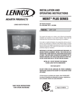
240V MAIN POWER WALL SWITCH
!
NOTE: This option should not be used with the remote control kit.
!
NOTE: Before installing the unit have the following wires installed:
1. A 3 conductor wire with ground (4 wires total) from the power supply panel to the main switch wall box.
2. A 3 conductor wire with ground (4 wires total) from the main switch wall box to the junction box on the unit.
!
NOTE: Use a double pole, single throw (On/Off) wall switch that is rated for a minimum of 15 amps.
1. Locate the voltage selector switch inside the exhaust panel on the top right hand corner of the unit. Ensure that the
switch is in the 240V position. (230 is printed on switch)
2. Loosen the screw securing the junction box cover and remove the cover.
3. Remove the knockouts (if necessary) or use the provided cable clamp.
4. Pull out the four wires marked L1, L2, N, and G. (black, red, white and green)
5. Connect the L1 (black) wire from the unit to the L1 (black) wire from the main power wall switch by using a wire connector
(not supplied).
6. Connect other end of L1 (black) wire from the main power wall switch to the L1 terminal of the main power wall switch.
7. Connect the L2 (red) wire from the unit to the L2 (red) wire from the main power wall switch by using a wire connector
(not supplied).
8. Connect the other end of the L2 (red) wire from the main power wall switch to the L2 terminal of the main power wall
switch.
9. Connect the N (white) wire from the unit to the N
(white) wire from the main power wall switch by
using a wire connector (not supplied).
10. Connect the G (green) wire from the unit to the G
(green) wire from the main power wall switch by
using a wire connector (not supplied).
11. Connect the L1 wire from the power supply to the
L1 terminal of the main power wall switch.
12. Connect the L2 (black) wire from the power
supply to the L2 terminal of the main power wall
switch.
13. Connect the N (white) wire from the power supply
to the remaining N (white) wire from the unit by
using a wire connector.
14. Secure the 2 remaining G (green) wires with a
ground screw in the main switch wall box.
15. Ensure that all connections are tight.
16. Insert all the wiring of the main power wall switch
into the main switch wall box.
17. Insert all the wiring back into the unit and secure
with a cable clamp.
UNIT AND SUPPLY
NEUTRAL FROM
G FROM UNIT
POWER SUPPLY
G FROM
L1 FROM
POWER SUPPLY
POWER SUPPLY
L2 FROM
L1 FROM UNIT
G
L1
L2 FROM UNIT
N
L2
3 CONDUCTOR WIRE
FROM POWER SUPPLY
3 CONDUCTOR WIRE
FROM MAIN SWITCH
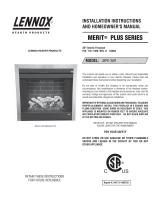
UNIT AND SUPPLY
NEUTRAL FROM
L2 FROM UNIT
L1 FROM UNIT
L2 FROM
POWER SUPPLY
POWER SUPPLY
L1 FROM
G FROM
POWER SUPPLY
G FROM UNIT
G
L2
N
L1
240 V
POWER
SUPPLY
(BREAKER
PANEL)
WALL
SWITCH