Hanover TRADDN5PCSW2BN-RED Installation guide

Type
Installation guide

This manual is also suitable for

HanoverOutdoorFurniture
IMPORTANT
Ifyouhaveanyproblemswiththisproduct(missingordamagedparts,assemblyissues,etc.),
PLEASEDONOTRETURNTOTHERETAILER/STORE
fromwhereyoupurchasedtheproduct.
PleasecallourTollFreeCustomerServiceHotlineat:
18004163511
Between9:00AMand5:00PMEasternTime,MondaythroughFriday
Orvisitourwebsiteat:
www.hanoverproducts.com
Toexpediteanyfuturewarrantyclaims,pleaseretaintheInstructionSheet,Warranty
Cardandreceiptforfutureuse.
For additionalonlinesupportonassembly,troubleshootingandcare&maintenanceofyouroutdoor
furniture,pleasevisitourwebsiteat:www.hanoverproducts.com.
6/1/2015(a)
Page 4
ASSEMBLY INSTRUCTIONS
1
2
Important: We recommend 2 people work together to assemble the chair.
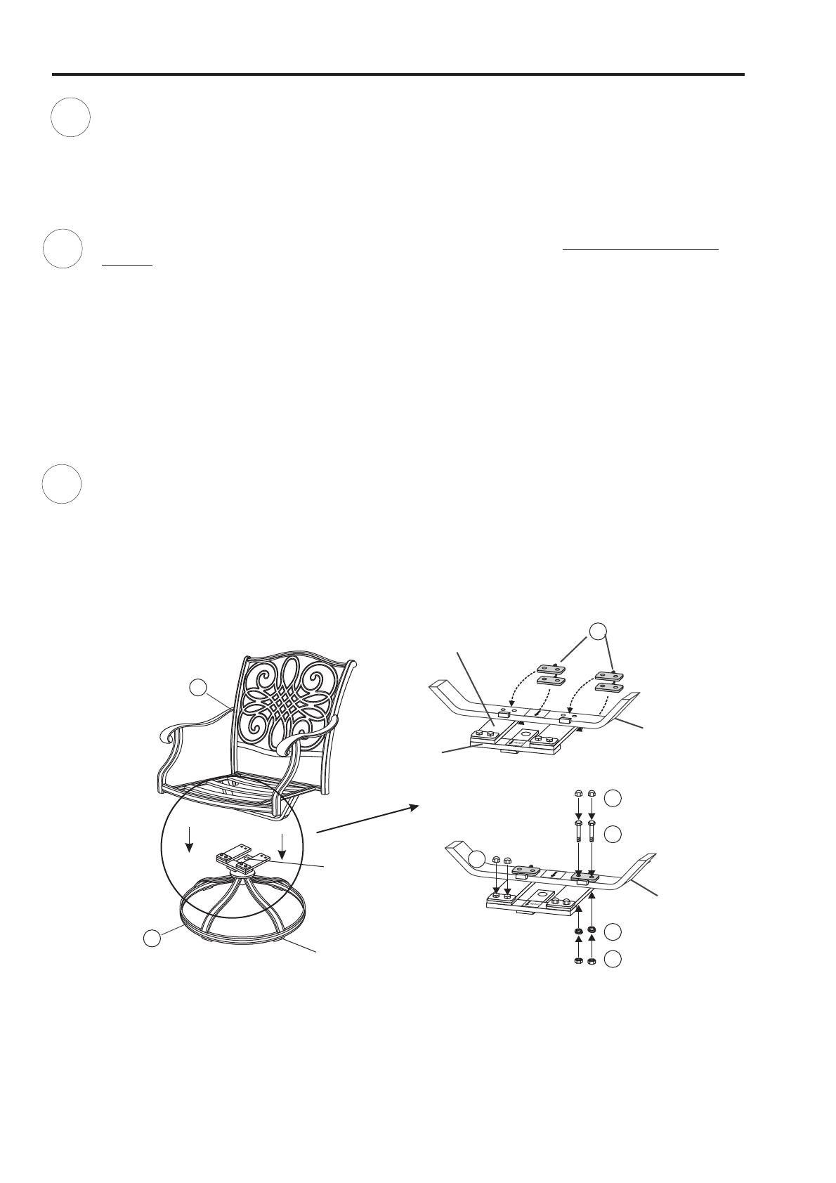
If chair frame has been properly positioned
on the rocker assembly, all arrows on the "U" bar and rocker assembly will be pointing in the same direction.
Note the arrow labels on the "U"
bar and the rocker assembly. Also note the horseshoe shape of the rocker plate. Point the open end of the horseshoe
away from you. The arrows on the rocker assembly should be pointing towards you. Set the chair frame on the
rocker assembly with front of the seat facing you and the arrows on the "U" bar pointing towards you as shown in
. This is very important for a safe, balanced rocking motion.Figure 1
Critical Step: The "U" metal plates must be installed in the proper location.
Hand tighten nuts 3-4 revolutions only.
CAUTION: Failure to place "U" metal plates under the rocker plates and above the"U" bar exactly as shown
in diagram will cause the bolt heads and nuts to damage the structure of the rocker plates and the "U" bar.
Damage due to over tightening of bolts or improper assembly could cause injury and may void your warranty.
Insert the "U" metal plate, so that the "U" bar and rocker plate are between both sides of the "U" metal
plate. Make sure that the holes in the "U" metal plate are completely aligned with the holes in the "U" bar as shown
in . Guide the bolts through the holes on the top side of the "U" metal plate, through the holes in the "U"
bar portion of the chair, through the holes in the rocker plate and then, most importantly, through the holes in the
bottom side of the "U" metal plate. It is very important that the holes in the bottom portion of the "U" metal plate
be placed directly beneath the holes in the rocker plate. Add a spring washer and a nut to each bolt as shown in
. Repeat the same procedure on the other side.
Read this step and carefully
examine.
Figure 2
Figure 2
3
Tighten all nuts and bolts with the hex wrenches provided. Remove arrow labels
from "U" bar and rocker assembly. Cover bolts with bolt covers.
Bolts must be FULLY tightened.
FOOT CAP
B
COVER
A
Figure 1
Figure 2
ROCKER PLATE
E
G
C
D
F
"U" BAR
ROCKER
ASSEMBLY
"U" BAR
G
Page 5
*NOTE:PARTSSHOWNONPARTSLISTARENOTTOSCALE
PARTS IDENTIFICATION LIST
HEX WRENCH-1
HW0008
1
HEX WRENCH-2
HW0007
1
G0141
FOOT CAP
FACTORY ASSEMBLY
FC0031
AAF06001
BOLT COVER
HW0028
8
QTY
SWIVEL BASE &
ROCKER
ASSEMBLY
5/16" X 40 MM
BOLT
HW0003
5/16" NUT
HW0015
"U" METAL
PLATE
CHAIR FRAME
PARTS LIST
DESCRIPTION ORDER PART #
2
4
4
4
1
1
HW0295
HW0618
A
B
C
D
E
F
G
H
I
ROCKER PLATE
FACTORY ASSEMBLY
Ø8.0 X 2.3 MM
SPRING WASHER
AR19742
AR19743
Page 4
ASSEMBLY INSTRUCTIONS
1
2
C
Attach a leg connector bar to the middle leg by using the bolts and washers as shown in .
Guide the bolts through the holes in the leg connector bar, into the pre-drilled holes in the middle
leg. Repeat for the other leg connector bar.
F1
Hand tighten only 2-3 turns.
igure
D
Attach a side leg to the leg connector bar by using the bolts and washers as shown in .
Guide the bolts through the holes in the leg connector bar, into the pre-drilled holes in the side leg.
Repeat for the other side leg.
F2
Hand tighten only 2-3 turns.
igure
E
F
G
B
3
Attach the assembled base to the seat frame by using the bolts and washers as shown in . Guide
the bolts through the holes in the side legs and middle leg, into the pre-drilled holes in the seat frame.
F3
Hand
tighten only 2-3 turns.
igure
G
E
F
G
E
F
4
After making any necessary adjustments to the alignment of the , use the hex bolt driver to tighten
all bolts. Repeat until all bolts are tight. Over tightening may strip bolts. Cover
all bolts with covers.
Do not over tighten.
ottoman
F1igure
Figure 2
Figure 3
Page 5
* NOTE: PARTS SHOWN ON PARTS LIST ARE NOT TO SCALE
PARTS IDENTIFICATION LIST
QTY
PARTS LIST DESCRIPTION ORDER PART #
A
B
C
D
E
F
G
H
AAL08045
1/4" X 20 MM BOLT
HW0036
14
14
Ø6.5 X 1.0 MM
WASHER
HW0004
FOOT CAP
FACTORY ASSEMBLY
FC0030
SEAT FRAME
2
1
SIDE LEG
1
HEX BOLT DRIVER
HW0006
HW0105
BOLT COVER
14
1
MIDDLE LEG
LEG CONNECTOR
BAR
2
AA0729
AA0730
AA0731
AA0732
Page 4
ASSEMBLY INSTRUCTIONS
1
2
Attach a leg to the leg connector bracket by carefully guiding the bolts already in place on the table legs (each leg
has two bolts) through the holes in the leg connector bracket. Add a washer and a nut to the end of each bolt
. Repeat on the other three legs.Fig. Hand tighten only. Do not tighten completely.
as
shown in 2
3
After making any necessary adjustments to the alignment of the table legs and the leg connector bracket, use the
hex bolt driver and hex wrench to tighten all nuts and bolts. each bolt and nutmust be tightened a few rev-
olutions at a time. In order to apply equal pressure to all bolt joints, we recommend working in a cross corner (X
fashion). Repeat until all bolts are tight. . Over tightening may strip bolts. Cover all nuts
and bolts with covers.
Note:
Do not over tighten
Place the table top upside down on a flat, non-abrasive surface. Attach a table leg to the table top by using the bolts
and washers as shown in . Guide bolts through holes in the table legs and into the pre-drilled holes in the table
top. Repeat for the other three legs.Hand tighten 2-3 turns only.
Fig.1
Fig.1
Fig.2
FOOT CAP
A
E
G
H
B
F
E
D
C
Page 5
*NOTE:PARTSSHOWNONPARTSLISTARENOTTOSCALE
PARTS IDENTIFICATION LIST
PARTS LIST DESCRIPTION ORDER PART #
QTY
1
1
A
B
C
D
E
F
G
H
I
J
16
1
BOLT COVER
HEX BOLT DRIVER
1/4" X 18 MM BOLT
TABLE LEG
LEG CONNECTOR
BRACKET
TABLE TOP
FC0069
HW0105
HW0004
HW0035
HW0014
HW0027
HW0009
HW0006
FOOT CAP
FACTORY ASSEMBLY
4
8
8
NUT COVER
8
HEX WRENCH
1
1/4" NUT
8
Ø6.5 X 1.0 MM
WASHER
UMBRELLA HOLE
PROTECTIVE
RING (SET)
FACTORY ASSEMBLY
G0235 & G0236
UMBRELLA POLE
STOPPER & NUT
FACTORY ASSEMBLY
G0091
& HW0448
AT71868
AT71869
AT71870
  • Page 1 1
  • Page 2 2
  • Page 3 3
  • Page 4 4
  • Page 5 5
  • Page 6 6
  • Page 7 7

Hanover TRADDN5PCSW2BN-RED Installation guide

Type
Installation guide
This manual is also suitable for

Ask a question and I''ll find the answer in the document

Finding information in a document is now easier with AI