Speakman SE-362 Installation guide

Type
Installation guide

Speakman SE-362, a thermostatic mixing valve, prevents scalding by automatically adjusting the blend of hot and cold water, delivering a consistent and safe water temperature. Its temperature range is from 65 to 95 degrees Fahrenheit, and it requires a minimum temperature differential of 20 degrees Fahrenheit from the valve's set point.

Speakman SE-362, a thermostatic mixing valve, prevents scalding by automatically adjusting the blend of hot and cold water, delivering a consistent and safe water temperature. Its temperature range is from 65 to 95 degrees Fahrenheit, and it requires a minimum temperature differential of 20 degrees Fahrenheit from the valve's set point.

215-1726 Rev. A; EN 11-09-005
© 2011 Speakman Company
Page 1 of 22 9-6-2011
SE-362
Speakman/SE-362
Thermostatic Mixing Valve
with Optional Cabinet
Robinet
thermostatique
mélangeur
avec cabinet facultatif
Válvula mezcladora termostática
con armario opcional
Table of Contents
Supplies Required ..................................................... 2
Optional Equipment Installation ................................ 2
Dimensions ............................................................... 3
Installation Instructions ............................................. 4
Troubleshooting ......................................................... 7
Sommaire
Fournitures requises ................................................. 9
Installation de l’équipement optionnel ....................... 9
Dimensions ............................................................. 10
Instructions relatives à l’installation ......................... 11
Dépannage ............................................................. 13
Tabla de contenidos
Materiales necesarios ............................................. 16
Instalaciones de equipos opcionales ...................... 16
Dimensiones ........................................................... 17
Instrucciones de instalación .................................... 18
Solución de problemas ........................................... 20
Installation
Inlet Connections: 3/4" NPT
Outlet Connection: 1" NPT
Temperature Range: 65˚95˚ F
Maximum Pressure: 125 PSI
Inlet Temperature Hot: 120˚180˚ F
Inlet Temperature Cold: 33˚80˚ F
Minimum Temperature Differential
(from valve set point): 20˚ F
Inlet Connections: 3/4» NPT
Outlet Connection: 1» NPT
Temperature Range: 65˚95˚ F
Maximum Pressure: 125 PSI
Inlet Temperature Hot: 120˚180˚ F
Inlet Temperature Cold: 33˚80˚ F
Minimum Temperature Differential
(from valve set point): 20˚ F
Inlet Connections: 3/4» NPT
Outlet Connection: 1» NPT
Temperature Range: 65˚95˚ F
Maximum Pressure: 125 PSI
Inlet Temperature Hot: 120˚180˚ F
Inlet Temperature Cold: 33˚80˚ F
Minimum Temperature Differential
(from valve set point): 20˚ F
French Spanish
P.O. Box 191, Wilmington, DE 19899-0191 USA
Phone: 1.800.537.2107 Fax: 1.800.977.2747
www.speakmancompany.com
Shown with
Optional #S86-068
Cabinet with
#S45-1773 Piping
and Ball Valves
Speakman/SE-362 Installation
2 9-6-2011 Speakman Company • 215-1726 Rev. A; EN 11-09-005
Supplies recommended for installation
• Lockableshut-offontheoutletiftemperedwaterissuppliedtooneormoreemergencyfixtures
• Lockableshut-offontheinlets/supplies
• (6)3/8"wallanchorsandfastenersforsurface-mountedcabinet
• (4)1/4"fasteners(andwallanchors,ifnecessary)forrecess-mountedcabinet
• Unionsonallconnectionstofacilitateremovalofvalve
Tools required for temperature adjustment
• 5/32"Allenwrench
• Bladescrewdriver
1
Install Optional Cabinet (If not installing cabinet, skip to Step 2)
Recessed Cabinet:
1. Rough-in wall opening 24-1/2" W x 24-1/2".
2. Insert the cabinet and secure to wall with four 1/4" fasteners
properly anchored (supplied by installer.)
3. Install two anchors and screws through the valve bracket in
back of the cabinet into a secure brace (supplied by installer) or
into wall. This will support the valve.
4. Install the valve nipples and one-half of the union ball valve
using pipe sealant or teflon tape. Install the other half of the
union ball valve onto inlet and outlet pipe.
5. Insert the valve into the bracket in the cabinet (right side goes
in first). Continue with the valve installation procedure.
6. Position the wall flange tight to the wall and caulk in place.
Surface-Mounted Cabinet:
1. Measure and mark the cabinet mounting hole locations
at the dimensions shown on next page. Install six 3/8" wall
anchors (supplied by installer).
2. Position the cabinet onto the wall and secure into place
with six 3/8" wall fasteners (supplied by installer).
3. Install the valve nipples and one-half of the union ball
valve using pipe sealant or teflon tape. Then install the
other half of the union ball valve onto the inlet and outlet
piping.
4. Insert the valve into the bracket in the cabinet (right
side of the valve goes in first). Continue with the valve
installation procedure.
IMPORTANT!
Read this entire installation manual to ensure proper installation. When
finished with the installation, file this manual with the owner or maintenance
department. Compliance and conformity to local codes and ordinances is
the responsibility of the installer.
Separate parts from packaging and make sure all parts are accounted for
before discarding packaging material. If any parts are missing, do not begin
installation until you obtain the missing parts.
Make sure that all water supply lines have been flushed and then completely
turned off before beginning installation. Debris in supply lines can cause
valves to malfunction.
Installation
THIS
SIDE
UP
Packing List
Installation Speakman/SE-362
Speakman Company • 215-1726 Rev. A; EN 11-09-005 9-6-2011 3
Mounting Hole Locations
7-1/2"
(191)
8-7/16"
(214)
20"
(508)
20"
(508)
6-1/4"
(159)
2"
(51)
2"
(51)
0.47 Dia. Holes
(6) Places
(mm)
22-3/4" (578)
Door
10-1/2"
(267)
8-1/2"
(216)
7"
(178)
26"
(660)
24"
(610)
Nipple
Union Ball
Valve
2" (51)
2" (51)
2" (51)
2" (51)
1" NPT
Outlet
0.28" Dia. Holes
(4) each side,
(8) Total
6-1/2"
(165)
2"
(51)
3/4" NPT
Inlets
5"
(127)
14"
(356)
24"
(610)
Wall
Flange
22-3/4"
(578)
Door
26"
(660)
Bottom View
22-3/4" (578)
Door
10-1/2"
(267)
8-1/2"
(216)
7"
(178)
24"
(610)
Nipple
Union Ball
Valve
2" (51)
2" (51)
2" (51)
1" NPT
Outlet
6-1/2"
(165)
3/4" NPT
Inlets
22-3/4"
(356)
Door
24"
(610)
Side View
Front View
Optional Recessed Cabinet
Optional Surface-Mounted Cabinet
Wall Opening:
24-1/2" W x 24-1/2" H
Speakman/SE-362 Installation
4 9-6-2011 Speakman Company • 215-1726 Rev. A; EN 11-09-005
2
Connect Supply Lines and Install Thermometer
3
Adjust Temperature with Water Running
When the check valves are in the
open (opera ting) position, the cover
screw for the stop/check stem will
be flush with the valve cap.
Check for leaks by pressurizing
unit SLOWLY.
Install Thermometer using pipe
sealant or teflon tape.
Check the temperature when approximately 10 GPM
water flow is reached (equivalent to two face washes)
Slotted Cover
Screw
Stop/Check
Cover Screw
Check
Stop Nut
Water Recirculation
Plug
Thermometer
Tempered Water
(to Fixture)
HOT
COLD
Slotted Cover
Screw
Temperature Set
Screw
C
H
4
Test Unit
Shut the hot water supply off by closing hot water inlet valve or supply check valve. While the hot water supply is turned off,
check to make sure the cold water continues to flow. If the cold water is flowing properly, reopen the hot water supply.
Shut the cold water supply off by closing the cold water inlet valve or supply check valve. While the cold water supply is off,
check to make sure that the hot water flow has shut down. If hot water is shut down, reopen cold water supply. Test unit
weekly for proper function and desired set temperature.
DO NOT SKIP THIS STEP!!!
This device must be checked for final temperature and adjusted as
necessary. The standard preset factory temperature setting is 85°F
(29°C). [the range of the valve is 65°F–95°F (18°C–35°C)]. Consult
proper medical and/or safety authorities for the optimum temperature
recommended for your particular application.
5/32" Allen Wrench
Installation Speakman/SE-362
Speakman Company • 215-1726 Rev. A; EN 11-09-005 9-6-2011 5
5
Optional Water Recirculation Setup
Check Valve
(Typ)
COLD
HOT
Heat Trap
28" Drop
Balancing Valve (Typ)
Water
Heater
Storage
Tank
Tempered Water Flow
Return Flow
Temperature Switch
Recirculated
Tempered
Water
Recirculating Pump
Cold
Water
Recirculating the water in the system provides constant regulation of the water temperature. Flush the supply lines thoroughly
after completing installation. Close off all fixtures and label them as not available for use durin g the recirculating process.
1. Turn off the recirculating pump and turn on the water supply at emergency fixture (a water flow rate of 10-15 GPM is required).
2.Letthewaterrunthroughthesystemuntilaconsistenttemperatureisobtained.Ifyoudonotobtaintherequiredtemperature,
refer to step #3 on previous page for temperature readjustment.
3. As soon as the water reaches the proper temperature, turn on the recirculating pump (make certain the proper system
temperature has been achieved before proceeding).
4. Check the water temperature at the return pump. If the temperature exceeds the appropriate level by 2°F, adjust the temperature
high-limit switch (this will turn off the pump). Wait until the return water temperature is 5°F below the appropriate level and adjust the
low-limit switch (this will turn the pump back on).
5. Open the balancing valve completely.
6. Turn off all fixtures and make sure there is no water running through the system (the cold inlet pipe should feel warm to the touch).
7.Letthesystemrunfor30minutesorlongerwithoutwater.If,afterthirtyminutes,thewatertemperatureincreases,youmay
readjust the temperature by slowly closing the balancing valve until the appropriate temperature is reached.
Alternate
Recirculation
(less than 5 GPM)
Speakman/SE-362 Installation
6 9-6-2011 Speakman Company • 215-1726 Rev. A; EN 11-09-005
Troubleshooting Thermostatic Mixing Valve
Problem Cause Solution
External leaks in the
system
Either the NPT joints or the o-rings have been
damaged.
Replace the NPT joints and/or o-rings where necessary. For
replacement of o-rings, contact your representative and ask for
O-Ring Seal Kit (S65-173).
No hot water flow (cold
water flow only)
The thermostat has failed and, subsequently, the
safety shut-off has engaged.
Inspect Thermostat:
1. Remove the top cap and pull out the push rod and thermostat.
2. Insert a 7/16" dia. rod into the thermostat bellows.
3. Mark the length of the thermostat bellows (at room temperature,
with 10 lb. of force, the bellows length should be approx. 1-3/16"—1-
1/2" ).
4. If the thermostat bellows length is not in the proper range, the
thermostat must be replaced (it cannot be repaired). Contact your
representative and ask for Thermostat Kit (S65-174).
Limitedwaterow The inlet shut-off valve may be partially closed
or there has been a significant decrease in water
pressure.
Dirt and debris have collected on the check
screen or seat, limiting the movement of the stop
and checks.
Clean Stop and check Valves:
Remove the stop and checks, clean the screen and seat and
reassemble the valve. Do not remove the seat. The components
may be scraped with a screwdriver to remove debris. A pair of
tweezers works well for pulling debris out from the seat. If the stop
and checks need to be replaced, contact your representative and
ask for Check/Stop Kit (S65-337).
Temperature fluctuation
or improper Temperature
The stop and check sections of the valve do not
move freely.
Clean Stop and Check Valves as described above.
Thermostat is slowly failing. Check Thermostat as described above, or replace.
Inlet supply line to the mixing valve is being
shared by other pieces of equipment that are
used only periodically, such as laundry appliances
or washdown stations. It may reduce the inlet
pressure to the mixing valve to less than 10 PSI.
The supply line size may not be large enough to
supply both the valve and the other appliances.
Enlarge the supply line size, reconfigure the supply line or regulate
the supply usage.
Recirculation is not balanced. Review recirculation set up on page 5.
Piston does not move freely and must be cleaned. See next page for piston disassembly and cleaning directions.
Before attempting to troubleshoot the valve or
disassemble the components, check for the following:
Stop/check valves are fully open (the slotted stem
must be flush with the stop/check cap) and that all
inlet and outlet shut-off valves are open
Hot and cold inlet pipes are connected properly,
and that there are no cross-connectio ns or leaking
stop/check valves
Water heater output is at least 15° F above the set
temperature.
Be sure to close the appropriate shut-off valves prior
to disassembly of the valve and reopen the valves
after inspection and repair is complete.
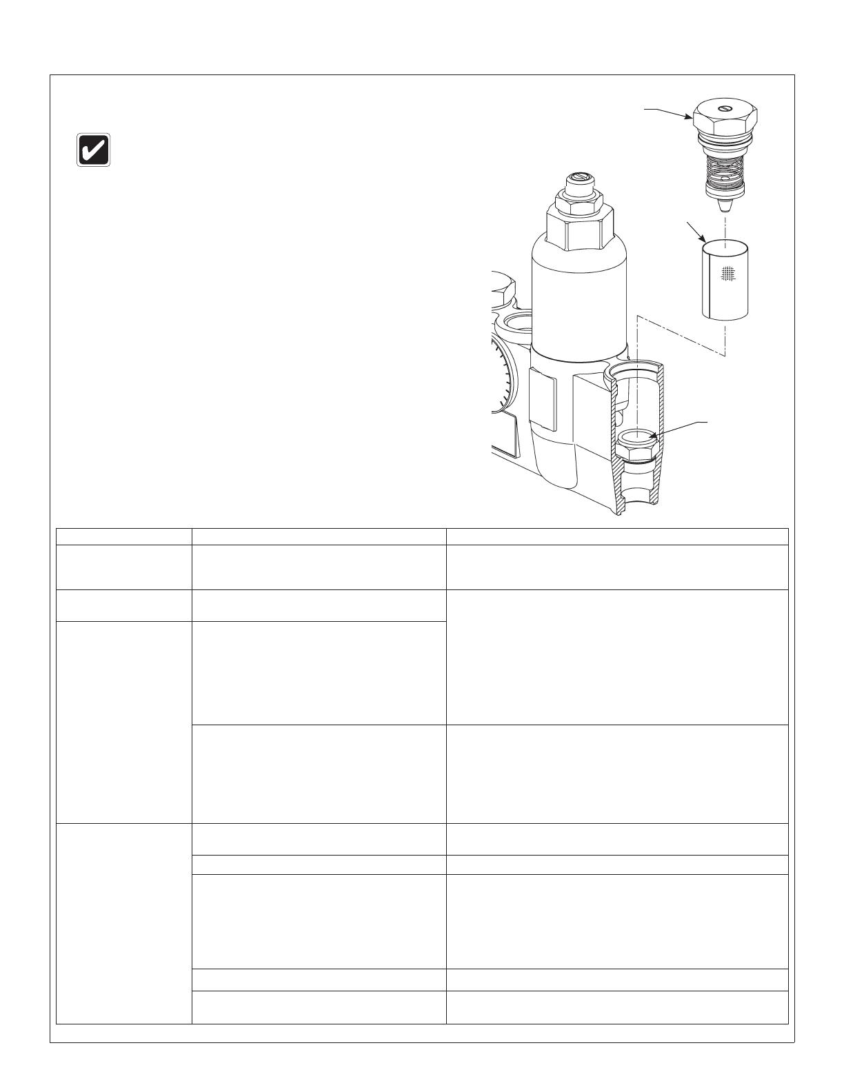
Stop/Check Valve
Valve Seat
Stop/Check
Strainer
Installation Speakman/SE-362
Speakman Company • 215-1726 Rev. A; EN 11-09-005 9-6-2011 7
C
If the rod travels less than1/2", the piston is not
moving freely within the liner and they must be
cleaned:
1. Remove the control section assembly, top cap
and thermostat.
2. Unthread the liner from the cap (it is glued
together; the o-rings must be removed and heat
should be applied to melt the glue and loosen
the liner).
3. Clean the piston and liner with any cleaner
suitable for brass and stainless steel (400-grit
sandpaper may be used to polish and hone the
piston and liner).
Troubleshooting: Piston Disassembly and Cleaning
To prevent injuries, use proper protective equipment for
eyes and skin when using a propane torch.
Thermostat
Pushrod
Top Cap
7/16"
Rod
Piston Overheat
Chamber
The second mark
should be 1/2"
higher on the rod
than the first mark.
B
Insert a 7/16" dia. rod into the valve and into the
piston overheat chamber. Mark the length of the
rod inside the valve. Push the rod until the piston
stops and mark the new length.
D
Push the mechanism up and down several times
to make sure the piston moves smoothly and
consistently. If it is not consistent, repeat Procedure
C until it moves freely, or replace. Contact your
representativeandaskforPiston/LinerKit(part
number S65-175).
A
Remove the valve’s top cap and pull out the
push rod and then the thermostat. You may use a
needle-nose pliers to remove the thermostat from
the valve body if desired.
Speakman/SE-362 Installation
8 9-6-2011 Speakman Company • 215-1726 Rev. A; EN 11-09-005
2
3
4
5
6
7
8
9
13
10
11
12
15
14
16
17
18
19
20
21
26
31
36
36
22
27
32
23
28
33
24
29
29
34
33
25
30
35
35
46
Parts Breakdown
25
Item Qty. Description
4 1 Washer
32 2 Seal
33 3 Washer
Washer/Seal Kit S65-310
Item Qty. Description
2 1 O-Ring
10 1 O-Ring
12 1 O-Ring
17 1 O-Ring
18 1 O-Ring
19 1 O-Ring
21 1 O-Ring
26 2 O-Ring
28 2 O-Ring
36 2 O-Ring
O-Ring Kit S65-173
Item Qty. Description
25 2 Cap
26 2 O-Ring
27 2 Stem
28 2 O-Ring
29 2 Strainer
30 1 Hot Supply
Spring
31 2 Holder
(for Seal)
32 2 Seal
33 2 Washer
34 2 Nut
35 2 Seat
36 2 O-Ring
46 1 Cold Supply
Spring (Blue)
Check/Stop Kit S65-337
Item Qty. Description
15 1 Thermostat
17 1 O-Ring
21 1 O-Ring
Thermostat Kit S65-174
Item Qty. Description
2 1 O-Ring
3 1 Liner
4 1 Washer
5 1 Screw
6 1 Spring
7 1 #10-24 Hex Nut
8 1 Spring
9 1 Retainer
10 1 O-Ring
11 1 Piston
12 1 O-Ring
13 1 Overheat Screw
14 1 Upper Seat
33 1 Washer
Piston & Liner Kit S65-175
Item Qty. Description
2 1 O-Ring
3 1 Liner
4 1 Washer
5 1 Screw
6 1 Spring
7 1 #10-24 Hex Nut
8 1 Spring
9 1 Retainer
10 1 O-Ring
11 1 Piston
12 1 O-Ring
13 1 Overheat Screw
14 1 Upper Seat
15 1 Thermostat
16 1 Pushrod
17 1 O-Ring
18 1 O-Ring
19 1 O-Ring
20 1 Mixing Valve Cap
21 1 O-Ring
22 1 Control Cap
23 1 Set Screw
24 1 Screw
33 1 Washer
Center Section Kit S65-304
Kit numbers for rough brass finish and
standard range thermostat.
Cold Supply Spring is
marked with blue paint. DO
NOT SWITCH WITH HOT
SUPPLY SPRING (30).
Brass Pipe (3/4" IPS)
Valve Body
Thermometer
  • Page 1 1
  • Page 2 2
  • Page 3 3
  • Page 4 4
  • Page 5 5
  • Page 6 6
  • Page 7 7
  • Page 8 8
  • Page 9 9
  • Page 10 10
  • Page 11 11
  • Page 12 12
  • Page 13 13
  • Page 14 14
  • Page 15 15
  • Page 16 16
  • Page 17 17
  • Page 18 18
  • Page 19 19
  • Page 20 20
  • Page 21 21
  • Page 22 22

Speakman SE-362 Installation guide

Type
Installation guide

Speakman SE-362, a thermostatic mixing valve, prevents scalding by automatically adjusting the blend of hot and cold water, delivering a consistent and safe water temperature. Its temperature range is from 65 to 95 degrees Fahrenheit, and it requires a minimum temperature differential of 20 degrees Fahrenheit from the valve's set point.

Ask a question and I''ll find the answer in the document

Finding information in a document is now easier with AI