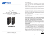
Omnitron Systems Technology OmniExtender GXPoE+/S and GXHPoE/S Owner's manual

Type
Owner's manual

This manual is also suitable for

Omnitron Systems Technology OmniExtender GXPoE+/S and GXHPoE/S are unmanaged copper gigabit Ethernet PoE Extenders. They enable the delivery of Ethernet data and Power over Ethernet (PoE) beyond the standard 100-meter limit of twisted pair copper cabling. PoE Extenders provide cost-effective connectivity for data and power to remote PoE devices where external power is not available or hard to provision. They are ideal for extending the reach of PoE networks to IP cameras, wireless access points, VoIP phones, and other PoE-powered devices.

The OmniExtender GXPoE+/S and GXHPoE/S have smart voltage-boosting technology that boosts the output voltage to 56 to 57VDC to ensure compliance with the IEEE specification between PoE Extender in a daisy chain.

OmniExtender
GXPoE+/S and GXHPoE/S
Unmanaged 30W and 60W Gigabit PoE Extender
with Booster Technology
User Manual
38 Tesla, Irvine, CA 92618 USA
Phone: (949) 250-6510; Fax: (949) 250-6514
General and Copyright Notice
This publication is protected by U.S. and international copyright laws. All rights reserved. The whole
or any part of this publication may not be reproduced, stored in a retrieval system, translated,
transcribed, or transmitted, in any form, or by any means, manual, electric, electronic, electromagnetic,
mechanical, chemical, optical or otherwise, without prior explicit written permission of Omnitron
Systems Technology, Inc.
The following trademarks are owned by Omnitron Systems Technology, Inc.: FlexPoint
TM
,
FlexSwitch
TM
, iConverter
®
, miConverter
TM
, NetOutlook
®
, OmniLight
®
, OmniConverter
®
,
OmniExtender
TM
, RuggedNet
®
, Omnitron Systems Technology, Inc.
TM
, OST
TM
and the Omnitron logo.
All other company or product names may be trademarks of their respective owners.
The information contained in this publication is subject to change without notice. Omnitron Systems
Technology, Inc. is not responsible for any inadvertent errors.
Warranty
This product is warranted to the original purchaser (Buyer) against defects in material and
workmanship for a period of two (2) years from the date of shipment. A LIFETIME warranty may be
obtained by the original purchaser by registering this product at www.omnitron-systems.com/support
within ninety (90) days from the date of shipment. During the warranty period, Omnitron will, at its
option, repair or replace a product which is proven to be defective with the same product or with a
product with at least the same functionality.
For warranty service, the product must be sent to an Omnitron designated facility, at Buyer’s expense.
Omnitron will pay the shipping charge to return the product to Buyer’s designated US address using
Omnitron’s standard shipping method.
Limitation of Warranty
The foregoing warranty shall not apply to product malfunctions resulting from improper or inadequate
use and/or maintenance of the equipment by Buyer, Buyer-supplied equipment, Buyer-supplied
interfacing, unauthorized modications or tampering with equipment (including removal of equipment
cover by personnel not specically authorized and certied by Omnitron), or misuse, or operating
outside the environmental specication of the product (including but not limited to voltage, ambient
temperature, radiation, unusual dust, etc.), or improper site preparation or maintenance.
No other warranty is expressed or implied. Omnitron specically disclaims the implied warranties of
merchantability and tness for any particular purpose.
The remedies provided herein are the Buyer’s sole and exclusive remedies. Omnitron shall not
be liable for any direct, indirect, special, incidental, or consequential damages, whether based on
contract, tort, or any legal theory.
Environmental Notices
The equipment covered by this manual must be disposed of or recycled in accordance with the
Waste Electrical and Electronic Equipment Directive (WEEE Directive) of the European Community
directive 2012/19/EU on waste electrical and electronic equipment (WEEE) which, together with
the RoHS Directive 2011/65/EU, for electrical and electronic equipment sold in the EU after July
1, 2006. Such disposal must follow national legislation for IT and Telecommunication equipment in
accordance with the WEEE directive: (a) Do not dispose waste equipment with unsorted municipal
and household waste. (b) Collect equipment waste separately. (c) Return equipment using collection
method agreed with Omnitron.
The equipment is marked with the WEEE symbol shown to indicate that it must be collected
separately from other types of waste. In case of small items the symbol may be printed only on the
packaging or in the user manual. If you have questions regarding the correct disposal
of equipment go to www.omniton-systems.com/support or e-mail to Omnitron at
Page 2
OmniExtender GXPoE+/S and GXHPoE/S
User Manual
Product Overview
OmniExtender GXPoE+/S and GXHPoE/S are unmanaged copper gigabit Ethernet
PoE Extenders. They enable the delivery of Ethernet data and Power over Ethernet
(PoE) beyond the standard 100 meter limit of twisted pair copper cabling. PoE
Extenders provide cost-effective connectivity for data and power to remote PoE
devices where external power is not available or hard to provision.
OmniExtender GXPoE+/S or GXHPoE/S 2 and 3-Port Models
Front Panel
The OmniExtender GXPoE+/S and GXHPoE/S are are 10/100/1000BASE-T
Ethernet extenders that function as both Powered Devices (PD) and Power Sourcing
Equipment (PSE). The front of the PoE Extender provides access to one RJ-45
PoE/PD port, one or two RJ-45 PoE/PSE ports and a bank of DIP-switches.
Front Panel Layout
RJ-45 Ports
The RJ-45 Ethernet ports support 10BASE-T, 100BASE-TX and 1000BASE-T
speeds, auto-negotiation and auto MDI/MDI-X crossover.
The GXPoE+/S PoE/PD port can be powered by a IEEE 802.3at (30W) or
High-Power PoE (60W) switch. When powered by IEEE 802.3at or High-Power PoE
(60W), the PoE/PSE ports can provide up to 20 watts. When a non-PoE device,
such as a laptop, is connected to the PoE Extenders for data only applications, no
power is applied.
The GXHPoE/S PoE/PD port can be powered by a IEEE 802.3at (30W) or High-
Power PoE (60W) switch. When powered by IEEE 802.3at, the PoE/PSE ports can
provide up to 20 watts. When powered by High-Power PoE (60W), the PoE/PSE
Page 3
ports can provide up to 44 watts. When a non-PoE device, such as a laptop, is
connected to the PoE Extenders for data only applications, no power is applied.
Booster Technology
Due to the voltage drop across copper cabling, the voltage at the end of an extended
topology can be below the minimum IEEE voltage requirement for the attached PD.
OmniExtender PoE Extenders have smart voltage-boosting technology that boosts
the output voltage to 56 to 57VDC to ensure compliance with the IEEE specication
between PoE Extender in a daisy chain.
Installation Procedure
1) Congure DIP-switches
2) Example Topologies
3) Determine the Amount of PoE Power Available
4) Connect Cables and Devices
5) Verify Operation
1) Congure DIP-switches
DIP-switches are located on the front of the OmniExtender PoE Extender.
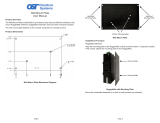
DIP-switch Bank Locations
The table below provides a description of each DIP-switch position and function.
Switch Position Function
SW1 - SW4
Left
Reserved
Right
DIP-switch Denitions for GXPoE+/S
Switch Position Function
SW1
Left Port 1 PoE/PD - Auto (Factory default)
Right Port 1 PoE/PD - Force up to 60 watts
SW2
Left Port 2 PoE/PSE - Auto (Factory default)
Right Port 2 PoE/PSE - Force up to 60 watts
SW3
Left Port 3 PoE/PSE - Auto (Factory default)
Right Port 3 PoE/PSE - Force up to 60 watts
SW4 Left / Right Reserved
DIP-switch Denitions for GXHPoE/S
Page 4
SW1: Port 1 PD - “Auto/Force”
When the Port 1 Auto/Force DIP-switch is in the default Auto position, the PoE/
PD port is in the auto mode, it will negotiate using 2 pair power if the input power
is 802.3af, or 4 pair power if the input power is 802.3at or High-Power 60 watts. 2
and 4 pair operation depends on the input power and the model of the extender.
The GXHPoE/Si negotiates PoE power on 4 pairs and the GXPoE+/Si negotiates
PoE power on 2 pairs.
When this DIP-switch is in the Force position, the PoE/PD port is in the forced mode
and congured for 4 pair operation allowing up to 60 watt input power. Forced
operation depends on the input power and the model of the extender.
SW2 and SW3: Port 2 and Port 3 - “Auto/Force”
When these DIP-switches are in the default Auto position, the port will automatically
preform the IEEE standard PoE detection, classication and powering functions to
the attached PD.
When these DIP-switches are in the Force position, a maximum of 60 watts of power
will be available to the PD.
SW4: Reserved
Page 5
2) Example Topologies
The PoE Extenders can be deployed in a daisy chain topology, dropping one or two
PDs from a single extender or dropping a PD at the end of the daisy chain. Other
combinations can be supported depending on the amount of PoE power available.
3) Determine the Amount of PoE Power Required
There are several factors to consider when extending Powered Devices over
standard copper cabling.
The power source: 802.3at (30 watts) or HPoE (60 watts)
The power required by the PD: Class of PD: 802.3af, 802.3at or 60W
The power loss in the cabling: Category 5, Category 5e or Category 6
The power consumed by the PoE Extender:
Page 6
Power Consumption per PoE Extender
PoE Extenders in
a Daisy Chain
802.3at 30W PSE High-Power 60W PSE
1st Extender 6.6 watts 9 watts
2nd Extender 5.9 watts 8 watts
3rd Extender 5.4 watts 7 watts
4th Extender 4.9 watts 6.2 watts
5th Extender - 5.7 watts
6th Extender - 5.2 watts
7th Extender - 4.9 watts
NOTE: The PoE Extender will consume less power depending on the Class of PD
attached to the PoE/PSE port.
The table below provides a summary of the distance versus available power when
multiple PoE extenders are connected.
PSE Source
Power
Number
of
Extenders
Distance
Meters / Feet
Available Power for PD
per Cable Type
Category 5 Category 5e Category 6
802.3at 30W
1 200m / 656 ft. 17.6 watts 18.6 watts 19.9 watts
2 300m / 984 ft. 11.3 watts 12.2 watts 13.5 watts
3 400m / 1,312 ft. 6.0 watts 6.7 watts 7.9 watts
4 500m / 1,640 ft. 1.2 watts 1.8 watts 2.9 watts
High-Power
60W
1 200m / 656 ft. 38.8 watts 40.8 watts 43.5 watts
2 300m / 984 ft. 29.2 watts 31.1 watts 34.0 watts
3 400m / 1,312 ft. 21.4 watts 23.2 watts 25.9 watts
4 500m / 1,640 ft. 14.8 watts 16.6 watts 19.0 watts
5 600m /1,968 ft. 9.1 watts 10.7 watts 12.9 watts
6 700m / 2,296 ft. 4.0 watts 5.4 watts 7.4 watts
7 800m / 2,624 ft. - Data Only 2.4 watts
4) Connect Cable and Devices
a. Connect the RJ-45 port on the PoE PSE equipment to the P1-PD port on the
OmniConverter GXPoE+/S or GXHPoE/S using a Category 5 or better cable.
b. Verify the PWR and P1-PD LEDs on the OmniConverter GXPoE+/S or
GXHPoE/S are functioning per the LED table on the next page.
c. Connect the RJ-45 P2-PSE or P3-PSE port on the OmniConverter GXPoE+/S
or GXHPoE/S to the Powered Device using a Category 5 or better cable.
d. Verify the P2-PSE or P3-PSE LED on the OmniConverter GXPoE+/S or
GXHPoE/S is functioning per the LED table on the next page.
Page 7
5) Verify Operation
Verify the GXPoE+/S or GXHPoE/S is operational by viewing the LED indicators.
Once power is applied through the PoE/PD port on the module, all module functions
are active. The PoE/PSE port is operational and will start detecting / classifying
once a PD device is attached to the port.
This facilitates installation and troubleshooting by ensuring each link is operational.
This is especially benecial when multiple Extenders are daisy chained.
Power - LED Indicators
Legend Indicator Description
Pwr
OFF Unit not powered
Green - ON Unit powered
Power LED Indicators
Front Panel LED Locations
PoE/PD Port - LED Indicators
Legend Location Indicator Description
P1-PD
Top and Front of the
Module
OFF No PSE power
Green - single blink Powered by 802.3af PoE 15W
Green - two blinks Powered by 802.3at PoE 30W
Green - three blinks Powered by High-Power PoE 60W
10
Located on RJ-45
Both Left & Right LED
OFF No link
Green - ON Port linked at 10Mbps
Green - Blinking at 20Hz Port data activity at 10Mbps
100
Located on RJ-45
Left LED
OFF No link
Green - ON Port linked at 100Mbps
Green - Blinking at 20Hz Port data activity at 100Mbps
1000
Located on RJ-45
Right LED
OFF No link
Green - ON Port linked at 1000Mbps
Green - Blinking at 20Hz Port data activity at 1000Mbps
PoE/PD LED Indicator
Page 8
Page 10
Specications
Description
OmniExtender GXPoE+/S and GXHPoE/S
10/100/1000BASE-T Ethernet PoE/PD to PoE/PSE Extenders
Standard Compliances IEEE 802.3, IEEE 802.3at PoE+, High-Power 60W PoE
Environmental
REACH, RoHS and WEEE
PoE/PD Mode
IEEE Alternate A (Alt A)
Frame Size Up to 10,240 bytes
Port Types
Copper: 10/100/1000BASE-T (RJ-45)
Cable Types
Copper:
EIA/TIA 568A/B, Cat 5 UTP and higher
Power Requirements
PoE/PD (input):
PoE/PSE (output):
+/-42.5 to +/-57VDC (per IEEE)
+/-50 to +/-57VDC (per IEEE)
56VDC (typical)
Dimensions
W: 3.8” x D: 4.8” x H: 1.0”
L: 96.52 mm x B: 121.92 mm x H: 25.4 mm
Weight
0.82 lbs; 372 grams
Operating
Temperature*
Commercial:
Wide:
0 to 50°C
-40 to +60°C
Humidity 5 to 95% (non-condensing)
Altitude -100m to 4,000m (operational)
MTBF (hours)
1xPD Port + 1xPSE Port: 375,000
1xPD Port + 2xPSE Ports: 317,000
Warranty Lifetime warranty with 24/7/365 free Technical Support
Standards and Compliances
Safety*
UL 60950-1
IEC 60950-1:2005+A1:2009 and
EN 60950-1:2006+A11:2009+A1:2010+A12:2011
CE Mark
EMC
EN 55032/24 CE Emissions/Immunity
IEC 61000-6-4 Industrial Emissions
IEC 61000-6-2 Industrial Immunity
EMI CISPR 32, FCC 47 Part 15 Subpart B Class A
EMS
IEC 61000-4-2 ESD: Contact: 4 kV; Air: 8 kV
IEC 61000-4-3 RS: 80 MHz to 1 GHz: 3 V/m (passed industrial rating of 10V/m)
IEC 61000-4-4 EFT: Power: 1 kV (passed industrial rating of 2 kV)
IEC 61000-4-4 EFT: Signal: 0.5 kV (passed industrial rating of 1 kV)
IEC 61000-4-5 Surge: Power: 1 kV (passed industrial rating of 2 kV)
IEC 61000-4-5 Surge: Signal: 1 kV
IEC 61000-4-6 CS: Signal: 3 Vrms (passed industrial rating of 10 Vrms)
IP Rating IP20 Protection
*Pending
PoE/PSE Port 2 - LED Indicators
Legend Location Indicator Description
P2-PSE
Top and Front of the
Module
OFF No PSE power
Green - single blink Powered by 802.3af PoE 15W
Green - two blinks Powered by 802.3at PoE 30W
Green - three blinks Powered by High-Power PoE 60W
Yellow - ON Failed PoE negotiation
Yellow - Blinking at 1Hz Can not provide the requested power
10
Located on RJ-45
Both Left & Right LED
OFF No link
Green - ON Port linked at 10Mbps
Green - Blinking at 20Hz Port data activity at 10Mbps
100
Located on RJ-45
Left LED
OFF No link
Green - ON Port linked at 100Mbps
Green - Blinking at 20Hz Port data activity at 100Mbps
1000
Located on RJ-45
Right LED
OFF No link
Green - ON Port linked at 1000Mbps
Green - Blinking at 20Hz Port data activity at 1000Mbps
P2 PoE/PSE LED Indicator
PoE/PSE Port 3 - LED Indicators
Legend Location Indicator Description
P3-PSE
Top and Front of the
Module
OFF No PSE power
Green - single blink Powered by 802.3af PoE 15W
Green - two blinks Powered by 802.3at PoE 30W
Green - three blinks Powered by High-Power PoE 60W
Yellow - ON Failed PoE negotiation
Yellow - Blinking at 1Hz Can not provide the requested power
10
Located on RJ-45
Both Left & Right LED
OFF No link
Green - ON Port linked at 10Mbps
Green - Blinking at 20Hz Port data activity at 10Mbps
100
Located on RJ-45
Left LED
OFF No link
Green - ON Port linked at 100Mbps
Green - Blinking at 20Hz Port data activity at 100Mbps
1000
Located on RJ-45
Right LED
OFF No link
Green - ON Port linked at 1000Mbps
Green - Blinking at 20Hz Port data activity at 1000Mbps
P3 PoE/PSE LED Indicator
Page 9
Customer Support Information
If you encounter problems while installing this product, contact Omnitron Technical
Support:
Phone: (949) 250-6510
Fax: (949) 250-6514
Address: Omnitron Systems Technology, Inc.
38 Tesla
Irvine, CA 92618, USA
URL: www.omnitron-systems.com
040-02000-001A 7/19
Intentionally Left Blank
Page 12Page 11
  • Page 1 1
  • Page 2 2
  • Page 3 3
  • Page 4 4
  • Page 5 5
  • Page 6 6

Omnitron Systems Technology OmniExtender GXPoE+/S and GXHPoE/S Owner's manual

Type
Owner's manual
This manual is also suitable for

Omnitron Systems Technology OmniExtender GXPoE+/S and GXHPoE/S are unmanaged copper gigabit Ethernet PoE Extenders. They enable the delivery of Ethernet data and Power over Ethernet (PoE) beyond the standard 100-meter limit of twisted pair copper cabling. PoE Extenders provide cost-effective connectivity for data and power to remote PoE devices where external power is not available or hard to provision. They are ideal for extending the reach of PoE networks to IP cameras, wireless access points, VoIP phones, and other PoE-powered devices.

The OmniExtender GXPoE+/S and GXHPoE/S have smart voltage-boosting technology that boosts the output voltage to 56 to 57VDC to ensure compliance with the IEEE specification between PoE Extender in a daisy chain.

Ask a question and I''ll find the answer in the document

Finding information in a document is now easier with AI