Page is loading ...

NEEDED MATERIALS
• (1) 1 3/8" hollow core or solid core door slab (NOT included, see page 2) .
• Paint/stain/sandpaper for use on the door and backer
board (optional).
• Scrap wood (optional, blocking for predrilling).
• Tape.
• Black paint (optional, for resizing Rustic kit for custom
width door).
NEEDED TOOLS
• Drill
• 3/32" drill bit
• 1/8" drill bit
• 5/32" drill bit
• 3/16" drill bit
• 1/4" drill bit
• 1 1/4" Forstner bit (for optional
nger pull installation)
• (2) Clamps
• Level
• Stud nder
• Phillips head screw driver
• Adjustable wrench
• Safety glasses
• Pencil/Pen
• Calculator
• Miter saw with metal cutting
blade (optional, for resizing kit
for custom width door)
• Metal le (optional, for resizing
kit for custom width door)
PRECAUTIONS AND SAFETY
• Read and fully understand ALL manufacturer’s instructions before
beginning. Failure to follow proper installation and nishing
instructions may result in the denial of warranty claims for
operational performance problems.
• Kit contents are not to be resized outside of the limits on page 5.
Modifying the kit contents beyond this will result in the denial of
warranty claims.
• Do not work alone. Two or more people are required. Use safe
liftingtechniques.
• Wear protective gear (e.g. safety glasses, gloves, ear protection, etc.).
• Operate hand/power tools safely and follow manufacturer’s
operating instructions.
• If disturbing existing paint, take proper precautions if lead paint
is suspected (commonly used before 1979). Your regional EPA
(www.epa.gov/lead) or Consumer Product Safety Commission ofces
provide information regarding regulations and lead protection.
• WARNING: Drilling, sawing, sanding or machining wood products
generates wood dust, a substance known to the State of California to
cause cancer. Use a respirator or other safeguards to avoid inhaling
wood dust.
• Hand fasten & tighten all fasteners with appropriate tool.
• If door includes glass panels, ensure drilling for handle or nger pull
will not interfere with glass.
• Only one door can be hung onto a track.
MATERIALS AND DOOR HANDLING
• Allow doors to acclimate to local conditions for at least 24 hours
before nishing.
• Store door in dry, well-ventilated area.
• Do not drag the door slab on the oor.
• Protect from exposure to direct sunlight during storage.
IF INJURY OCCURS, IMMEDIATELY SEEK MEDICAL ATTENTION!
IMPORTANT INFORMATION
MATERIALS AND TOOLS
JELD-WEN DesignGlide Barn Door Hardware System
Installation
(JII-90003)
Visit jeld-wen.com/product-support for installation and nishing
instructions and how-to videos.
©2019 JELD-WEN, Inc. This publication and its contents are owned by or licensed to JELD-WEN, Inc. or its afliates, and are protected by copyright, trademark, and other laws. Unauthorized use or duplication is prohibited.
JELD-WEN reserves the right to change product specications without notice. Please visit our website at jeld-wen.com for current information. All rights reserved.
JII-90003 04/19

2
JELD-WEN DesignGlide Barn Door Hardware System Installation
(JII-90003)
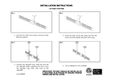
SELECTING THE CORRECT SIZED DOOR FOR THE INSTALLATION
Door Height Opening Height - 1"
Figure 2. Opening Width and Height
Figure 1. Left and Right Hand Congurations
Figure 3. Door Width, Height and Stile Width
Stile
Width
Door
Height
Door
Width
Opening
Height
Opening
Width
DOOR SPECIFICATIONS
Solid core doors must have two internal top rails.
Hollow core doors must have one internal top rail.
Door must weigh less than 120 lbs.
DOOR CONFIGURATION
This kit will accommodate a nished opening to the left or a nished
opening to the right of the barn door hardware.
DOOR HEIGHT
The height of the door used with the kit is dependent on the opening
height. Subtract 1" from the opening height to determine the door
height. If installing above thick carpet, be sure to rmly press the tape
measure to base of carpet to obtain the opening height.
Door Width Opening Width + 6"
STILE WIDTH
Denition: Stile – a vertical piece in the frame of a paneled door.
To install the included nger pull, it is recommended a door without
stiles is used, or a door with stiles that are at least 4 11/16"
in width, 5" in width if door includes glass panels.
DOOR WIDTH
The selected door should be no wider than the kit's rail width.
Recommended door width is least 6" wider than the opening width.

4
9
5
6
11
14
LAG M8 X 90mm 5/6
TRIGGER ASSEMBLY 2
21
LOCKING NUT, M4 4
20
WASHER, M6 4
19
SOCKET HEAD, M4 X 35mm 4
23
MODERN HANDLE 1
MODERN KIT RUSTIC KIT
26
RUSTIC HANDLE 1
24
BUTTON HEAD SCREW,
M6 X 55mm 2
22
FINGER PULL 1
18
SOFT CLOSE 2
16
FLOOR GUIDE ASSEMBLY 1
17
FLOOR ANCHOR 1
HANGER 2
LEFT END CAP 2 RIGHT END CAP 2
13
PAN HEAD, #14 X 2 1/2"
15
FLAT HEAD, #14 X 2 1/2" (4)
27
FLAT HEAD, #8 X 3/4" (4)
12
PAN HEAD, #10 X 1" (4)
8
FLAT HEAD
#9 X 21/2" 10/12
7
STANDOFF 5/6
WASHER, M8 5/6
10
ALLEN WRENCH, 3mm 1
25
ALLEN WRENCH, 4mm 1
PASSIVE END STOP 2
SOFT CLOSE TRACK 1
RAIL 2
BACKER BOARD (1)
2
3
1
17
16
12
11
3
18
21
19
20
2
9
10
7
5
6
4
11
12
15
14
3
24
22
23 OR 26
13
1
3
JELD-WEN DesignGlide Barn Door Hardware System Installation
(JII-90003)
KIT CONTENTS

4
JELD-WEN DesignGlide Barn Door Hardware System Installation
(JII-90003)
30 1/2"
Stile Width
30 1/2"
Figure 5. Aligning Finger Pull Drill Guide to Door.
Figure 4. Aligning Handle Drill Guide to Door.
STEP 1: DOOR HARDWARE INSTALLATION
Predrill for handle.
If the door design selected for this kit includes stiles, it is recommended
that the handle is installed at the center of the stile. This can easily be
achieved through the use of the rulers included on the Handle Drill
Guide, on Page 13. Simply measure the stile width of the door, and fold
the guide along the same measurement, shown in Figure 4.
If the door does not include stiles, fold as indicated on guide.
Before predrilling the door, ensure the handle is being installed on the
side of the door that will be closest to the opening when the door is in
the opened position.
Predrilling handle
1. Remove the Handle Drill Guide on Page 13.
2. Fold the guide along rulers at the correct stile width.
3. Place the bottom edge of the Handle Drill Guide 30 1/2" above
the bottom of the door as seen in Figure 4.
4. Tape the Handle Drill Guide in place.
5. Predrill for kit’s handle as indicated on guide, to diameter and
depth prescribed.
Note: If drilling for the Modern handle apply blocking to the back of
the door, clamping it in place under the area of door that will be drilled
through. This will help create a clean hole through the door.
Predrilling for finger pull.
An optional finger pull is included in the kit. Before installing, ensure
the door design adheres with the stile width guidelines on Page 2.
1. Remove the Finger Pull Drill Guide on Page 14.
2. Fold as indicated on guide and wrap guide around door, placing the
guide on the backside of the door, aligning the bottom edge 30 1/2"
above the bottom of the door as shown in Figure 5.
3. Tape the nger pull guide in place.
4. Predrill to diameter and depth indicated on guide.
Note: After predrilling for the handle and/or finger pull, sand/paint/
stain the door if desired.

5
JELD-WEN DesignGlide Barn Door Hardware System Installation
(JII-90003)
STEP 2: SIZING RAIL AND PREDRILLING FOR END CAPS
Figure 7. Matching End Cap to Rail
Figure 8. Marking End Cap on Rail
Figure 9. Rail Predrilled for End Cap
⑪
③
⑪
③
③
Rail Width - Door Width
2
A =
.
A
A
A
A
DesignGlide hardware is capable of being cut down 6" from the kit’s
stock rail ③ length to support custom width doors.
Rail Width
Door Width
Figure 6. Cutting Rails for Custom Width Door
Kit Max Door Width Minimum Door Width
36" (72" track) 36" 30"
42" (84" track) 42" 36"
Table 2. Minimum Door Width
③
③
If you are using a door width that is smaller than the kit’s stock rail
width, follow the steps below. If not, skip to the next step, Predrilling
for End Caps.
Sizing Rails
1. Both the top and bottom rails ③ need to be cut symmetrically. Use
the formula below to determine your cut dimension 'A'.
2. Mark each rail at the 'A' dimension.
3. Slowly cut both rails symmetrically with a miter saw, using a metal
cutting blade.
4. Finish and smooth all edges with le/ne sand paper.
5. If cutting a rustic kit, renish ends with black paint.
Predrilling for End Caps.
Place rail in configuration seen in Figure 7.
1. Place an end cap ⑪ inside the rail ③, ensuring it ts ush with end
of the rail.
2. Rotate the end cap to the top of the rail as shown in Figure 8.
3. Mark the end cap’s fastening hole on rail.
4. Predrill through the rail using a 1/4" drill bit.
5. Repeat for the remaining ends of both rails.
Note: Do not install the end caps at this time.

WALL
WALL
WALL
WALL
1
2
3
4 5 6
6
JELD-WEN DesignGlide Barn Door Hardware System Installation
(JII-90003)
STEP 3: TOP AND BOTTOM RAIL INSTALLATION
Top
Bottom
Top Rail
Bottom Rail
Figure 10. Rail Orientation
Figure 11. Mounting Pattern
Figure 12. Attach Rail to Bottom of Door
Pan Head, #10 x 1" (2)
Pan Head, #14 x 2 1/2" (2)
Figure 13. Attach Rail and Hangers to Top of Door
Flat Head, #14 x 2 1 /2" (4)
Predrill bottom rail.
1. Align one of the two rails ③ to bottom of door, in the conguration
shown in Figure 10.
2. Mark the center of holes 1, 3, 4 and 6 as shown in Figure 11, (holes 2
and 5 will not be used on the bottom rail), remove the rail.
3. Predrill holes 1 and 6 with an 1/8" bit, 3/4" deep.
4. Predrill holes 3 and 4 with a 5/32" bit, 1 7/8" deep.
5. Realign rail to the bottom of the door in the same conguration
as the door was predrilled.
6. Fasten the rail to the bottom of the door with (2) #14 x 2 1/2"
pan head screws ⑬.
7. Install the end caps into holes 1 and 6 using (2) #10 x 1" pan head
screws ⑫.
Predrill top rail.
1. Align other rail ③ with the top of door, in the conguration shown in
Figure 10.
2. Mark the center of all holes, remove rail.
3. Predrill holes 1 and 6 with an 1/8" bit, 3/4" deep.
4. Predrill holes 2, 3, 4, and 5 with a 5/32" bit, 1 7/8" deep.
5. Realign rail to the same conguration as the door was predrilled.
6. Place hangers ⑭ with the stem of the hanger aligned with the at
wall of the rail.
7. Fasten the hangers in place through holes 2, 3, 4, and 5 using
(4) #14 x 2 1/2" at head screws ⑮.
See Figure 26 for a vertical section
of a complete installation.
③
③
or
⑪
③
⑬
⑫
⑫
⑭
③
⑮
⑮
⑬

Flat Head, #9 x 2 1 /2" (10/12)
⑧
7
JELD-WEN DesignGlide Barn Door Hardware System Installation
(JII-90003)
STEP 4: BACKER BOARD INSTALLATION
Figure 14. Predrilling Backer Board
Table 3. Determining Backer Board Offset
Figure 16. Backer Board Stud Alignment
Backer Board Height Door Height (without the door rails) + 4 1/4"
Table 4. Door Height/Backer Board Height
Predrill backer board.
1. Clamp the track ② to the backer board ① , 1" above the bottom edge.
2. Predrill through the 3/8" holes using a 3/16" bit, through the
backer board.
Determine backer board offset.
The backer board ① offset is referenced from the inner surface of
the door opening to the end of the backer board. This position will
coincides with the closed position of your new DesignGlide barn door.
Measure the width of your new door and match it to the value for the
backer board offset found in table 3.
Determine backer board placement.
The height of the backer board can be determined via the door height
using Table 4.
Notes to consider:
• The floor below barn door must be level. If not, take opening and
backer board measurements from highest point.
• If installing into thick carpet, firmly press the tape measure to
the base of the carpet before making the backer board height
measurement.
Kit Size
(Track Length)
Door Width
Backer Board
Offset
36" (72" track)
30" 8"
30 1/2" 7"
31" 6"
31 1/2" 5"
32 4"
32 1/2" 3"
33"
3"
33 1/2"
34"
34 1/2"
35"
35 1/2"
36"
Kit Size
(Track Length)
Door Width
Backer Board
Offset
42" (84" track)
36" 8"
36 1/2" 7"
37" 6"
37 1/2" 5"
38" 4"
38 1/2" 3"
39"
3"
39 1/2"
40"
40 1/2"
41"
41 1/2"
42"
Predrill the backer board for stud attachment.
1. Using a stud nder, mark all stud locations on the wall that overlap
with the placement of the backer board ①.
2. Mark stud locations on backer board.
3. With the backer board held in position, and leveled, predrill for the
included wood screws using 1/8" bit (two screws per stud, evenly
spaced vertically on backer board. The 72" kit comes with mounting
hardware ⑧ for 5 studs, the 84" kit comes with mounting hardware
⑧ for 6 studs).
Note: After completing all predrilling of the backer board, sand/paint/
stain the board if desired.
Attach backer board to the wall
Once the desired nish is achieved, fasten the backer board to the wall
with the included #9 x 2 1/2" at head screws ⑧.
Figure 15. Backer Board Placement
Backer
Board
Height
Opening
Height
Floor Guide
Opening
Width
Backer
Board
Offset
①
②
1" 1"
①

JELD-WEN DesignGlide Barn Door Hardware System Installation
(JII-90003)
8
STEP 5: SOFT CLOSE AND TRACK INSTALLATION
Install soft close to track.
1. Align the soft closes ⑱ on the track as shown in Figure 17, with
movable catches loaded towards the center of the track.
2. Verify plastic spacers are inserted into ends of soft close mechanisms,
aligned with fastening holes.
3. Fasten the soft close to the track using the supplied M4 x 35mm
socket cap screws ⑲, M6 washers ⑳ and M4 locking nuts .
4. Fasten with supplied 3mm Allen wrench ⑩.
Figure 17. Soft Close Orientation
Fastening track to backer board.
1. Secure the rst and last holes in the track ② using a 90mm lag bolt
④, M8 washer ⑥, passive end stop ⑤ and standoff ⑦.
2. Secure the rest of the holes with a 90mm lag bolt ④, M8 washer ⑥
and standoff ⑦.
Figure 18. Track Assembly
STEP 6: FLOOR GUIDE INSTALLATION
1. Reference Figure 15 on Page 7, to determine the installation location
of the oor guide, relative to open/closed positions of the system.
2. Using a pencil, mark 2" away from the wall and 1 1/2" in from the
interior edge of the opening, reference gure 20.
Note: If there is a baseboard, take its thickness into consideration.
3. Predrill with a 3/32" bit, 1" deep. If installing into a concrete oor,
predrill with a 1/4" bit, 1 3/8" deep.
4. Assemble the oor guide ⑯ (if not pre-assembled) as shown in Figure 19.
If installing into concrete, use oor anchor ⑰ in predrilled hole.
5. Hand tighten the oor guide in place, ensuring the rubber base has
the ability to rotate.
Figure 19. Floor Guide Assembly
Figure 20. Location of the oor guide
④
⑥
⑦
④
⑤
⑥
⑦
②
⑰
⑯
⑯
2"
1 1/2"
Orient both soft close mechanisms with
movable catches toward center of track
⑲
⑱
⑳
⑩
Plastic Spacer
①
Rubber Base

9
JELD-WEN DesignGlide Barn Door Hardware System Installation
(JII-90003)
Hang barn door on track.
1. Using two people, lift the door vertically and place the bottom rail
over the oor guide .
2. Keeping the bottom rail over the oor guide ⑯, lift the door
vertically and place hangers on the track .
Figure 21. Hanging Barn Door
STEP 7: HANGING BARN DOOR
A A
B
B
B
A
⑯

10
JELD-WEN DesignGlide Barn Door Hardware System Installation
(JII-90003)
MODERN KIT
Install the Modern handle.
1. Secure Modern handle using (2) M6 x 55mm button head
screws with supplied 4mm Allen wrench .
RUSTIC KIT
Install the Rustic handle.
1. Secure Rustic handle in place with (4) #8 x 3/4" at head screws .
STEP 8: HANDLE AND OPTIONAL FINGER PULL INSTALLATION
Flat Head, #8 x 3/4" (4)
Button Head, M6 x 55mm (2)
Figure 23. Rustic Handle Installation
Figure 22. Modern Handle Installation
2. (Optional) Press nger pull into predrilled hole.
2. (Optional) Press nger pull into predrilled hole.

A
B
22 OR 24
11
JELD-WEN DesignGlide Barn Door Hardware System Installation
(JII-90003)
STEP 9: INSTALL AND ADJUST SOFT CLOSE TRIGGERS
Attach soft close triggers.
1. Slide the door to the center of the track.
2. Check the position of soft close catch. Both should be loaded towards
the center as noted in Step 5: Soft Close and Track Installation, Figure 17.
3. Remove the anti-jump rod from the trigger assembly.
4. Slide the trigger onto the rail using the measurements found in
table 5.
a. Measurement 'A' is taken from the edge closest to the handle, as
shown in gure 25.
b. Measurement 'B' is taken from the opposite edge of 'A'.
5. Secure the triggers⑨ in place with the set screws using the supplied
3mm Allen wrench ⑩ as seen in Figure 24.
6. Secure the anti-jump rod back into the trigger block using the
supplied 3mm Allen wrench.
Note: Fine adjustments to the open and closed positions of the door by
loosening the set screws and sliding to the desired position and
re-tightening the set screw in the trigger.
Anti-Jump
Rod
Figure 24. Trigger Installation
Figure 25. Trigger Alignment
Figure 26. Vertical Section
Table 5. Trigger Locations
Kit Size
(Track Length)
Door Width A B
36" (72" track)
30" 5 1/2"
1/2"
30 1/2" 6 1/2"
31" 7 1/2"
31 1/2" 8 1/2"
32 9 1/2"
32 1/2" 10 1/2"
33"
10 1/2"
4 1/2"
33 1/2" 5"
34" 5 1/2"
34 1/2" 6"
35" 6 1/2"
35 1/2" 7"
36" 7 1/2"
Kit Size
(Track Length)
Door Width A B
42" (84" track)
36" 5 1/2"
1/2"
36 1/2" 6 1/2"
37" 7 1/2"
37 1/2" 8 1/2"
38" 9 1/2"
38 1/2" 10 1/2"
39"
10 1/2"
4 1/2"
39 1/2" 5"
40" 5 1/2"
40 1/2" 6"
41" 6 1/2"
41 1/2" 7"
42" 7 1/2"
Set Screws
Hanger
⑭
Soft Close Trigger ⑨
Anti-Jump Rod ⑨
Top Rail ③
Soft Close Track ②
Door
⑨
⑩
⑨

12
JELD-WEN DesignGlide Barn Door Hardware System Installation
(JII-90003)
STEP 10: INSTALL TOP END CAPS TO COMPLETE INSTALLATION
Using (2) #10 x 1" pan head screws ⑫, secure both end caps ⑪ in place.
Pan Head, #10 x 1" (2)
Figure 27. End Cap Installation
⑫
⑫
⑪

8 6 4 2
8
6
4
2
357 1
1
3
5
7
A
A
B
5 1/8" 8 1/2"
For Rustic Handle
Predrill with 1/8" bit
5/8" deep
(A):
For Modern Handle
Predrill with 1/4" bit
through door
(B):
Fold guide at stile width
-or-
If door does not contain stiles, fold at 8"
30 1/2" from bottom of page to bottom of door
30 1/2" from bottom of page to bottom of door
1"
1"
13
Handle Drill Guide


Predrill with 1 1/4" Forstner bit
5/8" deep
30 1/2" from bottom of page to bottom of door
30 1/2" from bottom of page to bottom of door
Bend around edge of door
F
i
n
g
e
r
P
u
l
l
F
i
n
g
e
r
P
u
l
l
1"
1"
14
Finger Pull Drill Guide

/