
Tip. Montagnani - Modena - Cod. 533939 0203 -MADE IN ITALY


3
GENERAL INFORMATION
DESTINED TO THE END USER
ENVIRONMENT PROTECTION
Packing disposal
Sort packing into different materials (cardboard, polystyrene
etc.) and dispose of them in accordance with local waste
disposal laws.
This appliance complies with the following European Directives:
- 73/23/EEC regarding "Low Voltage".
- 89/336/EEC regarding "Electromagnetic Disturbances".
- 90/396/EEC regarding “Gas appliances”
- 89/109/EEC regarding "Materials in contact with food"
- Moreover the above mentioned Directives comply with Directive
93/68/EEC.
- This household appliance has been designed for cooking and
it must therefore be used for this purpose only.
DEAR CUSTOMER,
• Carefully read these instructions before using the appliance and
keep them for future consultation.
• Keep potentially hazardous packaging (plastic bags, polystyrene
etc.) out of the reach of children.
WARRANTY
Your new appliance is covered by a warranty.
The warranty certificate is herewith enclosed. If it is missing, ask
the retailer for it indicating purchasing date, model, and data plate
number which are printed on the data nameplate identifing the
appliance.
Keep the part destined to you, and in case of necessity, show it
to the Technical Service together with the receipt bill.
If you do not follow this procedure, the technical service will be
compelled to charge you with all the fees of each eventual reparation.
You can find the original spare parts only in our Technical Service
and Spare Parts Authorised Centres.
TECHNICAL AFTER SALES SERVICE
Before leaving the factory, this appliance has been tested and set
up by skilled personal, in order to give the best performance results.
Each reparation or set up that could be necessary afterwards,
must be carried out with a great care and attention.
For this reason, we reccommend you to keep always in touch with
the Sales Centre or with our nearer After Sales Service. Specify
always the kind of problem and the model of your appliance.
INDEX FOR FIRST PART (for the user)
Use of the gas work-top page 3
Use of the glass ceramic work-top page 3-4
Use of the gas oven page 4-5
Use of the gas grill page 5
Use of the electric grill page 5
Use of the turnspit page 5
Use of the electric oven page 6-7
Use of control devices page 8-9-10-11
Cleaning page 11-12
RECCOMANDATIONS AND PRECAUTIONS
ATTENTION:
- Before using the appliance, do not forget to remove the plastic
films protecting some parts of the appliance (facia-panel, parts
in stainless steel, etc.)
- Do not use the appliance as a space heater.
- When the appliance is not in use, we recommend
to disconnect
the current and to close the gas general tap.
IN CASE OF FIRE:
• In case of fire, close
immediately the main valve of the gas
pipe line, disconnect current
and never pour water on firing
oil in any case.
• Do not store flammable products or aerosol containers near the
burners, and do not vaporize them near lighted burners.
FOR YOUR SAFETY AND THE ONE OF YOUR CHILDREN.
• Do not store items that are attractive to children above or near
the appliance.
• Keep children well away from the appliance: do not forget that
some parts of the appliance or of the pans become very hot and
dangerous during use, and also for all the time necessary to
cool down.
• In order to avoid any unintentional fall down, pan handles should
be turned to the back of the cooker, not out to the room or over
adjacent burners.
• When cooking, do not use clothes with large flaving and
flammable sleeves; in case of firing you can suffer very serious
harms.
FOR APPLIANCES WITH GLASS COVER LID
While using the appliance, make sure that the glass lid does not
touch any pan. After use never close the glass lid while the burners
or the electric hotplates are still hot.
WARNING - OVEN:
When the oven or the grill are in use, accessible parts can
become very hot; it is necessary to keep children well away
from the appliance.
- Never cook food on the lower wall of the oven.
- In case of careless use, in proximity of the oven door hinges,
there is hurt danger.
- Do not let children sit down or play with the oven door. Do not
use the drop down door as a stool to reach above cabinets.
WARNING - GRILL:
Always use the grill with oven door half-open (at the first hinge
release), and with knobs protection installed, as per the specific
instructions provided in the grill use.
For safety and standard reasons, it is forbidden to use at the
same time the gas oven burner together with the electric/gas
grill.
WARMING CABINET
You must not place inflammable materials or plastic utensils in the
warming cabinet (placed below the oven).
INDEX FOR SECOND PART (for the installer)
Appliance installation page 12
Rooms ventilation page 13
Gas connection page 13
Electric connection page 14
Gas adjustments page 14-15
Appliance care page 15-16

4
WORK-TOP USE
FIRST PART
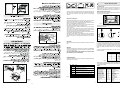
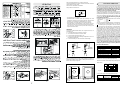
USING GAS BURNERS
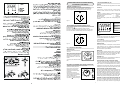
The following symbols are on the control panel next to each knob:
- Black circle gas off
- Large flame maximum setting
- Small flame minimum setting
The minimum position is at the end of the anti-clockwise rotation
of the knob. All operation positions must be chosen between the
positions of max. and min., never choose them between max. and
off.
MANUAL IGNITION
To turn on a burner, approach a match to it, press the knob
corresponding to the selected burner and turn it anticlockwise to
the minimum position.
ELECTRIC IGNITION (optional)
To turn on a burner, press the knob corresponding to the selected
burner and turn it anticlockwise to the minimum position;
simultaneously pressing the electric ignition button on the control
panel marked with symbol
.
In case there is no electric current, the burner can also be lighted
using a match.
AUTOMATIC ELECTRIC IGNITION (optional)
To turn on a burner, press the knob corresponding to the selected
burner and turn it anticlockwise to the minimum position. Keeping
the knob pressed, the electric automatic ignition of the burner will
be started up.
In case there is no electric current, the burner can also be lighted
using a match.
APPLIANCES WITH SAFETY VALVE (optional)
Follow the same procedure described above to ignite the burners.
In this case, however, once you have turned the knob to the open
setting, hold it pressed in for 10 seconds.
If for any reason the burner flame goes out, the safety valve
automatically shuts off the gas supply to the burner in question.
ENERGY SAVING TIPS
• The diameter of the pan bottom should be the same as that of
the burner. The burner flame must never come out from the pans
diameter.
• Use flat-bottomed pans only.
• Whenever possible, keep a lid on the pan while cooking.
You will not need as much heat.
• Cook vegetables, potatoes, etc. with as little water as possible
to reduce cooking times.
Fig.1
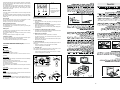
USING ELECTRIC HOTPLATES
When using an electric hotplate for the first time or after a long
period of disuse, turn the knob to 1 and let it heat for about 20
minutes to eliminate any possible moisture absorbed by the internal
insulating material.
- Dry the bottom of the pan before placing it on the hotplate.
- Turn the hotplate on only after placing the pan on it.
The hotplate is controlled by a commutator. Turn the knob until
position 1 to turn the hotlplate on. A warning light on the control
panel will inform you if the plate is on or off.
Suggested settings (guide)
Fig. 2
0
1
4
2
3
5
6
0
1
2
3
4
5
6
ENERGY SAVING TIPS
• The diameter of the saucepan must be the same or slightly larger
than that of the electric hotplate. Never use a pan which is smaller
than the electric hotplate.
• Use flat-bottomed pans only.
• Preferably cover pans with a lid to permit cooking at a lower
heat.
• Always cook vegetables and potatoes, etc. in as little water to
reduce cooking times.
CERAMIC WORK-TOP
The work-top is fitted with cooking areas of different diameter and
power. The positions are clearly marked. The heating occurs only
within the diameters marked on the work-top.
For efficient cooking and energy saving, it is essential to use only
suitable saucepans.
Cookware with rough bottoms should not be used since these can
scratch the ceramic surface. Before use, make sure that pan
bottoms are clean and dry.
Pans should have the same diameter as the cooking zone they
are used on.
When cold, pan bottoms should be slightly concave, as they
expand when they are hot and lie flat on the surface of the hob.
This transfers the heat best.
The best thickness for pan bottoms is 2-3 mm in case of enamelled
steel and 4-6 mm for stainless steel with sandwich type bottoms.
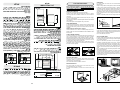
There is a simple way of checking whether the pan bottom is of
the right shape (when cold).
Rest the middle of the bottom at an angle against the straight
edge of a table and slip a few strips of typing paper between them.
As a guide five to ten pieces of paper is correct for enamelled
steel pans and two to five strips for stainless steel (the higher
number applies to the larger sizes of pan).
Fig. 4
Fig. 3
0 Off
1 Very slow
2Low
3 Medium-
Low
4 Medium
5 High
6 Very high
For melting butter, chocolate, etc.
For heating small amounts of liquid.
For heating larger amounts of liquid.
For preparing slow-cooking creams and sauces.
For thawing frozen foods and cooking stews, cooking
at boiling or lower temperatures.
For boiling foods, roasting delicate meats and fish.
For braising chops and steaks, for large meat soups.
For boiling large amounts of water and frying.
Pos. Heat Use
Intensity

Use of the oven
Before using the oven for the first time, heat it to the maximum
temperature for about 30 minutes to eliminate smokes and
unpleasant smells produced by internal components.
Manual ignition of the burner
Open the oven door and bring a light match near the central hole
A placed on the oven bottom.
5
Fig. 5
These rules are very important. If they are not followed there will
be a great loss of heat and energy, and the heat not absorbed by
the saucepan will spread to the hob, frame and surrounding
cabinet.
Using the cooking hob.
The first few times the hob is used, it may give off acrid, burning
smells. These will disappear completely with repeated use.
Each cooking area has a selector knob on the appliance control
panel for setting different temperature levels.
For normal cooking, place the saucepan on the desired area of
the hob and set the knob to the maximum heat.
A warning light on the control panel will inform you if the cooking
area is on or off.
Some of the cooking work-tops have an indicator light between
the two front cooking areas, which lights up when one or more of
the cooking areas goes above the temperature of 60°C.
The indicator light switches off only when the temperature of the
cooking areas goes below about 60°C.
After a few minutes, when the contents of the saucepan are boiling,
turn the knob to a lower position, depending on the quantity, so
that the saucepan does not splash over and there is no waste of
heat.
Important
Be very careful about the safety of children when using the ceramic
hob.
Attention
Although the hob surface is very tough, it is certainly not unbreakable
and it can be damaged, especially if pointed or hard objects fall
on it with a certain force.
Do not use the hob if the surface is broken or cracked; contact
the assistance service immediately.
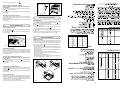
GUIDELINE TABLE
The actual settings depend on the quantity and quality of the food
and the type of saucepan.
Fig. 6
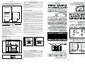
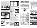
USE OF THE GAS OVEN
TAB. A
Fig. 8
FOOD TEMP. °C FOOD TEMP. °C
MEAT PASTRY
ROASTED PORK 185-210 FRUIT CAKE 220
ROASTED BEEF 250 MARGHERITA CAKE 190
ROASTED VEAL 220 BRIOCHES 175
ROASTED LAMB 220 SCONES 235
ROASTED HARE 230 RING-SHAPED CAKE 190
ROASTED RABBIT 235 PUFF-PASTE 200
ROASTED TURKEY 220 GRAPES CAKE 200
ROASTED GOOSE 235 STRUDEL 180
ROASTED DUCK 225 SAVOIA BISCUIT 290
ROASTED CHICKEN 235 APPLE FRITTER 200
ROAST-BEEF 200-225 PUDDING 200
FISH 200-225 TOAST 250
BREAD 230
0 Off
1 Very slow
2Low
3 Medium-
Low
4 Medium
5 High
6 Very high
For melting butter, chocolate, etc.
For heating small amounts of liquid.
For heating larger amounts of liquid.
For preparing slow-cooking creams and sauces.
For thawing frozen foods and cooking stews, cooking
at boiling or lower temperatures.
For boiling foods, roasting delicate meats and fish.
For braising chops and steaks, for large meat soups.
For boiling large amounts of water and frying.
Pos. Heat Use
Intensity
Turn the corresponding knob anti-clockwise, placing the index on
the maximum position.
Burner with safety device
For burners fitted with safety device, it it necessary to keep on
pressing the concerned knob for about 10 seconds after the ignition.
In this way the safety valve will be started up. If for any reason the
burner flame goes out, repeat the procedure as described above.
When you will be sure that the burner is on, close softly the oven
door.
To obtain the desired temperature, turn the knob index to the
selected number.
Wait at least 15 minutes before introducing the food, in order to
reach the desired temperature. Below you will find an indicative
cooking table (TAB.A).
Knob position Temperature °C
1 140 °C
2 150 °C
3 160 °C
4 170 °C
5 190 °C
6 210 °C
7 230 °C
8 250 °C
Fig. 9
1
8
= CLOSED
= MIN.
= MAX
= GRILL
1
2
8
3
4
5
6
7
1
2
8
3
4
5
6
7
Fig. 7
A

ELECTRIC GRILL
Some appliances with gas oven can be fitted with an electric grill.
a – To operate the electric heating element, press button which
lights up to indicate that the grill is working.
Symbol
, in the models fitted with turnspit, corresponds also
to the turnspit operation.
b – In some other appliances the electric grill can be operated
turning the knob clockwise on position .
A warning light on the control panel will light up to inform you that
the grill is on.
- In both cases “a-b” the electric grill must be used with half-open
door (see fig.11A) and deflector placed as in (see fig.11B).
USE OF THE ELECTRIC GRILL
6
To turn the oven light on, press switch .
Electric ignition of oven burner (optional)
The oven door must always be completely open, before the
burner ignition.
Turn the knob anti-clockwise to the maximum position, then press
button
to ignite the burner.
In case there is no electric current, the burner can also be lighted
using a match.
Automatic electric ignition (optional)
To ignite the burner, press the knob and turn it anti-clockwise to
the maximum position. Keep it pressed to start up the automatic
ignition of the burner.
In case there is no electric current, the burner can also be lighted
using a match.
USE OF THE GAS GRILL
Manual ignition of the grill
Open the oven door, then turn the oven knob to the right and place
it on the grill position .
Bring a light match near the holes of the burner placed on the
oven upper part.
Burner with safety device
Repeat the above mentioned procedure, and press the oven knob
at the same time. When the burner is on, keep the knob pressed
for about 10 seconds. In this way the safety valve will be started
up. If for any reason the burner flame goes out, repeat the procedure
as described above.
Electric ignition of grill burner (optional)
The oven door must always be completely open, before the
burner ignition.
Turn the knob clockwise to the grill position , then press button
to ignite the burner.
In case there is no electric current, the burner can also be lighted
using a match.
Automatic electric ignition (optional)
To ignite the burner, press the knob and turn it clockwise to the
grill position . Keep it pressed to start up the automatic ignition
of the burner.
In case there is no electric current, the burner can also be lighted
using a match.
How to use the gas grill.
The appliance is foreseen to operate the grill with half-open door
(fig.11A) and with the grid on the third shelf from the oven bottom,
at about 12 cm from the surface, and with the deflector placed as
in (fig.11B). The user can change the shelves, depending on his
personal whishes and on the different food .
Heat the oven 5 minutes before introducing the food.
Fig. 11
A
B
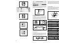
USE OF THE TURNSPIT
TURNSPIT (optional)
The turnspit can be fitted with an electric heating element or with
a gas burner. To operate the electric heating element, repeat the
operations described in paragraph ELECTRIC GRILL. To turn on
the gas burner, repeat the operations described in paragraph GAS
GRILL and press switch
.
- Put the food in spit L, paying attention to block it within the two
forks F and to balance it, in order to avoid any unnecessary
effort to motor R.
- Put the spit on support G, after having put its opposite end into
hole P of motor R.
- Place the drip-tray with a little water under the spit.
- Fit the knobs deflector and place the door in half-open position
as in (see fig.11A-B).
- Start up motor R and turn the grill on.
- To remove the shit, operate in the apposite direction using knob
S and a protecting glove in isolating wool.
Fig. 12
S
F
L
G
P
R
Fig. 10
S
L
F
R
P
G
R
P
G
F
S
L
G

7
USE OF THE ELECTRIC OVEN
FIRST PART
The first time the oven is used, it may give off acrid smells, caused
by the first heating of isolating panels glue surrounding the oven
(it is necessary to heat up the oven at the maximum
temperature for about 30-40 minutes with closed door).
It is something normal, and in case it will occur, wait for the smoke
to stop before introducing the food into the oven.
The oven is fitted with: a rod shelf for cooking food contained in
oven dishes or placed directly on the rod shelf itself, a drip-tray
for cooking sweets, biscuits, pizzas, etc., or for collecting juices
and fats from food cooked directly on the rod shelf.
Note: The following tables give the main points for cooking some
of the most important dishes. The cooking times recommended
in these tables are approximate. After a few tries, we are sure that
you will be able to adjust the times to get the results you want.
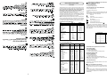
Conventional cooking table TAB.B
Fan oven cooking table TAB. C.
1 – Thermostat knob combined to oven selector (optional)
NATURAL CONVECTION OVENS
The oven is fitted with:
• a lower heating element;
• an upper heating element.
In some models the oven can be fitted with:
• a lower heating element;
• an upper heating element;
• a fan.
It is possible to select the desired temperature into the oven by
turning clockwise the thermostat knob (see fig.13), and depending
on the models, one or more functions:
Oven off
Oven light
1 ÷ 11 Upper + lower heating element on
Fan motor on
Upper heating element on
Lower heating element on
Grill element on (turnspit optional )
NOTE: Upper + lower heating elements are turned on between 1
and 11 for static ovens, or also the fan for air forced static ovens.
In some models the silk-screen printing between 1 and 11 has
been replaced by a silk-screen printing in “°C” included between
50°C and 250°C.
Fig. 13
Position Knob °C
150
270
390
4 110
5 130
6 150
7 170
8 190
9 210
10 230
11 250
Thermostat knob separate from oven selector
AIR FORCED OVENS
The oven is fitted with:
• an upper heating element;
• a circular heating element surrounding the fan.
MULTIFUNCTIONAL OVEN
The oven is fitted with:
• a lower heating element;
• an upper heating element;
• a circular heating element surrounding the fan.
N.B.: Always set the temperature on the thermostat knob before
selecting any of the functions.
Oven thermostat knob
To obtain an oven temperature between 50°C and 250°C, turn
the knob clockwise.
2 – Oven commutator knob (optional)
Depending on the type of oven, it is possible to select one of the
following functions turning the commutator knob clockwise.
Note:
In both cases 1 and 2 all the functions mentioned above switch
the oven internal light on. A warning light on the control panel will
stay lit until the temperature is reached; after it will light up
intermittently.
Dish Temp. °C. Minutes
Fish 180-240 acc. to size
Meat
Roast ox 250 30 per kg.
Roast veal 200-220 60 per kg.
Chicken 200-240 50 about
Duck and goose 220 acc. to weight
Leg of mutton 250 30 per kg.
Roast pork 250 60 per kg.
Soufflets 200 60 per kg.
Sweets (pastries)
Tea-cake 160 50-60
Sponge finger 160 30-50
Shortcrust pastry 200 15
Puff pastry 250 15
Fruit flan 200-220 30
Meringues 100 60
Quiches, etc. 220 30
4 quarters 120-140 60
Buns 160-180 45
Dish Temp. °C. Minutes Weight kg.
Firs courses
Lasagne 200-220 20-25 0,5
Oven pasta 200-220 25-30 0,5
Creole rice 200-230 20-25 0,5
Pizza 210-230 30-45 0,5
Meat
Roast veal 160-180 65-90 1-1,2
Roast pork 160-170 70-100 1-1,2
Roast ox 170-190 40-60 1-1,2
Roast beef joint 170-180 65-90 1-1,2
Roast fillet beef (rare) 180-190 40-45 1-1,5
Roast lamb 140-160 100-130 1,5
Roast chicken 180 70-90 1-1,2
Roast duck 170-180 100-160 1,5-2
Roast goose 160-180 120-160 3-3,5
Roast turkey 160-170 160-240 5 approx.
Roast rabbit 160-170 80-100 2 approx.
Roast hare 170-180 30-50 2 approx.
Fish 160-180 acc. to weight
Sweets (pastries)
Fruit flan 180-200 40-50
Plain sandwich cake 160-180 35-45
Sponge sandwich cake 200-220 40-45
Sponge cake 200-230 25-35
Currant cake 230-250 30-40
Buns 170-180 40-60
Strûdel 160 25-35
Cream slices 180-200 20-30
Apple fritters 180-200 18-25
Sponge finger pudding 170-180 30-40
Sponge finder biscuits 150-180 50-60
Toasted sandwiches 230-250 7
Bread 200-220 40

8
Use of the oven
Note: ovens with separate thermostat and commutator.
When the functions are used, place the thermostat
knob between 180 ÷ 200°C as maximum temperature.
ATTENTION:
The temperature shown on the control panel corresponds to the
temperature in the oven centre only when the functions selected
are or
.
When you turn the control knob to this position, the light will be
on for all the following operations.
Natural convection
Both the lower and upper heating elements operate together.
This is the traditional cooking, very good for roasting joints, ideal
for biscuits, baked apples and crisping food.
You obtain very good results when cooking on a shelf adjusting
the temperature between 50 and 250°C.
Upper heating element
It is indicated for warming up pre-cooked food when placing the
grid on the second shelf from the top, or for defrosting pastry
placing the grid on the first shelf from the bottom.
This function can be used between 50 and 250°C.
Lower heating element
This function is particularly indicated for cooking from the bottom,
warming up food or sterilizing glass jars.
It is also indicated for food requiring long and slow cookings, i.e.
casserole.
This function can be used between 50 and 250°C.
Total grill + turnspit
Total grill heating element and turnspit motor (see fig.12). It is
indicated for cooking on the spit. This function must always be
used with half-open door and control protection in position (see
fig.11A-B).
Total grill
It is indicated for grilling and gratinating traditional food.
This function must always be used with half-open door and control
protection in position (see fig.11 A-B).
Medium grill
It is indicated for grilling and gratinating small quantities of traditional
food.
This function can be used with closed door for very short times
(5-10 minutes).
For longer times, this function must always be used with half-open
door and control protection in position (see fig.11 A-B). The
thermostat knob must be placed on the maximum position.
Defrosting with fan
The air at ambient temperature is distributed inside the oven for
defrosting food very quickly and without proteins adulterations.
The thermostat knob must be placed on the maximum position.
Fan oven
Both the fan and the circular heating element operate together.
The hot air adjustable between 50 and 250°C is evenly distributed
inside the oven. This is ideal for cooking several types of food
(meat, fish) at the same time without affecting taste and smell.
It is indicated for delicate pastries.
Fan assisted total grill
The air which is heated by the grill heating element is circulated
by the fan which distributes the heat on the food.
The fan assisted grill replaces perfectly the turnspit. You can obtain
very good results also with large quantities of poultry, sausage,
red meat.
Air forced lower heating element
The air which is heated by the lower heating element is circulated
by the fan which distributes the heat on the food.
This function can be used to sterilize food. This function can be
used between 50 and 250°C.
Air forced natural convection
The lower and upper heating element operate together with the
fan motor. It is the traditional cooking but with warm air evenly
distributed inside the oven. This function can be used between 50
and 250°C.

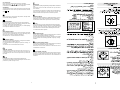
INSTRUCTIONS FOR USE OF CONTROL DEVICES
(ACCORDING TO THE MODELS)
Fig. 17
Fig. 18
Setting
To set, press and release the desired function, and within 5
seconds set the time with + and - buttons.
+ and - buttons.
The + and - buttons increase or decrease the time at a speed
depending on how long the button is pressed.
Setting the time
Press any two buttons (cooking time, end time, minutes counter)
at the same time, and + or - button to set the desired time. This
deletes any previously set programme. The contacts are switched
off and the AUTO symbol flashes.
Manual use
By pressing the manual button the relay contacts switch on, the
AUTO symbol switches off and the saucepan symbol lights up.
Manual operation can only be enabled after the automatic
programme is over or it has been cancelled.
Automatic use
Press the cooking time or end time button to switch automatically
from the manual to the automatic function.
Semi-automatic use with cooking time setting
Press the cooking time button and set the desired time with + or
-. The AUTO and cooking time symbols light up continuously. The
relay switches on immediately. When the cooking end time
corresponds to the time of day, the relay and cooking time symbol
switch off, the sound signal rings and the AUTO symbol flashes.
Semi-automatic use with end time setting
Press the end time button. The time of day appears on the display.
Set the cooking end time with + button. The AUTO and cooking
time symbols light up continuously. The relay contacts switch on.
When the cooking end time corresponds to the time of day, the
relay and the cooking time symbol switch off. When the cooking
time is up, the AUTO symbol flashes, the sound signal rings and
both the relay and the cooking time button switch off.
Automatic use with cooking time and end time setting
Press the cooking time button and select the length of the cooking
time with + or - button. The AUTO and cooking time symbols light
up continuously. The relay switches on. By pressing the cooking
Minute timer
Cooking time
Cooking end
Manual
Subtract time
Add time
9
0
60
30
10
20
40
50
70
100
110
90
80
120
stop
10
15
20
25
30
35
40
45
50
55
5
0
MINUTES COUNTERS (Fig.17)
Turn the knob clockwise to set the desired cooking time.
The minutes minder can be adjusted from 1 to 60 minutes.
A sound signal will inform you that the chosen time is up.
PROGRAMMER WITH COOKING END TIME (Fig.18)
For a manual operation of the programmer, turn the knob
anticlockwise to
.
Adjust the cooking time by turning the knob clockwise.
Select the cooking time with the relevant knob (max.120 min.).
The oven will switch off automatically when the cooking is up.
MECHANICAL PROGRAMMER WITH COOKING START/END TIME
Setting the clock: press knob B and turn it anti-clockwise.
Adjustment of starting time: press
knob A and turn it anti-clockwise.
Adjustment of connection time:
turn knob B anti-clockwise without
pressing it in.
The end of the connection is
announced by an alarm bell, which
can be stopped by turning knob B to
position 0 without pressing
it in. Manual connection: turn knob B
to position I a without pressing it in.
O
B
A
III
II
XI
XII
X
IX
VIII
VI
V
VI
I
V
II
PCI "Campanil"TR 259 Analogic
Setting the clock
Press the control knob and turn
clockwise.
Alarm programme adjustement
Turn the knob clockwise without
pressing it in. At the end of the
programmed time an alarm will
sound.
To cancel it, turn the knob to the
bell.
XII
XI
X
IX
VIII
VII
VI
V
I
II
III
IV
“LED” PROGRAMMER (Fig. 21)
Features
24 hours clock with automatic programme and minutes counter.
Functions
Cooking time, cooking end time, manual position, clock,
minutes counter, times to be set up to 23 hours 59 minutes.
Display
4-figures, 7-segments diplay for cooking times and time of day.
Cooking time and manual function = saucepan symbol
Automatic function = AUTO
Minutes counter = bell symbol
The symbols light up when the corresponding functions are
selected.
Fig. 21
A
U
T
O

10
end time button the next cooking end time appears on the display.
Set the cooking end time with + button. The relay and the cooking
time symbol switch off.
The symbol lights up again when the time of day corresponds to
the cooking start time. When the cooking time is up, the AUTO
symbol flashes, the sound signal rings, the cooking time symbol
and the relay switch off.
Minutes counter
Press the minutes counter button and set the cooking time with
+ or - button.
The bell symbol lights up when the minutes counter is operating.
When the set time is up, the sound signal rings and the bell symbol
switches off.
Sound signal
The sound signal starts at the end of a programme or of the
minutes counter function and it lasts for 15 minutes.
To stop it, push any one of the functions buttons.
Start programme and check
The programme starts 4 seconds after it has been set.
The programme can be checked at any time by pressing the
corresponding button.
Setting error
A setting error is made if the time of day on the clock falls within
the cooking start and end times.
To correct the setting error, change the cooking time or cooking
end time.
The relays switch off when a setting error is made.
Cancelling a setting
To cancel a setting, press the cooking time button and then press
the - button until 00 00 appears on the display.
A set programme will automatically cancel on completion.
ELECTRONIC TIMER FOR COOKER (Fig. 23)
Functions
On
The display flashes.
Time setting
Press the left button.
Set the time with buttons “+” and “-”.
This function remains activated 7 seconds after the last +/-
operation.
Timer setting
This function is permanently activated and it will be immediately
set with +/- buttons.
During setting the units are 10 seconds.
During count down the timer takes priority on the display.
The units are seconds.
The maximum time is 99 minutes.
The relay contact (when available) is closed during the count down
only.
Reset timer
Press “+” and “-” buttons together and release “+” button first.
Signal
The signal after time out will stay 7 minutes if it has not been reset
with the “+” button (one touch only).
Signal frequency
When the display shows the time of day, the signal frequency can
be selected by pressing the “-” button. Three different frequencies
are selectable.
1 Time of the day
2 Timing and insertion
3 Signal timing and
insertion
Fig. 23
COOKING PROGRAMMER WITH SOUND SIGNAL
HP33 STANDARD (Fig. 24)
1 - Clock (knob 2)
- Set the exact time of day by pulling and turning knob 2
clockwise.
2 - Cooking time (knob 1, window D)
- Set the cooking time on window D by turning knob 1 clockwise.
- When the set time is up, a sound signal rings.
- Stop it by turning knob 1 clockwise until symbol “0” appears
on window D.
3 – Set start of cooking (knob 2, index C, dial E)
- Turn knob 2 clockwise (without pulling it) until index C is lined
up with the start cooking time on dial E.
A - Manual use (no selection)
- Make sure index C is lined up with the 12 on dial A.
- To switch the oven on, turn knob 1 clockwise until symbol “I”
appears on window D.
- To switch the oven off, turn knob 1 anticlockwise until symbol
“0” appears on window D.
B - Semi-automatic use
Cooking starts immediately and stops automatically when the set
time is up.
- Make sure index C is lined up with the 12 on dial A.
- Set the cooking time on window D.
C - Automatic use
The cooking start is delayed at the time set with index C. The
oven switches off automatically when the time is up.
- Keep index C on the desired start time to select it on dial E.
- Set the cooking time on window D.
10
1
1
9
12
I
0
10
1
1
1
9
12
110
10
1
1
1
9
12
110
6
3
10
1
1
1
2
3
5
6
7
9
4
12
0
F
D
C
A
B
E
2
1

11
CARE AND MAINTENANCE
Before cleaning the appliance
, disconnect the gas general
tap and unplug the appliance or disconnect power at the main
circuit breaker of the electrical system
.
Do not clean the appliance surfaces when still hot.
ENAMELLED SURFACES
Clean with a damp sponge using soap and water.
Grease can be easily removed using hot water or a specific
cleansing agent for enamelled surfaces. Do not use abrasive
cleansers.
Do not leave any acid or alkaline substances (lemon juice, vinegar,
salt, etc.) on the enamel.
Clean the parts in stainless steel with specific cleansers for stainless
steel surfaces.
These detergents must be applied using a soft cloth.
GRIDS AND BURNERS
To clean the work-top burners, remove them by pulling upwards
and soak them for about 10 minutes in hot water with a little
detergent. After having cleaned and washed them, wipe them
carefully.
Make sure that no burner hole is clogged.
Clean the burners once a week or more frequently if necessary.
MAKE SURE YOU HAVE ASSEMBLED THE BURNERS IN A
RIGHT WAY.
GLASS-CERAMIC SURFACE
To clean the work-top, you must follow the same precautions you
use to clean the glasses of your house. Soft stains caused by
aluminium pans bottoms can be removed by means of vinegar.
Make sure that sugar does not fall on the work-top during cooking,
if it falls disconnect the relevant hotplate, and clean as soon as
possible with hot water, before it gets cold.
In case there are stains of burnt sugar or similars after cooking,
clean them using a spatule or a razor before the cooking zone
becomes cold (see picture).
A
BC
Fig. 25
ELECTRIC HOTPLATES
After use, for a good conservation, the hotplate must be slighty
greased by means of a cloth soaked with oil, so that the surface
remains always clean and bright.
This avoids the eventual formation of rust too.
INSIDE OVEN GLASS
For some models, the inside glass of the oven door can be
disassembled for an easy cleaning.
In order to disassemble it, unscrew screws B as shown in the
picture.
Fig. 26
OVEN DOOR
For some models, the oven door can be disassembled in the
following way:
hinges A are provided, for this purpose, with two movable jumpers
B; these, once hooked to the hinges slots C, when the door is
completely opened, block them. After that lift the door outward
carring out the two movements shown in the picture. To do that,
operate on the door sides next to the hinges. In order to re-
assemble the door, introduce the hinges in their relevant slots.
Before closing the door, do not forget to remove the movable
jumpers B.
Attention, in proximity of the oven door hinges, there is hurt danger.
Fig. 27
OVEN
Clean the enamelled parts with a damp sponge using soap and
water. Grease can be easily removed using hot water or a specific
cleansing agent for enamelled surfaces.
Do not use abrasive cleansers.
SELF-CLEANING OVEN
In some models particular porosity of the oven inside sides enable
to absorb part of the grease, reducing it to little fragments which
can be easily removed.
Make sure that these porosities are never stopped up by big
quantities of overflowing liquids. In this case, clean the part as
soon as the temperature goes down, using specific oven cleansers.
In case of grease stains, clean the oven sides as follows:
let the empty oven operate at max. temperature for about 30
minutes, let it cool down, then clean the sides by means of a damp
cloth.
For some appliances, the self-cleaning side panels and the shelves
frame can be removed.
The shelves holder frame is hooked on to three catches. Simply
press the catches down slightly to remove the frame (Fig. 28A),
and this will also release the self-cleaning side panel (Fig. 28B).
To remove the rear self-cleaning panel (which also acts as the fan
guard), refer to Fig. 28C.
Fig. 28
AB
C

12
230 V ~ 400 V 2N~ 400 V 3N~
5
4
3
2
1
L1
N
E
5
4
3
2
1
L1
L2
N
E
5
4
3
2
1
L1
L2
L3
N
E
ROOMS VENTILATION
GAS CONNECTION
INSTRUCTIONS DESTINED TO THE USER
SECOND PART
Fig. 29
OVERALL DIMENSIONS
The cooker is fitted with 4 legs for an eventual alignment in height
with the furniture.
WARNINGS
Before performing any repair or operation
, switch the appliance
off and close the gas tap
. The qualified engineer is responsible
for correct installation according to the safety standards in
force.
The earthing of the appliance is legally binding.
The manufacturer declines all responsibility for any damage to
persons, animals or things caused by failure to observe the above
mentioned rules.
The technical data are indicated on the data nameplate placed
on the rear of the appliance.
The adjustment conditions are stated on the label applied on the
packaging and on the appliance.
Do not use the oven door handle to move the appliance, such as
to remove it from the packaging.
The appliance is in class 1 or class 2 subclass 1.
For the electric the appliance is in class Y.
INSTALLATION
IMPORTANT: The coating of the furniture must be able to withstand
high temperatures (min. 90°C).
If the appliance is to be installed near units, leave the minimum
gaps specified in the table below.
REG. MAX 15mm
Fig. 31
Fig. 30
min. 20mm
min.100 mm
min. 50 mm min. 50 mm
min. 650 mm
min. 400 mm
min. 20mm
595
1430
600
850
GAS APPLIANCES
This appliance is not connected to a device to vent the combustion
products. It must therefore be installed and connected in conformity
with the installation standards in force.
Particular attention must be paid to the standards on ventilation
of the room.
VENTILATION OF ROOMS
Remember that this appliance can be installed and work in well-
ventilated rooms only, according to the standards in force, such
as to allow, with openings on the external walls or with special
ducts, a correct natural or forced ventilation ensuring permanently
and sufficiently both the entry of the air needed for correct
combustion and the removal of spent air.
In particular when there is only this gas appliance in the room,
there must be a hood over the appliance to ensure the natural
and direct removal of spent air, with a vertical straight duct of
length equal to at least twice the diameter and a minimum section
of at least 100 cm
2
.
For the indispensable entry of fresh air into the room there must
be a similar 100 cm
2
opening directly to the outside, situated at
a height near floor level so that it is not blocked either inside or
outside the wall and so as not to cause disturbances to correct
burners combustion and to the regular removal of spent air and
with a difference of height with respect to the outlet opening of at
least 180 cm.
Remember that the quantity of air necessary for combustion must
never be less than 2m
3
/h for each kW of power (see total power
in kW on the appliance data plate).
In all other cases, i.e. when there are other gas appliances in the
same room, or when natural direct ventilation is not possible and
natural indirect or forced ventilation must be installed, contact a
qualified specialist who will install and make the ventilation system,
scrupulously observing the regulations contained in the standards
in force.
The openings must be so positioned that there are no draughts
of air which cannot be tolerated by the occupants.
Moreover to eliminate combustion products, it is forbidden to use
flues already used by other appliances.
We recommend to check wether the appliance has been foreseen
for the kind of gas distributed.
The appliance must be connected to the gas piping in a workmanlike
way and in conformity with the regulations in force which lay down
the installation of a safety valve at the end of the piping.
For butane and propane a pressure reducer conforming to the
standards in force may perform this task.
min. 100cm
2
.
electric fan
min. 180 cm.
min. 100cm
2
.
min. 180 cm.
Fig. 33

13
ELECTRICAL CONNECTION
Connection of the appliance to the power mains should be done
by a licensed electrician familiar with local safety regulations.
This appliance must be earthed by law. Before connecting
the appliance to the electrical supply, check that the earth
system in your house is working correctly.
Check that unit voltage and power, marked on the rating plate
applied on the appliance, are correct for the supply. It is necessary
that the feeding network is protected by a powerful switch able to
disconnect completely the network with a contacts separation of
at least 3 mm. Be sure that the earth wire green/yellow is not
interrupted by the switch.
Important: The wires in the mains lead are so coloured:
- green/yellow = earth " "
- blue = neutral “N”
- brown = live “L”
The wire coloured green/yellow must be connected to the terminal
in the plug which is marked with letter 'E' or by the earth symbol
or coloured green or green/yellow. The wire coloured blue must
be connected to the terminal which is marked with letter 'N' or
coloured black. The wire coloured brown must be connected to
the terminal which is marked with letter 'L' or coloured red. The
supply cable must not come into contact with any component the
temperature of which exceeds the ambient temperature by 50°C.
If a plug is used for connection, the plug to be connected to the
supply cable and the socket to which it is connected must be of
the same type (conforming to the standards). Easy access to the
plug or the switch is ensured once the appliance is installed. Ensure
that there is sufficient cable allowed for any subsequent removal
of the unit. If the plug is non-rewireable, pay attention to the
following points: the plug must never be cut by the supply cord.
There is shock hazard when this plug is inserted in a socket-outlet
elsewhere in the house. Never use the plug without the fuse cover
fitted. Referring to the pertinent spare parts, apply to the appliance's
supplier. The manufacturer declines all responsibility for any
damage to persons or things caused by failure to observe
the rules indicated above.
Some models with single-phase supply can be supplied from a
three phase source by performing the following.
Move the connection U bolts depending on the type of supply (see
table below).
Connect the supply cable of appropriate section:
230 V ~ 400 V 2N~ 400 V 3N~
5
4
3
2
1
L1
N
E
5
4
3
2
1
L1
L2
N
E
5
4
3
2
1
L1
L2
L3
N
E
Fig. 38
NB: Keeping into consideration the simultaneity coefficient of 0,75
BACK SIDE
Fig. 36
170
Inflexible tube entry
A
Flexible tube entry
The seal gaskets must be in accordance with rules.
Once the gas appliance has been connected, check the connection
seal by means of soapy water.
The end of the attachment is threaded.
The possible connections are:
Fig. 34
1/2”
- by rigid pipe in iron or copper
- by flexible tube in stainless steel with continuing wall, with
mechanical connection in accordance with rules. The tube must
be directly connected to the manifold elbow (see Fig.34).
- by the insertion of a rubber tube in accordance with rules.
This tube must be connected directly on the push-on connector,
concerning the gas used, and it must be blocked with a band.
In the last case, check the tube's printed date of expiry and
replace it before this date.
WARNINGS
Concerning rubber flexible tubes (max. length 1500 mm), we
remember you:
1 - to avoid the tube to be narrowed or crushed
2 - do not submit it to traction or torsion efforts
3 - to avoid contact with sharp edges, etc...
4 -to avoid contact with parts reaching temperatures over 70°C
the ambient temperature
5 - to ensure that they can be checked for all their length.
F
F
HOSE
ATTACHMENT
FOR LIQUID
GAS
Fig. 35
If the connecting tube must be passed behind the appliance,
observe the regulations of the picture, making sure in the last case
that the tube is kept in support A.
HOSE
ATTACHMENT
FOR NATURAL
GAS
Type of appliance Single-phase Three-phase connection
connection 230V~ 400V 2N~ 400V 3N~
4 plates Rubber H05 RR-F Rubber H05 RR-F Rubber H05 RRF
Section 3 x 4 mm
2
(*) 4 x 2,5mm
2
(*) 5 x 1,5mm
2
(*)
Appliance type Single-phase supply 230V~
Type of cable Section
All gas Rubber H05 RR-F 3 x 0,75 mm
2
All gas with electric grill Rubber H05 RR-F 3 x 1 mm
2
Alla gas + 1 electric plate Rubber H05 RR-F 3 x 1 mm
2
Alla gas + 2 electric plate Rubber H05 RR-F 3 x 1,5 mm
2
All gas with electric oven Rubber H05 RR-F 3 x 1,5 mm
2
All gas with electric oven + 1 plate Rubber H05 RR-F 3 x 1,5 mm
2
All gas with electric oven + 2 plate Rubber H05 RR-F 3 x 2,5 mm
2

14
Z
T
If the appliance is foreseen to operate with a type of gas different
from the suitable supply gas, proceed as follows: change the
injectors, adjust the minimum flow of the burners, change the
push-on connector.
In order to change the work-top injectors, it is necessary to act as
follows: remove the grids, remove burners and flame-spreaders
(see fig.A), change the injector (see fig.B) and replace it with
another one suitable for the new type of gas (see table D). Re-
assemble everything in the opposite direction, paying attention to
place the flame-spreader in the right way on the burner.
To change the oven injector, it is necessary to act as follows: open
the oven door, remove the lower side of the oven (see fig.C),
unscrew screw C and disassemble the oven burner (see fig.D).
Change the injector (see fig.E) and replace it with another one
suitable for the new gas type (see table D).
Re-assemble everything in the opposite direction, paying attention
to place the burner in the right way on its rear slot.
A
DC
E
Fig. 41
C
GAS ADJUSTMENT
Fig. 39
DA
EC
BC
DA
HOB
4 BURNERS 3 BURNERS
1 EL. PLATE
E = Ø145mm
1000 ÷ 1500W
To change the grill injector, it is necessary to act as follows: open
the oven door, unscrew screw C and disassemble the grill burner
(see fig.F). Change the injector (see fig.G) and replace it with
another one suitable for the new gas type (see table D).
Re-assemble everything in the opposite direction, paying attention
to place the burner in the right way on its rear slot.
B
Fig. 42
F
G
C
Fig. 43 Fig. 44
MINIMUM FLOW ADJUSTMENT FOR WORK-TOP TAPS
In order to adjust the minimum, act as follows: switch the burner
on, and turn the knob towards the minimum flow position
.
Remove the knob from the tap, introduce a little screwdriver in the
tap rod (fig. 43).
Attention: in taps with security valve, the minimum adjusting screw
“Z” is placed outside the rod tap (fig. 44).
Fig. 45 Fig. 46
Unscrew the adjusting screw in order to increase the flow or screw
it to decrease the flow.
The right adjustment is obtained when the flame has a length of
about 3 or 4 mm.
For butane/propane gas, the adjusting screw must be tight screwed.
Make sure that the flame does not go out passing quickly from
the max. flow
to the minimum flow and viceversa .
Assemble the knob again.
MINIMUM FLOW ADJUSTMENT FOR OVEN THERMOSTAT
In order to adjust the minimum, act as follows: switch the burner
on turning the knob to the maximum position.
Remove the knob and unscrew of some turns the by-pass screw
(fig. 45).
Assemble the knob and let the oven warm up for 15 minutes; after
that turn the knob to the minimum position.
After having removed the knob once again, making sure that the
thermostat rod has not been moved, screw slightly the above
mentioned by-pass screw, to obtain a flame of 3 or 4 mm of length.
For butane/propane gas, the adjusting screw must be tight screwed.
Make sure that the flame does not extinguish passing quickly from
the maximum flow to the minimum flow, and closing and opening
the oven door (the oven door must be closed softly).
Attention: for taps with safety device, the minimum adjusting screw
“T” is on the outside of the tap rod (fig. 46).
TAB. D GENERAL INJECTORS TABLE
Kind of gas mbar Nozzle Burners Potenza Watt Consumo
N. Posizione-tipo max. min. max.
118 A-Rapide 3000 750 286 l/h
NATURAL 20 97 B,C-Semi rapide 1750 440 167 l/h
72 D-Auxiliary 1000 300 95 l/h
140 A-Triple crown 3500 1500 317 l/h
115 Oven 3100 1000 296 l/h
100 Grill 2100 200 l/h
G.P.L. 30 85 A-Rapide 3000 750 219 g/h
BUTANE 28 65 B,C-Semi rapide 1750 440 128 g/h
PROPANE 37 50 D-Auxiliary 1000 300 73 g/h
94 A-Triple crown 3300 1500 255 g/h
82 Oven 3100 1000 226 g/h
73 Grill 2100 153 g/h

15
Clean the cone and its slot by means of a cloth soaked with diluent.
Slightly grease the cone with the relevant grease, put it in its slot,
and turn it some times. Remove the cone again, remove the
exceeding grease making sure the gas entries are not obstructed
by grease residuals. Assemble everything carefully in the opposite
direction check the connection seal by means of soapy water.
TAPS REPLACEMENT
Act as follows: open the work-top and disassemble also the control
panel as described on the previous paragraph. Unscrew screw
nut D of the gas tube supplying the burner. Unscrew screw V fixing
the tap to the bridle and remove it (see picture).
Note: Every time the tap is replaced, it is necessary to replace the
seal gasket too check the connection seal by means of soapy
water.
1
5
7
Fig. 51
D
V
GAS OVEN WITH WATT
GRILL HEATING ELEMENT 2000
N.B.: the rapid electric plates are marked with a red dot.
ELECTRIC PLATE Ø mm WATT
STANDARD (A-C) 145 1000
RAPID (D) 180 2000
STANDARD (E) 180 1500
AIR FORCED OVEN WATT
GRILL ELEMENT 2000
FANNED ELEMENT 2100
MULTIFUNCIONAL OVEN WATT
UPPER ELEMENT 850
LOWER ELEMENT 1200
GRILL ELEMENT 850+1050
FANNED ELEMENT 2100
CONVENTIONAL OVEN WATT
UPPER ELEMENT 850
LOWER ELEMENT 1200
GRILL ELEMENT 850+1050
APPLIANCE MAINTENANCE
E 14
15 W - 230 V~
T300°C
A
WARNINGS
Before performing any repair or operation,
switch the appliance
off and close the gas tap.
The manufacturer declines all responsibility for any damage to
persons, animals or things caused by failure to observe the rules
indicated above.
The oven lamp used is of a special type withstanding high
temperatures. To replace it, act as follows: disassemble the
protecting glass (A) and replace the burnt lamp with one of the
same type. Reassemble the protecting glass.
DISASSEMBLE OF WORK-TOP
In case it is necessary to repair or replace the inside components,
act as follows:
Remove the grids, remove burners and flame-spreaders (see
fig. 47), unscrew the visible screws “V” placed on the work-top
(see fig. 48). Disassemble the work-top by unscrewing the 4 rear
screws “A” (see fig. 49). In this way it is possible to lift the work-
top and to reach the inside components.
Fig. 46 bis
Fig. 48
V
Fig. 49
A
Fig. 47
- To disassemble the control panel, unscrew the 3 internal screws
fixing the control panel to the oven face.
GREASING OF TAPS
If a tap becomes hard to be turned, grease it using a specific
grease withstanding high temperatures. Act as follows: open the
work-top and disassemble also the control panel as described on
the previous paragraph. Unscrew the two fixing screws from the
burner body (see picture) and remove the cone.
Fig. 50
D-E
A
D-E

16
EC
DA
24
31
Fig. 52
Fig. 53
AREA FOR CERAMIC HOB Ø mm WATT
HALOGEN (1-2) 200 1700
or RADIANT 1800
RADIANT (4) 230 1700
or RADIANT 2100
RADIANT (3) 165 1200
Fig. 55
Fig. 54
D-E
A
D-E
-
 1
1
-
 2
2
-
 3
3
-
 4
4
-
 5
5
-
 6
6
-
 7
7
-
 8
8
-
 9
9
-
 10
10
-
 11
11
-
 12
12
-
 13
13
-
 14
14
-
 15
15
-
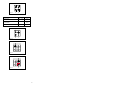 16
16


AEG ZW6640I User manual
- Category
- Kitchen & houseware accessories
- Type
- User manual
Ask a question and I''ll find the answer in the document
Finding information in a document is now easier with AI
Related papers
Other documents
-
Zanussi ZCG9001X User manual
-
Electrolux ZCG9001X User manual
-
-
LADEN C 339 BR Program Chart
-
-
AEG Electrolux EKM10420X User manual
-
-
Frigidaire FNKA90HNPS User manual
-
Scholtes CP 956 G Instructions for Use and Installation
-
Technika TGG96U User manual