
DW45RN
Roofing Coil Nailer
Cloueuse Pour Toiture À Clous En Bobine
Clavadora Para Techado A Resorte
INSTRUCTION MANUAL
GUIDE D’UTILISATION
MANUAL DE INSTRUCCIONES
INSTRUCTIVO DE OPERACIÓN, CENTROS DE SERVICIO Y PÓLIZA DE
GARANTÍA. ADVERTENCIA: LÉASE ESTE INSTRUCTIVO ANTES DE
USAR EL PRODUCTO.
If you have questions or comments, contact us.
Pour toute question ou tout commentaire, nous contacter.
Si tiene dudas o comentarios, contáctenos.
1-800-4-D
e
WALT • www.dewalt.com
Page Size: 8.5 x 5.5"
Page is loading ...

BEFORE OPERATING THIS TOOL, CAREFULLY READ AND
UNDERSTAND ALL INSTRUCTIONS IN THE IMPORTANT
SAFETY INSTRUCTIONS SECTION.
Definitions: Safety Guidelines
The definitions below describe the level of severity for each
signal word. Please read the manual and pay attention to these
symbols.
DANGER: Indicates an imminently hazardous situation
which, if not avoided, will result in death or serious injury.
WARNING: Indicates a potentially hazardous situation which,
if not avoided, could result in death or serious injury.
CAUTION: Indicates a potentially hazardous situation which,
if not avoided, may result in minor or moderate injury.
NOTICE: Indicates a practice not related to personal injury
which, if not avoided, may result in property damage.
IF YOU HAVE ANY QUESTIONS OR COMMENTS ABOUT THIS OR
ANY D
e
WALT TOOL, CALL US TOLL FREE AT: 1-800-4-D
e
WALT
(1-800-433-9258)
SAVE ALL WARNINGS AND INSTRUCTIONS
FOR FUTURE REFERENCE
Important Safety Instructions
WARNING: Do not operate this unit until you read this instruction
manual for safety, operation and maintenance instructions.
WARNING: This product contains chemicals known to the State
of California to cause cancer, and birth defects or other reproductive
harm. Wash hands after handling.
WARNING: Some dust contains chemicals known to the State of
California to cause cancer, birth defects or other reproductive harm such
as asbestos and lead in lead based paint.
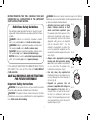
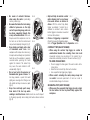
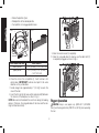
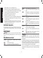
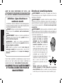
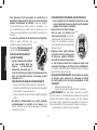
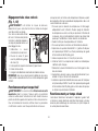
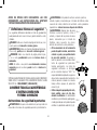
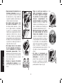
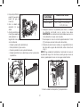
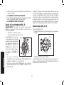
• Actuating tool may result in flying
FIG. A
FIG. B
FIG. C
FIG. D
debris, collation material, or dust
which could harm operator’s eyes.
The operator and all those persons in the
general area should wear safety glasses
with permanently attached side shields.
Approved safety glasses are imprinted
with the characters “Z87.1”. It is the
employer’s responsibility to enforce the
use of eye protection equipment by the
tool operator and other people in the work
area. (Fig. A)
• Always wear appropriate personal
hearing and other protection during
use. Under some conditions and duration
of use, noise from this product may
contribute to hearing loss. (Fig. A)
• Use only clean, dry, regulated air.
Conden sation from an air compressor can
rust and damage the internal workings of
the tool. (Fig. B)
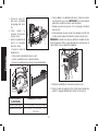
• Regulate air pressure. Use air
pressure compatible with ratings on
the nameplate of the tool. (Not to
exceed 120 psi, 8.3 bar) Do not connect
the tool to a compressor rated at over
200 psi. The tool operating pressure must
never exceed 200 psi even in the event of
regulator failure. (Fig. C)
English
1

• Only use air hose that is rated for a maximum working
pressure of at least 150 PSI (10.3 BAR) or 150% of the
maximum system pressure, which ever is greater. (Fig. D)
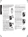
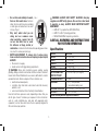
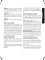
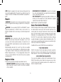
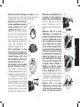
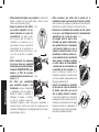
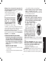
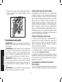
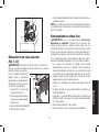
• Do not use bottled gases to power this
FIG. E
FIG. F
FIG. G
tool. Bottled compressed gases such as
oxygen, carbon dioxide, nitrogen,
hydrogen, propane, acetylene or air are
not for use with pneumatic tools. Never
use combustible gases or any other
reactive gas as a power source for this
tool. Danger of explosion and/or serious
personal injury may result. (Fig. E)
• Use couplings that relieve all
pressure from the tool when it is
disconnected from the power supply.
Use hose connectors that shut off air
supply from compressor when the tool is
disconnected. (Fig. F)
• Disconnect tool from air supply
when not in use. Always disconnect
tool from air supply and remove
fasteners from magazine before
leaving the area or passing the tool
to another operator. Do not carry
tool to another work area in which
changing location involves the use
of scaffoldings, stairs, ladders, and
the like, with air supply connected.
Do not make adjustments, remove magazine, perform
maintenance or clear jammed fasteners while connected
to the air supply. If the contact trip is adjusted when the tool
is connected to the air supply and nails are loaded, accidental
discharge may occur. (Fig. G)
• Connect tool to air supply before loading fasteners, to
prevent a fastener from being fired during connection. The
tool driving mechanism may cycle when tool is connected to
the air supply. Do not load fasteners with trigger or contact trip
depressed, to prevent unintentional firing of a fastener.
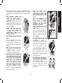
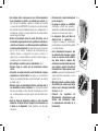
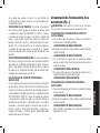
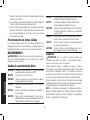
• Do not remove, tamper with, or
otherwise cause the tool, trigger, or
contact trip to become inoperable. Do
not tape or tie trigger or contact trip in the
ON position. Do not remove spring from
contact trip. Make daily inspections for
free movement of trigger and contact trip.
Uncontrolled discharge could result.
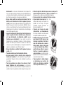
• Inspect tool before use. Do not
operate a tool if any portion of the tool,
trigger, or contact trip is inoperable,
disconnected, altered, or not working
properly. A tool that is not in proper
working order must not be used. Tags
and physical segregation shall be used
for control. Leaking air, damaged parts
or missing parts should be repaired or
replaced before use. (Fig.H)
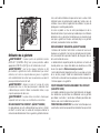
• Do not alter or modify the tool in any
way. (Fig. I)
• Always assume that the tool contains
fasteners.
FIG. H
FIG. I
FIG. J
English
2

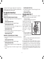
• Do not point the tool at co-workers or yourself at any time.
No horseplay! Work safe! Respect the tool as a working implement.
(Fig. J)
• Keep bystanders, children, and
visitors away while operating a
power tool. Distractions can cause you
to lose control. When tool is not in use, it
should be locked in a safe place, out of
the reach of children.
• Remove finger from trigger when
not driving fasteners. Never carry
tool with finger on trigger. Accidental
discharge could result.
• Do not lift, pull or lower tool by the
hose.
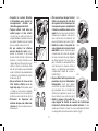
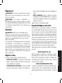
• Do not overreach. Maintain proper
footing and balance at all times. Loss of
balance may cause cause personal injury.
(Fig. K)
• Make sure hose is free of obstructions
or snags. Entangled or snarled hoses
can cause loss of balance or footing.
• Use the tool only for its intended use.
Do not discharge fasteners into open
air, concrete, stone, extremely hard
woods, knots or any material too
hard for the fastener to penetrate.
Do not use the body of the tool or
top cap as a hammer. Discharged
fasteners may follow unexpected path
and cause injury. (Fig. L)
• Always keep fingers clear of
contact trip to prevent injury
from inadvertent release of nails.
(Fig.M)
• Refer to the Maintenance and
Repairs sections for detailed
information on the proper
maintenance of the tool
• Always operate the tool in a clean,
lighted area. Be sure the work
surface is clear of any debris and
be careful not to lose footing when
working in elevated environments
such as rooftops.
• Do not drive fasteners near edge
of material. The workpiece may
split causing the fastener to ricochet,
injuring you or a co-worker. Be aware
that the nail may follow the grain
of the wood (shiner), causing it to
protrude unexpectedly from the side
of the work material. Drive the nail
perpendicular to the grain to reduce
risk of injury. (Fig. N)
• Do not drive nails onto the heads
of other fasteners or with the tool
at too steep an angle. Personal
injury from strong recoil, jammed
fasteners, or ricocheted nails may
result. (Fig. O)
FIG. K
FIG. L
FIG. M
FIG. N
FIG. O
FIG. P
English
3

• Be aware of material thickness
when using the nailer. A protruding
nail may cause injury.
• Be aware that when the tool is being
utilized at pressures on the high
end of its operating range, nails can
be driven completely through thin
or very soft work material. Make sure
the pressure in the compressor is set so
that nails are set into the material and
not pushed completely through. (Fig. P)
• Keep hands and body parts clear
of immediate work area. Hold
workpiece with clamps when necessary
to keep hands and body out of potential
harm. Be sure the workpiece is properly
secured before pressing the nailer
against the material. The contact trip
may cause the work material to shift
unexpectedly. (Fig.Q)
• Do not use tool in the presence of
flammable dust, gases or fumes. The
tool may produce a spark that could
ignite gases causing a fire. Driving a nail
into another nail may also cause a spark.
(Fig.R)
• Keep face and body parts away
from back of the tool cap when
working in restricted areas. Sudden recoil can result in impact
to the body, especially when nailing into hard or dense material.
(Fig. S)
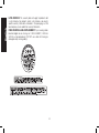
• Grip tool firmly to maintain control
while allowing tool to recoil away
from work surface as fastener is
driven. With the contact trip (black)
trigger assembled, if contact trip is
allowed to recontact work surface
before trigger is released an unwanted
fastener will be driven.
• Choice of triggering is important.
Check the manual for triggering options.
Refer to Trigger Operation under the Operation section.
CONTRACT TRIP (BLACK TRIGGER)
• When using the contract trip trigger, be careful of
unin tentional double fires resulting from tool recoil.
Unwanted fasteners may be driven if the contact trip is
allowed to accidentally re-contact the work surface. (Fig. T)
TO AVOID DOUBLE FIRES:
• Do not engage the tool against the work surface with a
strong force.
• Allow the tool to recoil fully after each actuation.
• Use sequential trip trigger (gray trigger).
•
When contact actuating the nailer, always keep tool
in control. Inaccurate placement of tool can result in
misdirected discharge of a fastener.
SEQUENTIAL TRIP (GRAY TRIGGER)
• When using the sequential trip trigger, do not actuate
the tool unless the tool is placed firmly against the
workpiece.
FIG. Q
FIG. R
FIG. S
FIG. T
English
4

• Do not drive nails blindly into walls,
FIG. U
floors or other work areas. Fasteners
driven into live electrical wires, plumbing,
or other types of obstructions can result
in injury. (Fig.U)
• Stay alert, watch what you are
doing and use common sense
when operating a power tool. Do
not use tool while tired or under
the influence of drugs, alcohol, or
medication. A moment of inattention while operating power tools
may result in serious personal injury.
• DEPTH ADJUSTMENT: To reduce risk of serious injury
from accidental actuation when attempting to adjust depth,
ALWAYS:
• Disconnect air supply.
• Avoid contact with trigger during adjustments.
WARNING: Some dust created by power sanding, sawing,
grinding, drilling, and other construction activities contains chemicals
known to the State of California to cause cancer, birth defects or other
reproductive harm. Some examples of these chemicals are:
• lead from lead-based paints,
• crystalline silica from bricks and cement and other masonry
products, and
• arsenic and chromium from chemically-treated lumber.
Your risk from these exposures varies, depending on how often you
do this type of work. To reduce your exposure to these chemicals:
work in a well ventilated area, and work with approved safety
equipment, such as those dust masks that are specially designed to
filter out microscopic particles.
WARNING: ALWAYS USE SAFETY GLASSES. Everyday
eyeglasses are NOT safety glasses. Also use face or dust mask
if operation is dusty. ALWAYS WEAR CERTIFIED SAFETY
EQUIPMENT:
• ANSI Z87.1 eye protection (CAN/CSA/Z94.3),
• ANSI S12.6 (S3.19) hearing protection,
• NIOSH/OSHA/MSHA respiratory protection.
SAVE ALL WARNINGS AND INSTRUCTIONS
FOR FUTURE REFERENCE
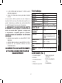
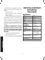
Specifications
MODEL DW45RN
HEIGHT 9.8" (249mm)
WIDTH 5" (127 mm)
LENGTH 11" (280mm)
WEIGHT 5.2 lb (2.4 kg)
OPERATING PRESSURE
70 – 120 psig (4.9 – 8.43kg/cm
2
)
AIR CONSUMPTION
PER 100 CYCLES *
3.7 cfm @ 80 psi (5.62 kg/cm
2
)
LOADING CAPACITY
120 Nails
FASTENER 0.120" (3mm) diameter,
15º wire collated roofing nails
FASTENER LENGTHS 3/4" (19 mm) - 1-3/4" (44.5 mm)
AIR INLET 1/4" NPT (6.4mm)
NOTE: Use only D
e
WALT approved fasteners
English
5

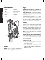
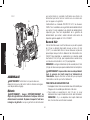
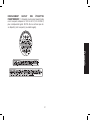
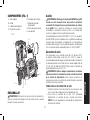
COMPONENTS (FIG. 1)
A. Top cap
B. Trigger
C. Canister cover
D. Door latch
E. Contact trip
F. Depth adjustment wheel
G. Nail guide door
H. Shingle guide
FIG. 1
A
E
F
B
C
H
D
G
ASSEMBLY
WARNING: Disconnect air line from tool and remove fasteners
from magazine before making adjustments or personal injury may
result.
Trigger
WARNING: Keep fingers AWAY from the trigger when not
driving fasteners to avoid accidental actuation. Never carry a
tool with finger on the trigger. With the contact trip trigger (black)
assembled, the tool will drive a fastener if the contact trip is bumped
while the trigger is depressed.
In accordance with the ANSI Standard SNT-101-2015, the D
e
WALT
coil nailers are assembled with a black contract trip trigger. However,
a gray sequential trip trigger kit is available. For a replacement trigger
contact your authorized service center or call 1-800-4-D
e
WALT.
Air Fitting
This tool uses a 1/4" N.P.T. male plug. The inside diameter should be
0.180" (4.6 mm) or larger. The fitting must be capable of discharging
tool air pressure when disconnected from the air supply. A 3/8"
(9.5 mm) male quick connector coupling is available from D
e
WALT
and may be used when a 1/4" (6.4mm) supply line is not available.
NOTE: A 3/8" (9.5 mm) supply line (and fittings) are required for
maximum tool performance.
WARNING: Always use couplings that relieve all pressure
from the tool when it is disconnected from the power supply.
Always use hose connectors that shut off air supply from compressor
when the tool is disconnected.
TO INSTALL AN AIR FITTING
1. Wrap the male end of the fitting with thread seal tape prior to
assembly to eliminate air leaks.
2. To install a 1/4" (6.4mm) fitting: screw it directly into the air inlet
and tighten firmly. NOTE: If an adapter is in the air inlet, remove it
prior to inserting the fitting.
English
6

3. To install a 3/8" (9.5 mm) fitting: screw the fitting into the 3/8"
(9.5mm) adapter and then into the air inlet of the tool and tighten
firmly.
OPERATION
Preparing the Tool
WARNING: Read the section titled Important Safety Instructions
at the beginning of this manual. Always wear eye and ear protection
when operating this tool. Keep the nailer pointed away from yourself
and others. For safe operation, complete the following procedures
and checks before each use of the nailer.
NOTICE: To reduce the risk of damage to the tool, only use D
e
WALT
pneumatic tool oil or a non-detergent SAE 20 weight oil. Oil with
additives or detergent will damage tool parts.
1. Before you use the nailer, be sure that the compressor tanks
have been properly drained.
2. Lubricate the tool following these directions:
a. Use D
e
WALT pneumatic tool oil or a non-detergent S.A.E. 20
weight oil. DO NOT use detergent oil or additives as they will
damage o-rings and rubber parts.
b. Use a filter-regulator-lubricator in the air line between the
compressor and the tool when possible.
c. If a lubricator is not available, add 5 to 7 drops of oil in the air
fitting a least twice a day or every 4 hours of use.
3. Wear proper eye, hearing and respiratory protection.
4. Ensure canister is empty of all fasteners.
5. Check for smooth and proper operation of contact trip and
pusher assemblies. Do not use tool if either assembly is not
functioning properly. NEVER use a tool that has the contact trip
restrained in the up position.
6. Check air supply. Ensure that air pressure does not exceed
recommended operating limits, refer to Tool Specifications.
7. Keep tool pointed away from yourself and others.
8. Connect air hose.
9. Check for audible leaks around valves and gaskets. Never use a
tool that leaks or has damaged parts.
WARNING: To reduce the risk of personal injury, disconnect tool
from air supply before performing maintenance, clearing a jammed
fastener, leaving work area, moving tool to another location or
handing the tool to another person.
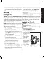
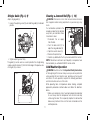
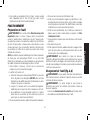
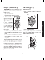
Loading the Tool (Fig. 2–4)
WARNING: Keep the tool pointed away from yourself and others.
Serious personal injury may result.
WARNING: Never load nails with the contact trip or trigger
activated. Personal injury may result.
1. Read all Safety Warnings before using tool.
2. Connect the air supply to the tool.
3. Push the door latch
FIG. 2
D
G
C
(D) to open the nail
guide door (G).
4. Rotate the canister
cover (C) open.
5. Adjust the nail
platform (I) to properly
accommodate the nail
length being used.
• Push the platform
lever (J).
English
7

• Rotate the platform (I) out.
• Slide platform to the desired position.
• Push platform in to engage platform lever.
FIG. 3
J
FIG. 4
I
PLATFORM POSITION NAIL LENGTH
lowest position 1-1/4" (32mm) - 1-3/4" (44.5mm)
upper position 3/4" (19mm) -1-1/4" (32mm)
- 1-3/4" (44.5mm)
6. Place the coil on the nail platform (I). Insert fasteners with
points down. IMPORTANT: Fasteners must point in the same
direction as they will be driven.
7. Uncoil enough nails [approximately 3" (76 mm)] to reach the
nose of the tool.
8. Insert the first nail into the nose and the second nail (M) between
the two rails of the feed pawl as shown in Fig. 5.
NOTE: Be careful not to deform the coil of nails during the loading
process. Otherwise, the nail guide door will not close and the nails
might not feed consistently.
FIG. 5
M
9. Close the canister cover (C) completely.
10. Close the nail guide door (G) making sure the door latch (D)
is completely engaged as shown in Fig. 6.
FIG. 6
D
G
Trigger Operation
WARNING: Always wear proper eye [ANSI Z87.1 (CAN/CSA
Z94.3)] and hearing protection [ANSI S12.6 (S3.19)] when operating
this tool.
English
8

WARNING: The operator must not hold the trigger pulled on
contact trip tools except during fastening operation, as serious injury
could result if the trip accidentally contacted someone or something,
causing the tool to cycle.
WARNING: Keep hands and body away from the discharge area
of the tool. A contact trip tool may bounce from the recoil of driving a
fastener and an unwanted second fastener may be driven, possibly
causing injury.
WARNING: Never use rafter hook to hang tool from body, clothing
or belt.
CONTACT TRIP (BLACK TRIGGER)
The common operating procedure on “Contact Trip” tools is for the
operator to contact the work to actuate the trip mechanism while
keeping the trigger pulled, thus driving a fastener each time the work
is contacted. This will allow rapid fastener placement on many jobs,
such as sheathing, decking and pallet assembly. All pneumatic tools
are subject to recoil when driving fasteners. The tool may bounce,
releasing the trip, and if unintentionally allowed to recontact the work
surface with the trigger still actuated (finger still holding trigger pulled)
an unwanted second fastener will be driven.
SEQUENTIAL TRIP (GRAY TRIGGER)
The Sequential Trip requires the operator to hold the tool against
the work before pulling the trigger. This makes accurate fastener
placement easier, for instance on framing, toe nailing and crating
applications.
The Sequential Trip allows exact fastener location without the
possibility of driving a second fastener on recoil, as described under
Contact Trip.
The Sequential Trip Tool has a positive safety advantage because it
will not accidentally drive a fastener if the tool is contacted against
the work – or anything else – while the operator is holding the trigger
pulled.
CONTACT TRIP OPERATION (BLACK TRIGGER)
When using the contact trip (black) trigger the tool contains a contact
trip that operates in conjunction with the trigger to drive a fastener.
There are two methods of operation to drive fasteners with a contact
trip tool.
SINGLE FASTENER PLACEMENT: To operate the tool in this
manner, first position the contact trip on the work surface, WITHOUT
PULLING THE TRIGGER. Depress the contact trip until the nose
touches the work surface and then pull the trigger to drive a fastener.
Do not press the tool against the work with extra force. Instead, allow
the tool to recoil off the work surface to avoid a second unwanted
fastener. Remove your finger from the trigger after each operation.
RAPID FASTENER OPERATION: To operate the tool in this manner,
hold the tool with the contact trip pointing towards but not touching
the work surface. Pull the trigger and then tap the contact trip against
the work surface using a bouncing motion. Each depression of the
contact trip will cause a fastener to be driven.
SEQUENTIAL TRIP OPERATION (GRAY TRIGGER)
When using the sequential trip (gray) trigger the tool contains a
contact trip that operates in conjunction with the trigger to drive a
fastener. To operate a sequential trip tool, first position the contact
trip on the work surface
WITHOUT PULLING THE TRIGGER. Depress the contact trip and
then pull the trigger to drive a fastener. As long as the contact trip
is contacting the work and is held depressed, the tool will drive a
English
9

fastener each time the trigger is depressed. If the contact trip is
allowed to leave the work surface, the sequence described above
must be repeated to drive another fastener.
Tool Operation Check (Fig.1)
WARNING: Remove all fasteners from tool before performing tool
operation check.
CONTACT TRIP OPERATION (BLACK TRIGGER)
A. With finger off the trigger (A), press the contact trip against the
work surface.
THE TOOL MUST NOT CYCLE.
B. Hold the tool off the work surface, and pull the trigger.
THE TOOL MUST NOT CYCLE.
C. With the tool off the work surface, pull the trigger. Press the
contact trip against the work surface.
THE TOOL MUST CYCLE.
D. Without touching the trigger, press the contact trip against the
work surface, then pull the trigger.
THE TOOL MUST CYCLE.
SEQUENTIAL TRIP OPERATION (GRAY TRIGGER)
A. Press the contact trip against the work surface, without touching
the trigger.
THE TOOL MUST NOT CYCLE.
B. Hold the tool off the work surface and pull the trigger.
THE TOOL MUST NOT CYCLE.
Release the trigger. The trigger must return to the trigger stop on
the frame.
C. Pull the trigger and press the contact trip against the work
surface.
THE TOOL MUST NOT CYCLE.
D. With finger off the trigger, press the contact trip against the work
surface. Pull the trigger.
THE TOOL MUST CYCLE.
Adjusting Depth (Fig. 7)
WARNING: To reduce risk of serious injury from accidental
actuation when attempting to adjust depth, ALWAYS:
• Disconnect air supply.
• Avoid contact with trigger during adjustments.
The depth that the fastener is driven
F
FIG. 7
can be adjusted using the depth
adjustment wheel on the nose of
the tool. The depth of drive is
factory adjusted to a nominal
setting. Test fire a fastener and
check depth. If a change is
desired:
1. To drive the nail deeper, rotate
the depth adjustment wheel
(F) to the right. Setting 5 is the
deepest.
2. To drive a nail shallower, rotate the depth adjustment wheel (F) to
the left. Setting 1 is the shallowest.
Test drive another fastener and check depth. Repeat as necessary
to achieve desired results. The amount of air pressure required will
vary depending on the size of the fastener and the material being
fastened. Experiment with the air pressure setting to determine
the lowest setting that will consistently perform the job at hand. Air
pressure in excess of that required can cause premature wear and/
or damage to the tool.
English
10

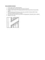
Shingle Guide (Fig. 8, 9)
Adjust shingle guide (H):
1. Loosen the adjusting screw (N) and slide the guide (H) to desired
position.
FIG. 8
H
N
2. Tighten adjusting screw firmly.
The guide (H) can be used as an aid to position the shingle being
nailed a specific distance (O) from the front edge of the previous row
of shingles (Q) as shown.
FIG. 9
H
Q
O
Clearing a Jammed Nail (Fig. 1, 10)
WARNING: Disconnect air line from tool and remove fasteners
from magazine before making adjustments or personal injury may
result..
If a nail becomes jammed in the
FIG. 10
nosepiece, keep the tool pointed
away from you and follow these
instructions to clear:
1. Disconnect the air supply
from the tool.
2. Push the door latch (D) to
open the nail guide door (G)
3. Open the canister cover (C).
4. Remove the jammed nail.
5. Correct any deformation that may have occurred to the nail coil.
NOTE: Should nails continue to jam frequently in nosepiece, have
tool serviced by an authorized D
e
WALT service center.
Cold Weather Operation
WARNING: Read the section titled Important Safety Instructions
at the beginning of this manual. Always wear eye and ear protection
when operating this tool. Keep the nailer pointed away from yourself
and others. For safe operation, complete the following procedures
and checks before each use of the nailer.
When operating tools at temperatures below freezing, complete
preparation procedures outlined above and follow the directions
below.
1. Make sure compressor tanks have been properly drained prior
to use. Always drain the compressor tanks at least once daily
while using the nailer. This is especially important in cold weather
because any moisture in the air in the tanks will condense in the
cold temperature.
English
11

2. Keep the tool as warm as possible prior to use.
3. Make certain all fasteners have been removed from canister.
4. Put 5 to 7 drops of D
e
WALT Pneumatic Tool Oil or winter weight
pneumatic oil containing ethylene glycol in the end cap.
5. Lower air pressure to 80 psi (5.5 bar) or less.
6. Reconnect air and load nails into canister.
7. Actuate the tool 5 or 6 times into scrap lumber to lubricate o-rings.
8. Turn pressure up to operating level (not to exceed 120 psi) and
use tool as normal.
9. Re-lubricate with D
e
WALT Pneumatic Tool Oil or winter weight
pneumatic oil containing ethylene glycol in the end cap at least
twice a day or after 4 hours of use.
Hot Weather Operation
Tool should operate normally. However, keep tool out of direct sunlight
as excessive heat can damage bumpers, o-rings and other rubber
parts.
MAINTENANCE
WARNING: Disconnect air line from tool and remove fasteners
from magazine before making adjustments or personal injury may
result.
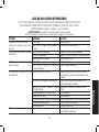
Daily Maintenance Chart
ACTION Lubricate tool with 5-7 drops of D
e
WALT Pneumatic
Tool Oil
WHY Prevents failure of o-rings
HOW Insert drops into air fitting on end cap of tool
ACTION Drain compressor tanks and hoses daily
WHY Prevents accumulation of moisture in compressor and
nailer
HOW Open petcocks or other drain valves on compressor
tanks. Allow any accumulated water to drain from
hoses
ACTION Clean canister, feed piston area and contact trip
mechanism.
WHY Permits smooth operation of magazine, reduces wear
and prevents jams
HOW Blow clean with compressed air. The use of oils or
solvents is not recommended as they tend to attract
debris
ACTION Before each use, check to ensure all screws, nuts and
fasteners are tight and undamaged
WHY Prevents jams, leaks and premature failure of tool
parts
HOW Tighten loose screws or other fasteners using the
appropriate hex wrench or screwdriver
Cleaning
WARNING: DO NOT use gasoline or similar highly flammable
liquids to clean the nailer. Vapor could be ignited by a spark, causing
and explosion.
Tar and dirt may build up on the nose and trip lever preventing correct
operation. Remove any buildup with kerosene, #2 fuel oil or diesel fuel.
Do not dip the nailer into these solvents beyond the height of the nail
heads, to avoid solvent getting into the drive cylinder.
Dry off the nailer before use. Any oil film left after cleanup will
accelerate the tar build up and the nailer will require more frequent
cleaning.
English
12

NOTE: Solvents sprayed on the nose to clean and free up the trip
may have the opposite effect! The solvent may soften the tar on the
shingles and cause tar buildup to be accelerated. Dry operation is
better.
Repairs
WARNING: To reduce the risk of serious personal injury, remove
nails from magazine before making any adjustments or servicing this
tool.
WARNING: To assure product SAFETY and RELIABILITY, repairs
should be performed by a D
e
WALT factory service center or a
D
e
WALT authorized service center. Always use identical replacement
parts.
Accessories
WARNING: Since accessories, other than those offered by
DEWALT, have not been tested with this product, use of such
accessories with this tool could be hazardous. To reduce the risk of
injury, only DEWALT, recommended accessories should be used with
this product.
Recommended accessories for use with your tool are available
at extra cost from your local dealer or authorized service center.
If you need assistance in locating any accessory, please contact
DEWALT Industrial Tool Co., 701 East Joppa Road, Towson, MD
21286, call 1-800-4-DEWALT (1-800-433-9258) or visit our website
www.dewalt.com.
Register Online
Thank you for your purchase. Register your product now for:
• WARRANTY SERVICE: Registering your product will help you
obtain more efficient warranty service in case there is a problem
with your product.
• CONFIRMATION OF OWNERSHIP: In case of an insurance
loss, such as fire, flood or theft, your registration of ownership will
serve as your proof of purchase.
• FOR YOUR SAFETY: Registering your product will allow us to
contact you in the unlikely event a safety notification is required
under the Consumer Product Safety Act.
Register online at www.dewalt.com/register.
Seven Year Limited Warranty
D
e
WALT will repair, without charge, any defects due to faulty materials
or workmanship for seven years from the date of purchase. This
warranty does not cover part failure due to normal wear or tool
abuse. For further detail of warranty coverage and warranty repair
information, visit www.dewalt.com or call 1-800-4-D
e
WALT (1-800-
433-9258). This warranty does not apply to accessories or damage
caused where repairs have been made or attempted by others. This
warranty gives you specific legal rights and you may have other rights
which vary in certain states or provinces.
In addition to the warranty, D
e
WALT tools are covered by our:
1 YEAR FREE SERVICE
D
e
WALT will maintain the tool and replace worn parts caused by
normal use, for free, any time during the first year after purchase.
Nailer wear items, such as o-rings and driver blades, are not covered.
90 DAY MONEY BACK GUARANTEE
If you are not completely satisfied with the performance of your
D
e
WALT Power Tool, Laser, or Nailer for any reason, you can return
it within 90 days from the date of purchase with a receipt for a full
refund – no questions asked.
English
13

LATIN AMERICA: This warranty does not apply to products sold
in Latin America. For products sold in Latin America, see country
specific warranty information contained in the packaging, call the
local company or see website for warranty information.
FREE WARNING LABEL REPLACEMENT: If your warning labels
become illegible or are missing, call 1-800-4-D
e
WALT (1-800-433-
9258) for a free replacement. DO NOT use a tool with missing or
damaged safety warning label(s).
English
14

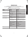
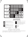
TROUBLESHOOTING GUIDE
MANY COMMON PROBLEMS CAN BE SOLVED EASILY BY UTILIZING THE CHART BELOW.
FOR MORE SERIOUS OR PERSISTENT PROBLEMS, CONTACT A D
e
WALT SERVICE CENTER OR CALL 1-(800)-4-D
e
WALT.
WARNING: To reduce the risk of serious personal injury, remove
fasteners from magazine before making any adjustments or servicing this tool.
SYMPTOM PROBLEMS SOLUTIONS
Air leak near top of tool or in trigger area Loose screws. Tighten screws.
Worn or damaged o-rings or seals. Install overhaul kit.
Tool does nothing or operates sluggishly Inadequate air supply. Verify adequate air supply.
Inadequate lubrication. Put 5 or 7 drops of oil into air inlet.
Worn or damaged valve. Install valve kit.
Air leak near bottom of tool Loose screws. Tighten screws.
Worn or damaged o-rings or bumper. Install Overhaul Kit.
Tool jams or skips frequently Incorrect fasteners. Verify approved fasteners of correct size and 15°
collation angle.
Fasteners loaded incorrectly Verify fasteners are loaded in the correct platform
position.
Damaged fasteners. Bent collation wire. Replace with undamaged fasteners.
Canister or nose screws loose Tighten screws.
Canister is dirty. Clean magazine.
Driver tip is worn or damaged. Install Driver Maintenance Kit.
Worn piston seal. Install overhaul kit.
Worn valve. Install valve kit.
Other Contact a D
e
WALT Authorized Warranty Service
Center
English
15
Page is loading ...
Page is loading ...
Page is loading ...
Page is loading ...
Page is loading ...
Page is loading ...
Page is loading ...
Page is loading ...
Page is loading ...
Page is loading ...
Page is loading ...
Page is loading ...
Page is loading ...
Page is loading ...
Page is loading ...
Page is loading ...
Page is loading ...
Page is loading ...
Page is loading ...
Page is loading ...
Page is loading ...
Page is loading ...
Page is loading ...
Page is loading ...
Page is loading ...
Page is loading ...
Page is loading ...
Page is loading ...
Page is loading ...
Page is loading ...
Page is loading ...
Page is loading ...
Page is loading ...
Page is loading ...
Page is loading ...
-
 1
1
-
 2
2
-
 3
3
-
 4
4
-
 5
5
-
 6
6
-
 7
7
-
 8
8
-
 9
9
-
 10
10
-
 11
11
-
 12
12
-
 13
13
-
 14
14
-
 15
15
-
 16
16
-
 17
17
-
 18
18
-
 19
19
-
 20
20
-
 21
21
-
 22
22
-
 23
23
-
 24
24
-
 25
25
-
 26
26
-
 27
27
-
 28
28
-
 29
29
-
 30
30
-
 31
31
-
 32
32
-
 33
33
-
 34
34
-
 35
35
-
 36
36
-
 37
37
-
 38
38
-
 39
39
-
 40
40
-
 41
41
-
 42
42
-
 43
43
-
 44
44
-
 45
45
-
 46
46
-
 47
47
-
 48
48
-
 49
49
-
 50
50
-
 51
51
-
 52
52


Ask a question and I''ll find the answer in the document
Finding information in a document is now easier with AI
in other languages
- français: DeWalt DCN45RNB Manuel utilisateur
- español: DeWalt DCN45RNB Manual de usuario
Related papers
Other documents
-
Porter Cable NS150C User manual
-
Porter-Cable DA250CC2002 User guide
-
Porter-Cable DA250C User manual
-
-
-
-
-
 Builder's Choice HDXD168028 Installation guide
-
Porter Cable RN175C User manual
-
