Owner’s Manual
1111 W. 35th Street Chicago, IL 60609 USA
Customer Support: (773) 869-1234 • www.tripplite.com
Important Safety Instructions
2
Mounting
3
Quick Installation
5
Basic Operation
7
Storage and Service
11
Español
Copyright ©2004 Tripp Lite. All rights reserved. SmartPro
®
is a registered trademark of Tripp Lite.
SmartPro
®
Rackmount
Intelligent, Line-Interactive UPS Systems
• SMX500RT1U • SMX750RT1U • SMX1500XLRT2U • SMX3000XLRT2U
• 230V Sine-Wave Input/Output • 500VA - 3000VA Capacities
• Extended-Run Options*
* SMX1500XLRT2U and SMX3000XLRT2U models
13
Battery Replacement
12
Specifications
12
Français
25
Optional Installation
6
Russian
37
200309053 93-2186 SmartProInt Owner’s Manual.qxd 3/30/2004 11:42 AM Page 1

2
Important Safety Instructions
SAVE THESE INSTRUCTIONS
This manual contains important instructions that should be followed during the installation, operation
and storage of all Tripp Lite UPS Systems. Failure to heed these warnings will void your warranty.
UPS Location Warnings
• Use caution when lifting your UPS. Because of the considerable weight of all rackmount UPS
systems, at least two people should assist in lifting and installing them.
• Install your UPS indoors, away from excess moisture or heat, dust or direct sunlight.
• For best performance, the ambient temperature near your UPS should be between 0° C and
40° C (between 32° F and 104° F).
• Leave adequate space around all sides of the UPS for proper ventilation. Do not obstruct its
vents or fan openings.
UPS Connection Warnings
• The UPS contains its own energy source (battery). The output terminals may be live even
when the UPS is not connected to an AC supply.
• Connect your UPS to a properly grounded AC power outlet. Do not modify the UPS’s plug
in a way that would eliminate the UPS's connection to ground. Do not use adapters that
eliminate the UPS’s connection to ground.
• Do not plug your UPS into itself; this will damage the UPS and void your warranty.
• If you are connecting your UPS to a motor-powered AC generator, the generator must provide
filtered, frequency-regulated computer-grade output.
Equipment Connection Warnings
• Do not use Tripp Lite UPS Systems for life support applications in which a malfunction or
failure of a Tripp Lite UPS System could cause failure or significantly alter the performance
of a life-support device.
• Do not connect surge suppressors or extension cords to the output of your UPS. This might
overload the UPS and will void the surge suppressor and UPS warranties.
Battery Warnings
• Except for battery replacement, your UPS does not require routine maintenance. Do not open
your UPS for any reason. There are no user-serviceable parts inside.
• Because batteries present a risk of electrical shock and burn from high short-circuit current,
qualified service personnel should observe proper precautions: Use tools with insulated handles
and replace the existing batteries with the same number and type of new batteries (Sealed
Lead-Acid). Do not open the batteries. Do not short or bridge the battery terminals with any
object. Tripp Lite offers a complete line of UPS System Replacement Battery Cartridges
(R.B.C.). Visit Tripp Lite on the Web at www.tripplite.com/support/battery/index.cfm to locate
the specific replacement battery for your UPS.
• During hot-swap battery replacement, the UPS will not provide backup power in the event of
a blackout or other power interruptions.
• Do not operate UPS without batteries.
• Do not dispose of the batteries in a fire. The UPS batteries are recyclable. Refer to local codes
for disposal requirements.
• When adding external battery packs to select models with external battery pack connectors,
connect only Tripp Lite-recommended battery packs of the correct voltage and type. Do not
connect or disconnect battery packs when the UPS is operating on battery power.
200309053 93-2186 SmartProInt Owner’s Manual.qxd 3/30/2004 11:42 AM Page 2

3
Mounting (Rack)
Mount your equipment in either a 4-post or 2-post rack or rack enclosure (see next page for 2-post
mounting). The user must determine the fitness of hardware and procedures before mounting. If
hardware and procedures are not suitable for your application, contact the manufacturer of your rack
or rack enclosure. The procedures described in this manual are for common rack and rack enclosure
types and may not be appropriate for all applications.
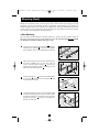
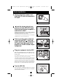
4-Post Mounting
All UPS models include hardware required to mount in a 4-post rack. Select models include an
adjustable rackmount shelf kit to provide additional support. If your UPS model does not
include
an adjustable rackmount shelf kit, skip steps 1 and 2.
Connect the two segments of each shelf using the
included screws and nuts . Leave the screws slightly
loose so that the shelves can be adjusted in the next step.
Adjust each shelf to fit your rack, then mount them in
the lowest available space of your rack with the
screws, nuts and washers provided . Note that the
support ledges should face inward. Tighten the screws
that connect the shelf segments .
Attach mounting ears to the front mounting holes
of your UPS using the screws provided . The
ears should face forward.
Using an assistant if necessary, lift your UPS and slide
it onto the mounting shelves (if your model includes
the shelves). Attach your UPS to the rack by using the
appropriate hardware through its mounting ears
and into the rack rails.
F
ED
C
A
B
B
A
1
2
3
A
B
B
A
D
C
E
F
1
2
3
4
4
200309053 93-2186 SmartProInt Owner’s Manual.qxd 3/30/2004 11:42 AM Page 3

Mounting (Rack)
continued
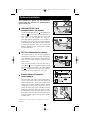
2-Post (Telecom) Mounting
Mount 1U UPS models in 2-post racks with user-supplied hardware following the procedure below.
If you mount 2U UPS models in 2-post racks, they require the addition of a Tripp Lite 2-Post
Rackmount Installation Kit (model: 2POSTRMKIT, sold separately). See Installation Kit owner’s
manual for installation procedure for 2U UPS models.
Attach mounting ears to the front mounting holes of
your UPS using the screws provided . The ears
should face backward.
Using an assistant if necessary, lift your UPS and
attach it to the rack by passing the screws, nuts and
washers provided through its mounting ears and
into the rack rails.
D
C
B
A
1
2
B
A
D
C
1
2
Mounting (Tower)
4
Mount all UPS models in an upright, tower position using included hardware. The user must deter-
mine the fitness of hardware and procedures before mounting.
All UPS Models
Stand your UPS on its side with the LED/Control panel at
the top. Attach one rack mounting ear to each side of the
UPS using included screws.
2U UPS Models Only
Rotate the LED/Control panel to view it easier while the
UPS is tower mounted. Insert a small screwdriver, or other
tool, in the slots on either side of the panel. Pop the panel
out; rotate it; and pop the panel back in place.
A
A
200309053 93-2186 SmartProInt Owner’s Manual.qxd 3/30/2004 11:42 AM Page 4

5
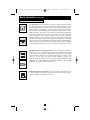
Quick Installation
Unplug computer’s power cord
from both AC outlet and computer’s
AC input.
Insert the female plug of com-
puter’s cord into UPS’s AC input.
Insert the male plug of computer’s
cord into AC outlet.*
NOTE! after you plug the UPS into a live AC outlet, the UPS will
automatically charge its batteries,** but will not supply power to its
outlets until it is turned ON (see Step 3 below).
* See Specifications for circuit amperage requirements. ** The BATTERY
CHARGE LED will be the only LED illuminated.
Find one of the power cords that
came with the UPS. Insert the
cord’s female plug into computer’s
AC input. Insert the cord’s male
plug into any of UPS’s female output
receptacles.
Plug your equipment into the UPS.*
Plug your equipment into the UPS. Repeat step 3
above using the additional power cord(s) that came
with the UPS.
Note: Additional interconnection cords (C13 to C14) are available
from Tripp Lite. Call 773-869-1234 (Part # P004-006).
* Your UPS is designed to support only computer equipment. You will
overload the UPS if the total VA ratings for all the equipment you connect
exceeds the UPS's Output Capacity (see Specifications). To find your
equipment's VA ratings, look on their nameplates. If the equipment is
listed in amps, multiply the number of amps by 240 to determine VA.
(Example: 1 amp × 240 = 240 VA). If you are unsure if you have overloaded
the UPS’s outlets, see “OUTPUT LOAD LEVEL” LED description.
Turn the UPS ON.
Press and hold the “POWER” button for one second.
The alarm will beep once briefly after one second has
passed. Release the button.
B
A
1
1
2
2
IEC320-C14 plug shown
3
A
4
5
5
3
4
B
200309053 93-2186 SmartProInt Owner’s Manual.qxd 3/30/2004 11:42 AM Page 5

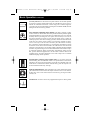
Optional Installation
These connections are optional. Your UPS will function
properly without these connections. Note: SMX3000XLRT2U
shown in all diagrams.
USB and RS-232 Serial
Communications (all models)
Use the included USB cable (see ) and/or DB9 serial
cable (see ) to connect the communication port on
your computer to the communication port of your
UPS. Install on your computer the Tripp Lite
PowerAlert Software appropriate to your computer’s
operating system. Your UPS may feature additional
communications ports; these ports may also be connected
to additional computers which have PowerAlert
Software installed. Consult your PowerAlert manual
for more information.
EPO Port Connection (all models)
This optional feature is only for those applications
which require connection to a facility’s Emergency
Power Off (EPO) circuit. When the UPS is connected
to this circuit, it enables emergency shutdown of the
UPS’s inverter.
Using the cable provided, connect the EPO port of
your UPS (see ) to a user-supplied normally closed or
normally open switch according to the circuit diagram
(see ). The EPO port is not a phone line surge sup-
pressor; do not connect a phone line to this port.
External Battery Connection
(select models)
All UPS models come with a robust internal battery
system; select models feature connectors that accept
optional external battery packs (sold separately from
Tripp Lite*) to provide additional runtime. Adding
external batteries will increase recharge time as well as
runtime. See battery pack owner’s manual for complete
installation instructions. Make sure cables are fully
inserted into their connectors. Small sparks may result
during battery connection; this is normal. Do not connect
or disconnect battery packs when the UPS is running
on battery power.
* See Specifications section for battery packs available for your specific
UPS model.
2b
2a
1b
1a
4-5
6
1b
1a
2a
2b
3
1
2
3
200309053 93-2186 SmartProInt Owner’s Manual.qxd 3/30/2004 11:42 AM Page 6

7
“POWER” Button
• To turn the UPS ON: with the UPS plugged into a live AC wall outlet*, press
and hold the POWER button for one second.** Release the button. If utility
power is absent, you can “cold-start” the UPS (i.e.: turn it ON and supply power
for a limited time from its batteries***) by pressing and holding the POWER
button for one second.**
• To turn the UPS OFF: with the UPS ON and receiving utility power, press and
hold the POWER button for one second.** Then unplug the UPS from the wall
outlet. The UPS will be completely OFF.
* After you plug the UPS into a live AC outlet, the UPS will automatically charge its batteries, but will
not supply power to its outlets until it is turned ON. ** The alarm will beep once briefly after the indi-
cated interval has passed. *** If fully charged.
“MUTE/TEST” Button
To Silence (or “Mute”) UPS Alarms: briefly press and release the
MUTE/TEST button.
To Run a Self-Test: with your UPS plugged in and turned ON, press and hold
the MUTE/TEST button for two seconds.* Continue holding the button until
the alarm beeps several times and the UPS performs a self test. See “Results of
a Self-Test” below. Note: you can leave connected equipment on during a self-test.
Your UPS, however, will not perform a self-test if you have placed it in
“Standby/Charge-Only” mode (see “POWER” Button description).
CAUTION! Do not unplug your UPS to test its batteries. This will remove
safe electrical grounding and may introduce a damaging surge into your
network connections.
Results of a Self-Test: the test will last approximately 10 seconds as the UPS
switches to battery to test its load capacity and battery charge. All LEDs will
be lit and the UPS alarm will sound.
• If the “OUTPUT LOAD LEVEL” LED remains lit red and the alarm continues to
sound after the test, the UPS’s outlets are overloaded. To clear the overload,
unplug some of your equipment and run the self-test repeatedly until the
“OUTPUT LOAD LEVEL” LED is no longer lit red and the alarm is no
longer sounding.
CAUTION! Any overload that is not corrected by the user immediately
following a self-test may cause the UPS to shut down and cease supplying
output power in the event of a blackout or brownout.
• If the “BATTERY WARNING” LED remains lit and the alarm continues to
sound after the test, the UPS batteries need to be recharged or replaced.
Allow the UPS to recharge continuously for 12 hours, and repeat the self-test. If the
LED remains lit, contact Tripp Lite for service. If your UPS requires battery
replacement, visit www.tripplite.com/support/battery/index.cfm to locate the spe-
cific Tripp Lite replacement battery for your UPS.
* The alarm will beep once briefly after the indicated interval has passed.
Basic Operation
Buttons (Front Panel)
200309053 93-2186 SmartProInt Owner’s Manual.qxd 3/30/2004 11:42 AM Page 7

Basic Operation
continued
Indicator Lights (Front Panel)
All Indicator Light descriptions apply when the UPS is plugged into a wall outlet
and turned ON.
“POWER” LED: this green LED lights continuously when the UPS is ON and
supplying connected equipment with AC power from a utility source. The LED
flashes and an alarm sounds (4 short beeps followed by a pause) to indicate the
UPS is operating from its internal batteries during a blackout or severe
brownout. If the blackout or severe brownout is prolonged, you should save
files and shut down your equipment since internal battery power will eventual-
ly be depleted. See “BATTERY CHARGE” LED description below.
“VOLTAGE CORRECTION” LED: this green LED lights continuously
whenever the UPS is automatically correcting high or low AC voltage on the
utility line without the assistance of battery power. The UPS will also emit a
slight clicking noise. These are normal, automatic operations of the UPS, no
action is required on your part.
“OUTPUT LOAD LEVEL” LED: this multicolored LED indicates the
approximate electrical load of equipment connected to the UPS's AC outlets. It
will turn from green (light load) to yellow (medium load) to red (overload). If
the LED is red (either illuminated continuously or flashing), clear the overload
immediately by unplugging some of your equipment from the outlets until the
LED changes from red to yellow (or green). CAUTION! Any overload that is
not corrected by the user immediately may cause the UPS to shut down and
cease supplying output power in the event of a blackout or brownout.
“BATTERY CHARGE” LED: when the UPS is operating from utility power,
this LED indicates the approximate charge state of the UPS's internal batteries:
red indicates the batteries are beginning to charge; yellow indicates the batteries
are roughly midway through charging; and green indicates the batteries are fully
charged. When the UPS is operating from battery power during a blackout or
severe brownout, this LED indicates the approximate amount of energy (ulti-
mately affecting runtime) which the UPS’s batteries will provide: red indicates
a low level of energy; yellow indicates a medium level of energy; and green
indicates a high level of energy. Since the runtime performance of all UPS bat-
teries will gradually deplete over time, it is recommended that you periodically
perform a self-test (see MUTE/TEST Button description) to determine the energy
level of your UPS batteries BEFORE a blackout or severe brownout occurs.
During a prolonged blackout or severe brownout, you should save files and shut
down your equipment since battery power will eventually be depleted. When the
LED turns red and an alarm sounds continuously, it indicates the UPS's batteries
are nearly out of power and UPS shut down is imminent.
“BATTERY WARNING” LED: this LED lights red and an alarm sounds
intermittently after you complete a self test (See “MUTE/TEST” Button descrip-
tion) to indicate the UPS batteries need to be recharged or replaced. Allow the
UPS to recharge continuously for 12 hours, and repeat the self-test. If the LED
continues to light, contact Tripp Lite for service. If your UPS requires battery
replacement, visit www.tripplite.com/support/battery/index.cfm to locate the spe-
cific Tripp Lite replacement battery for your UPS.
8
200309053 93-2186 SmartProInt Owner’s Manual.qxd 3/30/2004 11:42 AM Page 8

9
Basic Operation
continued
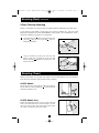
Other UPS Features (Rear Panel)
AC Receptacles: Your UPS features IEC320-C13 outlets, and select models
also feature IEC320-C19 outlets. These output receptacles provide your con-
nected equipment with AC line power during normal operation and battery power
during blackouts and brownouts. The UPS protects equipment connected to
these receptacles against damaging surges and line noise. If you have a serial or
USB connection to your UPS, you can remotely reboot connected equipment by
turning the receptacles OFF and ON using Tripp Lite's PowerAlert Software.
Select models have their receptacles divided into one or more load banks
(labelled “LOAD 1,” etc.) which may be remotely switched OFF and ON using
Tripp Lite UPS software without interrupting power to equipment connected to
the other outlets. Select models also feature outlets labelled “UNSWITCHED”,
which may not be remotely switched off. Unswitched outlets can only be turned off
by turning off all of the output receptacles. See software instructions for details.
Communications Ports (USB or RS-232): These ports connect your UPS to any
workstation or server. Use with Tripp Lite’s PowerAlert Software and included
cables to enable your computer to automatically save open files and shut down
equipment during a blackout. Also use PowerAlert Software to monitor a wide
variety of AC line power and UPS operating conditions. Consult your
PowerAlert Software manual or contact Tripp Lite Customer Support for more
information. See “USB and RS-232 Serial Communications” in the “Optional
Installation” section for installation instructions.
EPO (Emergency Power Off) Port: Your UPS features a EPO port that may
be used to connect the UPS to a contact closure switch to enable emergency
inverter shutdown. See Optional Connection.
IEC320-C13/230V
IEC320-C19/230V
200309053 93-2186 SmartProInt Owner’s Manual.qxd 3/30/2004 11:42 AM Page 9

Basic Operation
continued
Accessory Slot: Remove the small cover panel from this slot to install optional
accessories to remotely monitor and control your UPS. Refer to your accessory’s
manual for installation instructions. Contact Tripp Lite Customer Support at
(773) 869-1234 for more information, including a list of available SNMP, network
management and connectivity products.
Power Sensitivity Adjustment (Select Models): This dial is normally set fully
counter-clockwise, which enables the UPS to provide maximum protection against
waveform distortions in its AC input. When such distortion occurs, the UPS will
normally switch to providing sine wave power from its battery reserves for as
long as the distortion is present. In areas with poor utility power or where the
UPS’s input power comes from a backup generator, chronic waveform distortion
could cause the UPS to switch to battery too frequently, draining its battery
reserves. You may be able to reduce how often your UPS switches to battery
due to moderate waveform distortion by experimenting with different settings
for this dial. As the dial is turned clockwise, the UPS becomes more tolerant of
variations in its input power’s AC waveform. NOTE: The further the dial is adjusted
clockwise, the greater the degree of waveform distortion the UPS will allow to pass
to connected equipment. When experimenting with different settings for this
dial, operate connected equipment in a safe test mode so that the effect on the
equipment of any waveform distortions in the UPS’s output can be evaluated
without disrupting critical operations.
External Battery Connector (Select Models Only): Use to connect Tripp Lite
external battery packs for additional runtime. The specifications section of this
manual lists the Tripp Lite external battery packs that are compatible with your
model. Refer to instructions available with the battery pack for complete con-
nection information and safety warnings.
Input and Output Breakers: Your UPS features one or more breakers that protect
your UPS from overcurrent draw and output overload. If one or more of these
breakers trip, remove some of the load, then reset them by pressing the breaker
switch(es) in.
Ground Screw: Use this to connect any equipment that requires a chassis ground.
10
200309053 93-2186 SmartProInt Owner’s Manual.qxd 3/30/2004 11:42 AM Page 10

11
Storage and Service
Storage
Before storing your UPS, turn it completely OFF: with the UPS ON and receiving utility power,
press and hold the POWER button for one second (an alarm will beep once briefly after the inter-
val has passed); then, unplug the UPS from the wall outlet. If you store your UPS for an extended
period of time, recharge the UPS batteries once every three months: plug the UPS into a wall out-
let; allow it to charge for 12 hours; and then unplug it and place it back in storage. Note: after you
plug the UPS in, it will automatically begin charging its batteries; however, it will not supply power
to its outlets (see Quick Installation section). If you leave your UPS batteries discharged for an
extended period of time, they will suffer a permanent loss of capacity.
Service
Before returning your UPS for service, follow these steps:
1. Review the installation and operation instructions in this manual to ensure that the service
problem does not originate from a misreading of the instructions. Also, check that the UPS
System’s circuit breaker(s) are not tripped. This is the most common cause of service inquiries
which can be easily remedied by following the resetting instructions in this manual.
2. If the problem continues, do not contact or return the UPS to the dealer. Instead, call Tripp Lite
at (773) 869-1233. A service technician will ask for the UPS's model number, serial number
and purchase date and will attempt to correct the problem over the phone.
3. If the problem requires service, the technician will issue you a Returned Material Authorization
(RMA) number, which is required for service. If you require packaging, the technician can
arrange to send you proper packaging. Securely pack the UPS to avoid damage during shipping.
Do not use Styrofoam beads for packaging. Any damages (direct, indirect, special, incidental
or consequential) to the UPS incurred during shipment to Tripp Lite or an authorized Tripp Lite
service center is not covered under warranty. UPS Systems shipped to Tripp Lite or an authorized
Tripp Lite service center must have transportation charges prepaid. Mark the RMA number on
the outside of the package. If the UPS System is within the 2-year warranty period, enclose a
copy of your sales receipt. Return the UPS for service using an insured carrier to the address
given to you by the Tripp Lite service technician.
200309053 93-2186 SmartProInt Owner’s Manual.qxd 3/30/2004 11:42 AM Page 11

12
Battery Replacement
Model SMX500RT1U SMX750RT1U SMX1500XLRT2U SMX3000XLRT2U
Series # AGSMX500RT1U AGSM751SRM1U AGSM152DRTi2U AGSM4878
Input
Nominal Voltage/Frequency: 230VAC/50/60Hz 230VAC50/60Hz 230VAC50/60Hz 230VAC50/60Hz
Suggested Circuit: 10 amp 10 amp 10 amp 20 amp
Output
Capacity (VA/Watts) 500/300 750/450 1500/1000 3000/2250
On Line Nominal Voltage/Waveform: 230VAC/sine wave 230VAC/sine wave 230VAC/sine wave 230VAC/sine wave
On Battery Nominal Voltage/Waveform: 230VAC/PWM sine wave 230VAC/sine wave 230VAC/sine wave 230VAC/sine wave
Battery Runtime (Half Load/Full Load) 7/18 min. 11/26 min. 10+/25+ min.* 4+/13+ min.*
Battery Recharge Time (to 90% charge) 2-4 hrs. 2-4 hrs. 2-4 hrs. 2-4 hrs.
Typical Transfer Time 2-4 ms. 2-4 ms. 2-4 ms. 2-4 ms.
Approvals: CE CE CE CE
* Battery runtime for these models can be increased with the addition of optional external battery packs. Adding external battery packs will also increase recharge time.
ALL MODELS: Voltage-Regulated Output Voltage Range (230V +/- 9%); On Battery Output Voltage Range (230V +/- 5%); AC Surge Suppression (exceeds IEEE 587
Cat. A & B standards); AC Noise Attenuation (>40 dB); AC Protection Modes (H to N).
The policy of Tripp Lite is one of continuous improvement. Specifications are subject to change without notice.
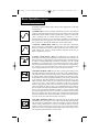
Note on Labeling
Two symbols are used on the label.
V~ : AC Voltage
V : DC Voltage
Specifications
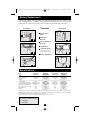
Under normal conditions, the original batteries in your UPS will last many years. See Safety section
before replacing batteries. The batteries are designed for hot-swap replacement (i.e. leaving the UPS
in ON mode), but some users may wish to put the UPS in the OFF mode before proceeding.
1U UPS Models
Procedure
Remove Front
Panel
Disconnect
Batteries
Remove/Dispose of
Batteries
Add Batteries
Connect Batteries
Attach connectors: black-
to-black and red-to-red.
Replace Front Panel
6
5
4
3
2
1
2U UPS Models
T
P
RO
®
UPS
1
6
2
5
3
4
S
MART
P
RO
®
UPS
1
6
2
5
3
4
200309053 93-2186 SmartProInt Owner’s Manual.qxd 3/30/2004 11:42 AM Page 12

1111 W. 35th Street, Chicago, IL 60609 USA
773.869.1234 (USA) • 773.869.1212 (International)
www.tripplite.com
200309053 93-2186_EN
-
 1
1
-
 2
2
-
 3
3
-
 4
4
-
 5
5
-
 6
6
-
 7
7
-
 8
8
-
 9
9
-
 10
10
-
 11
11
-
 12
12
-
 13
13


Tripp Lite AGSM152DRTi2U User manual
- Type
- User manual
- This manual is also suitable for
Ask a question and I''ll find the answer in the document
Finding information in a document is now easier with AI
Related papers
-
Tripp Lite SMART700DV Owner's manual
-
Tripp Lite BC Internet Owner's manual
-
-
-
-
-
-
-
-