Page is loading ...

DFX 100 Series • Setup Guide
The Extron DFX 100 Series consists of a transmitter (DFX 100 Tx) and receiver (DFX 100 Rx)
that use one multimode fiber optic cable to extend a DVI-D signal up to 984 feet (300 m).
This guide provides basic instructions for an experienced installer to set up and operate the
DFX 100 (for full instructions see the DFX 100 Series User Guide, at www.extron.com).
Installation
Step 1 — Mounting
Mount the DFX 100 Tx close to the DVI source and the DFX 100 Rx close to the DVI display
device. See the DFX 100 Series User Guide for all mounting options. Follow the instructions
provided with the appropriate installation kit.
Step 2 — Cable Connections
Extro n
Extro n
POWER
12V
- - A MAX
OUTPUT
INPUT
DFX 100 Tx
POWER
12V
- - A MAX
OUTPUT
INPUT
DFX 100 Tx
POWER
12V
- - A MAX
INPUT
OUTPUT
DFX 100 Rx
POWER
12V
- - A MAX
INPUT
OUTPUT
DFX 100 Rx
b
f
e
b
d
c
a
DFX 100 Series Front Panel DFX 100 Tx Rear Panel DFX 100 Rx Rear Panel
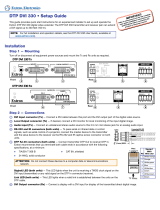
1. Connect one of the provided 12VDC power supplies to the rear panel captive screw
connectors of the transimtter and the other to the receiver (
b
).
ATTENTION: Before connecting power to the DFX 100 Tx or Rx, see the attention
box in the “Power Supply” section of the DFX 100 Series User Guide for important
information about power supplies.
NOTES:
• When the units receive power but no input signals, the front panel LED (
a
) lights
amber.
• When the transmitter receives power and a DVI input signal, the front panel LED lights
green
• When the receiver receives power and a ber optic input signal, the front panel LED
lights green.
2. Connect the DFX 100 Tx output (
d
) to the DFX 100 Rx input (
f
) using one multimode
cable (not provided).
WARNING: Possible Damage to Eyesight. The DFX 100 outputs continuous
invisible light (Class 1 rated), which may be harmful and dangerous to the eyes; use
with caution. Do not look into the rear panel ber optic cable connector or into the
ber optic cable itself. Plug the attached dust cap into the optical transceiver when
the ber optic cable is unplugged.
3. Connect the DVI display to the DVI output connector of the DFX 100 Rx (
e
). Power on the
display.
Extron Headquarters
+800.633.9876 Inside USA/Canada Only
Extron USA - West Extron USA - East
+1.714.491.1500 +1.919.850.1000
FAX:
+1.714.491.1517 +1.919.850.1001
Extron Europe
+800.3987.6673
Inside Europe Only
+31.33.453.4040
FAX:
+31.33.453.4050
Extron Asia
+800.7339.8766
Inside Asia Only
+65.6383.4400
FAX:
+65.6383.4664
Extron Japan
+81.3.3511.7655
FAX:
+81.3.3511.7656
Extron Middle East
+971.4.299.1800
FAX:
+971.4.299.1880
Extron China
+4000.EXTRON
+4000.398766
Inside China Only
+86.21.3760.1568
FAX:
+86.21.3760.1566
Extron India
1800.3070.3777
Inside India Only
+91.80.3055.3777
FAX:
+91.80.3055.3737
Extron Korea
+82.2.3444.1571
FAX: +82.2.3444.1575
© 2013 Extron Electronics All rights reserved. www.extron.com 68-2149-50 Rev A 04 13
DFX 100 Series • Setup Guide (Continued)
4. Connect the DVI source to the DVI input connector of the DFX 100 Tx (
c
). Power on the
source.
NOTE: Although the transmitter and receiver have DVI-I connectors, both devices are
compatible only with a single link DVI-D signal.
Application Diagram
POWER
12V
- - A MAX
OUTPUT
INPUT
DFX 100 Tx
POWER
12V
- - A MAX
DFX 100 Rx
INPUT
OUTPUT
Extron
DFX 100 Tx
Transmitter
Extron
DFX 100 Rx
Receiver
PC
DVI
DVI
Fiber
Flat Panel Display
Up to 300m ( 984 ft )
on Multimode Fiber
/


