Page is loading ...

“The mission of Boston Whaler® is to
provide consumers with the
safest, highest quality, most durable
boats in the world”
INFORMATION IN THIS PUBLICATION IS BASED ON THE LATEST PRODUCT SPECIFICATIONS AVAILABLE AT PRINTING, BOSTON WHALER® BOATS, INC. RESERVES THE RIGHT
TO MAKE CHANGES AT ANY TIME WITHOUT NOTICE, IN THE COLORS, EQUIPMENT, SPECIFICATIONS, MATERIALS AND PRICES OF ALL MODELS, OR TO DISCONTINUE MODELS.
SHOULD CHANGES OR MODIFICATIONS TO THE MODELS BE MADE BOSTON WHALER® IS NOT OBLIGATED TO MAKE SIMILAR CHANGES OR MODIFICATIONS TO MODELS
SOLD PRIOR TO THE DATE OF SUCH CHANGES. THE FOLLOWING ARE REGISTERED TRADEMARKS OF THE BRUNSWICK CORPORATION:
240 OUTRAGE, BOSTON WHALER®. MRP #1808105
Rev E 10/11/05

Boston Whaler founder
Richard T. Fisher demon-
strating one of the fea-
tures that has made Bos-
ton Whaler the “Unsink-
able Legend” in this 1961
LIFE Magazine Photo.
Richard T. Fisher was
posthumously inducted
into the National Marine
Manufacturer’s Associa-
tion (NMMA) Hall of Fame
on September 26, 1996
for accomplishments
made in marine engineer-
ing and construction.
History
In 1958, company founder Richard T. Fisher introduced the first Boston Whaler boat in Braintree,
Massachussetts. It featured two significant innovations: first, its twin sponson hull design produced superior
stability and a remarkably dry ride; second, its unique foam core construction made the boat not only du-
rable, but unsinkable as well. Fisher took every opportunity to illustrate the unique characteristics of the
Boston Whaler. His most famous demonstration was captured in 1961, by Life Magazine. The series of
photographs showed the boat underway, the boat being sawed in half and ultimately Fisher motoring away in
the remaining half of the boat. And through the years many other demonstrations have proved the toughness
and durability of the Boston Whaler hull. And though you may never cut your boat in half, this only goes to
show one thing, people whose livelihood and lives depend on boats consistently choose Boston Whaler
because of their seaworthiness, dependablility and the inherent safety of a hull that won’t sink even if se-
verely damaged. Boston Whalers are built to last. For over 40 years Boston Whaler® has strived to make
each model better, providing you with a safe and fun boating experience. That is the reason we offer a 10
year limited transferable warranty. It is also an excellent reason why you can trust the safety of your family
and friends to a Boston Whaler.
PLEASE KEEP THIS BOOK AND OTHER MATERIALS IN A SECURE PLACE, AND BE SURE TO HAND IT
OVER TO THE NEW OWNER IF YOU SELL THE BOAT.

Section 1 - 240 Outrage
Table of Contents
240 Outrage-Owner’s Manual
Section 1-240 Outrage
Introduction 1
Table of Contents 1
Construction Standards 2
Our Hull 2
Servicing your Boston Whaler 2
Hull Identification Number 2
Section 2-General Arrangement & Specifications
240 Outrage-Specifications & Dimensions 3
Standard Features 4
Notable Options 5-6
Through-hull Fittings 7
Storage 8
Standard Seating Arrangement 9
Optional Seating Arrangement 9
Label Locations 10
Deck Occupancy 10
Section 3-Fuel System
Fuel System Diagram 11
Fuel Tank 11
Fuel Fill 11
Fuel Vent 11
Empty Tank 12
Hoses & Fittings 12
Tank Cleaning 12
Primer Bulb 12
Remote Oil System 12
Static Electricity and the Fuel System 13
Section 4-Electrical System
Battery Information 14
Battery Maintenance 14
Dual Battery Switches 15
Console Wiring Diagram 16
Console Wiring Diagram, Engine Start 16
Main Breaker Panel Wiring Diagram 17
Hull Wiring Diagram 17
Instrument Panel Arrangement, Single Engine 18
Instrument Panel Arrangement, Dual Engine 19
Multi-System Tachometer 20
Multi-System Speedometer 20
Smartcraft® System View 20
Main Breaker Panel 21
Engine Starting Procedure 22
Ignition Shutdown Switch 22
Navigation Lighting 23
Section 5-Water & Waste System
Freshwater System 24
Freshwater Pump 24
Freshwater Shower 24
Maintenance 24
Disinfecting the System 24
Freshwater System Diagram 24
Winterizing the System 25
Raw Water 25
Operation/Maintenance 25
Raw Water System Diagram 25
This Owner’s Manual has been written to provide specific information about your boat and it should be read carefully. Keep this booklet in the
Owner’s Manual Packet. The Owner’s Manual Packet has been compiled to help you operate your boat with safety and pleasure. It contains
details of the boat, the equipment supplied or fitted, it’s systems and information on it’s operation and maintenance. Please familiarize yourself
with the boat and it’s operation before using it. If this is your first boat, or you are changing to a type of boat you are not familiar with, for your
own comfort and safety, please ensure that you obtain handling and operating experience before “assuming command” of your boat. Your
Boston Whaler® dealer or local Yacht Club will be pleased to advise you of marine safety classes and safe boating classes in your area
.
Introduction
1
Head System 26
Macerator,(optional) 26
Operation/Maintenance 26
Standard Waste System Diagram 27
Optional Waste System Diagram 27
Environmental Considerations 27
Section 6-Bilge System
Bilge Pump 28
Operation/Maintenance 28
Section 7-Livewell System
Livewell 29
Operation 29
Standard Livewell Diagram 29
Livewell,(Optional) 30
Operation/Maintenance 30
Optional Livewell System Diagram 30
Section 8-Propulsion System
Hydraulic Steering Information 31
Operation/Maintenance 31
Filling 31
Power Steering Information 32
Gear Shift & Throttle Control 32
Digital Throttle/Shift,(DTS)® 33
Power Trim Operation 33
Propeller Information 34
Propeller Assembly 34
Section 9-Getting to know your Boston Whaler
Trim Tabs 35
Operation/Maintenance 35
Mooring Points 36
Lifting 36
Hull Maintenance 37
Hull Maintenance, Blisters 37
Bottom Painting 37
Painted Hull Care, (Bottom) 38
Vinyl Cushion Care 38
Long Term Storage 38
Engine 39
Fuel System 39
Trailer Storage 39
Electrical System 39
Drainage 39
Canvas Care & Maintenance 39
Trailer (Optional) 40
Trailer Safety 40
Bunk Trailer Terminology 40
Section 10-Anchoring Information
Anchoring Information 41
Lowering 41
Setting 41
Weighing 41
Anchor Windlass, (Optional) 42
Section 11-Maintenance Log & Notes
Maintenance Log & Notes 43

150150
Section 1 - 240 Outrage
240 Outrage-Owner’s Manual
“THE MISSION OF BOSTON WHALER IS TO PROVIDE CONSUMERS WITH THE
SAFEST, HIGHEST QUALITY, MOST DURABLE BOATS IN THE WORLD”.
We are dedicated to creating a superior product providing you with comfort, performance, safety and dependability.
All of our boats comply with the safety standards set by the United States Coast Guard and are designed, engineered
and manufactured in accordance with applicable recommendations and guidelines of the American Boat and Yacht
Council (A.B.Y.C.) and certified by the National Marine Manufacturers Association (N.M.M.A.).
Construction Standards
2
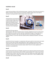
Hull Identifcation Number
The “Hull Identification Number” is located on the
starboard side of the transom wall.
This is the most important identifying factor and must
be included in all correspondence related to your ves-
sel. Failure to do so will only create delays. Also of
vital importance are the engine serial numbers and
part numbers when writing about or ordering parts
for your engine.
Our Hull
Boston Whaler® hulls are constructed with our pat-
ented Unibond™ construction. This involves shoot-
ing high density foam into a closed mold system.
The foam expands to fill voids in the hull, and when
the finished product is pulled from the mold, the deck
and the hull are chemically bonded to form a solid,
inseparable unit.
2
3
4
Hull
Identification
Number Location
When your 240 Outrage needs to be serviced or regu-
lar maintenance is needed, it should be taken to an
authorized Boston Whaler® dealer.
To find a Boston Whaler® dealer in your area call:
1-800-942-5379
Domestic/International
If a problem is not handled to your satisfaction:
Discuss any warranty related problems directly
with the service manager of the dealership or your
sales person. Give the dealership an opportunity
to help the service department resolve the matter
for you.
Servicing your Boston Whaler
Typical H.I.N. Description
1
1 No air voids
2 High density closed cell non-absorbent foam
3 High quality resins and gelcoats
4 Woven glass matting

Section 2 - General Arrangement & Specifications
240 Outrage-Owner’s Manual
3
23’9”
8’6”
27’7”
18”
** *
6’8”
9’8”
*
8’10”
Overall Length 23’9” 7.24 m
Trailerable Length 27’7” 8.41 m
Bridge Clearance 8’10” 2.69 m
Bridge Clearance (no top) 6’8” 2.03 m
Beam 8’6” 2.59 m
Draft, (Hull Only) 18” .46 m
Weight (dry, no engine) 4400 lbs. 1996 kg
Swamped Capacity 9680 lbs 4390 kg
Maximum Engine Weight 1060 lbs. 481 kg
Maximum Weight, (passengers,
engine(s), gear,** 3500 lbs 1588 kg
Persons 12
Maximum Horsepower 350HP 261 kw
Minimum Horsepower 225 HP 167 kw
Fuel Capacity 150 gal.(U.S.) 567 L
Water Capacity 20 gal.(U.S.) 76 L
* Waterline
*** Engine Draft,(See Notice)
Specifications & Dimensions
Specified measurements are approximations and are
subject to variance.
NOTICE
!
NOTICE
!
Optional equipment and loading of the boat will af-
fect the draft measurements. Follow the recommen-
dations listed on your capacity plate regarding the
maximum amount of weight the boat can safely
carry.
***
Exceeding this weight will affect the boat’s perfor-
mance. DO NOT Exceed the weights listed on the
capacity plate.
NOTICE
!
**
Note: The Hardtop shown here is
for reference purposes only.

Section 2 - General Arrangement & Specifications
240 Outrage-Owner’s Manual
4
Standard Features
1
2
3
4
5
6
7
8
9
10
11
12
13
14
15
16
17
18
19
20
21
23
22
25
24
26
29
30
31
32
33
34
35
36
37
38 39
40
41 42
44
45
46
47
48
27
43
1 Anchor Roller w/ Chafe Plate & Cleat
2 Heavy Duty Rubrail
3 Anchor Locker w/ Drain
4 Bow Navigation Light
5 Stainless Steel Forward Cleats, (8 Inch)
6 Welded Stainless Steel Low Profile Interior Rail
7 Forward In-Deck Storage w/ Hatch & Drain
8 Forward Cupholders, (2)
9 Electric Horn
10 Console Portlight
11 Stainless Steel Spring Cleat, (8 Inch)
12 Fuel Fill
See Console Detail
13 Molded, Tempered Glass Windshield
14 Compass
15 Lockable Console Storage
16 Instrument Panel
17 Stainless Steel Steering Wheel
18 Hydraulic Steering
19 Engine Safety Shut-Off Switch
20 Gear Shift/Throttle Control
21 Electric Trim Tab Switch
22 Console Cupholders, (2)
23 Console Storage Bin
24 Stainless Steel Console Grab Rail
25 Molded Console Footrests
26 Lockable Console Door, Bi-Fold
27 Forward Seating Grabrails, Port & Starboard
28 Stereo Remote (With Optional CD Player)
29 Helm & Companion Seat, Adjustable
30 Port In-Deck Insulated Fishbox
31 Gunwale Mounted Rodholders, Port & Starboard
32 Stainless Steel Hawse Pipe, Port & Starboard
33 Stern Fold-away Seat
34 18 Gal. (68.14L) Livewell Tank
35 8 Inch Access Plate, Port & Starboard
36 Sterndeck Rodholders, (3)
37 Freshwater Fill Deck Plate for 20 Gal. (75.71L) Tank
38 VRO Oil Fill Deck Plate for 3 Gal. (11.36L) Tank
39 Motorwell Access Hatch
40 225 XXL Optimax Mercury engine
41 Motorwell Drain, Port & Starboard
42 Telescoping Ladder & Grab Rail
43 Freshwater Shower/Sprayer
44 Transom Door w/ Stainless Steel Latch
45 Starboard In-Deck Insulated Fishbox
46 Waste Pump-out Deck Fitting
47 Stainless Steel Spring Cleat, (8 Inch)
48 Self-Bailing Cockpit
28

Section 2 - General Arrangement & Specifications
240 Outrage-Owner’s Manual
5
5
6
7
8
Console Interior-
Looking aft
240 Outrage, Notable Options 1
2
3
4
1 Stainless Steel Bow Rail, (deletes low profile rail)
2 Sun Lounge Filler w/ Cushion
3 Forward Coaming Bolsters
4 Anchor Windlass with Rode & Anchor
5 Hardtop Storage Bag, (Black or White)
6 Hardtop w/ Storage Bag, Radial Outriggers & 15’
Telescoping poles.
7 Electronics Box for Hardtop
8 Hardtop Mounted rodholders, (5)
9 150 CXL OptiMax Mercury Engine
10 135 CXL DTS Mercury Verado 4-stroke engine*
11 150 CXL DTS Mercury Verado 4-stroke engine*
12 175 CXL DTS Mercury Verado 4-stroke engine*
13 250 XXL DTS Mercury Verado 4-stroke engine*
14 275 XXL DTS Mercury Verado 4-stroke engine*
15 12 Volt Clarion® AM/FM Digital Stereo w/ CD
Player & 4 Waterproof Speakers w/ Remote on
console
* - Smartcraft
®
System View
- Power assisted steering
- Engines available in single or dual set-up
150 150
225
15
9 10 11 12 13 14

Section 2 - General Arrangement & Specifications
240 Outrage-Owner’s Manual
6
240 Outrage, Notable Options
5
4
1
2
3
6
8
10
12
13
7
9
14
15
11
16
17
1 Stainless Steel Leaning Post Base/Rail
2 Leaning Post Seats, (Storage Under)
3 94 Qt. (89L) Cooler
4 Bait Prep area w/ Cutting Board & Leader Holder
5 Backrest, (Rodholder, when Backrest is not in use)
6 Fold-down Footrest
Deluxe Leaning Post
7 Fiberglass Base
8 Stainless Steel Rails
9 Flip-up Thigh rise Helm Seat
10 25 Gal. (95L)Livewell w/ Light
11 Rodholders, Port & Starboard
12 Knife/Leader Holder, Port & Starboard
13 Tackle Storage Box
14 Leaning Post Canvas Cover,
(Black, Blue or White)
15 Deluxe Leaning Post Cover,
(Black, Blue or White)
16 Side curtains & visor (Blue, Black or White) for
sun-top or hardtop
17 Sun-Top w/ Boot, (Black or Blue)
18
19

Section 2 - General Arrangement & Specifications
240 Outrage-Owner’s Manual
7
240 Outrage,Through-hull Fittings
PORT
AFT
STARBOARD
5
1110
7
8
9
4
1
2
3
150150
13
14
15
17
16
10 Starboard Fishbox Outlet
11 Aft bilge drain, 1100 GPH
12 Port Deck Drain, (behind Trim Tab Ram)
13 Port Motorwell Drain
14 Livewell Drain
15 Garboard Drain
16 Starboard Motorwell Drain
17 Starboard Deck Drain, (behind Trim Tab Ram)
The deck drain provides self-bailing capabilities while the
boat is static in the water and no passengers on board.
This feature prevents the accumulation of water in the
cockpit. the drain must be in place when underway.
NOTICE
!
Depending on the type of boat you have, you may
have underwater fittings that need drain plugs.
Garboard drain plugs and fishbox drain plugs need
to be in place before the boat goes into the water.
Any fitting that will be underwater needs to be
plugged or the seacock needs to be closed
NOTICE
!
Through hull fittings should be checked for proper
seal annually. When the boat is in the water the un-
derwater fittings can be checked for dripping. It is
recommended that the underwater fittings be re-
moved, cleaned and resealed every other year.
NOTICE
!
If the through hull fittings need to be replaced, it is
recommended that an authorized Boston Whaler ®
dealer perform this type of repair. Through hull fit-
tings that are improperly installed can cause pre-
mature hull failure and may void the Boston
Whaler® limited warranty.
NOTICE
!
225
12
Livewell Drain,
Single Engine Set-up
14
6
1 Anchor Locker Drain
2 Forward In-Deck Storage Drain
3 Forward Bilge Drain, 800 GPH
4 Leaning Post Livewell Inlet, Optional
5 Fuel Vent
6 Waste Vent
7 Raw-water Inlet
8 Macerator Pump-out, Optional
9 Port Fishbox Outlet

240 Outrage, Storage
Section 2 - General Arrangement & Specifications
240 Outrage-Owner’s Manual
8
4
1
2
3
5
6
7
8
9
10
11
12
14
13
16
15
1 Port In-Deck Fishbox, Insulated
2 Starboard In-Deck Fishbox, Insulated
3 Forward In-Deck Storage w/ Hatch & Drain, (In-
sulated)
4 Anchor Locker storage w/ Drain
5 Magazine Storage
6 Port Console Storage
7 Lockable Console Storage, Bi-Fold
8 Lockable Electronics Box Door, Bi-Fold
9 Electronics Box Storage Bin
10 Starboard Console Storage
11 Optional Leaning Post Under Seat Storage
12 94 Qt.(89L) Cooler Storage, (Optional)
13 Downrigger Weight Storage, Port & Starboard
14 Under Gunwale Rodrack, Port & Starboard
15 Mast Light Storage Location
16 Optional Deluxe Leaning PostTackle Storage

Section 2 - General Arrangement & Specifications
240 Outrage-Owner’s Manual
9
Injury and possible death can occur while sitting in
areas of the boat that are not designated for seating.
Gunwales, sterndeck and portions of the bow should
not be used for sitting while underway. Movement of
passengers on the deck should be limited to decrease
the chances of slipping or falling while underway.
DANGER
Standard Seating Arrangement
Optional Seating Arrangement
1
2
1
2
3
4
7
8
6
Leaning Post w/
Cooler Option
Deluxe Leaning
Post w/ Storage
or Livewell
1 Leaning post backrest cushion, (removable)
2 Leaning post seat cushion, (storage under)
3 Deluxe Leaning post backrest
4 Deluxe Leaning Post seat cushion
5 Flip up thigh rise helm seat cushion
6 Forward console seat cushion
7 Sun Lounge cushion
8 Bow cushion
1 Helm & Companion adjustable seats with snap-
on cushions.
2 Stern fold-away seat
5
!

LABEL, WARNING CO HELM
LABEL, WARNING CO HELM
PLATE, SAFETY CANADIAN CONFORMITY BW240SP
PLATE, SAFETY CANADIAN CONFORMITY BW240SP
LABEL, DANGER CO TRANSOM
LABEL, DANGER CO TRANSOM
PLATE, BW-06 MAX ENG WT 1060LB/481KG
PLATE, BW-06 MAX ENG WT 1060LB/481KG
1811373
1811373
1746020
1746020
1811367
1811367
1811368
1811368
1743504
1743504
1754632
1754632
1745156
1745156
1810486
1810486
1752856
1752856
LABEL, PROP 65 HANG TAG
LABEL, PROP 65 HANG TAG
1795087
1795087
1810487
1810487
1743323
1743323
DECAL, MERC SMARTCRAFT NETWORKED
DECAL, MERC SMARTCRAFT NETWORKED
Section 2 - General Arrangement & Specifications
240 Outrage-Owner’s Manual
10
Accommodation deck:
This area of the boat is inside the cockpit
and includes helm seating. Movement in this
area should be done with extreme caution
while the boat is underway. A sudden shift
in boat direction can cause a loss of balance and lead to injury
or death.
Working deck:
This area is intended for occupation ONLY
while mooring, anchoring, loading/unload-
ing or when the boat is at rest. NEVER op-
erate the engine while loading or unloading
swimmers/divers from the swim platform/ladder.
Be aware of your footing while the boat is underway,
slipping or falling could result in serious injury or death,
especially if the boat is in motion or in rough water.
Keep the accommodation deck clean, so if movement
is neccessary it will be free of obstruction.
DANGER
Gelcoat surfaces are slippery when wet.Use ex-
treme caution when walking on wet surfaces. Use
care when waxing to ensure that walkways are not
made dangerously slippery.
WARNING
Never occupy the working decks while the boat is
underway. ONLY sit in areas that are designated
for sitting. NEVER sit on the gunwales (vertical
sidewalls), while the boat is moving.
WARNING
!
!
!
240 Outrage, Label Locations
1
2
3
4
8
5
16
12
10
6
13
14
9
15
11
7
7
OR
18
19
If your labels become worn or unreadable contact your
nearest Boston Whaler
®
dealer for replacement labels.
The part numbers are provided above.
NOTICE
!

Section 2 - General Arrangement & Specifications
240 Outrage-Owner’s Manual
11
GENERAL
FUEL,
The 240 Outrage is equipped with a
gasoline fuel system. Please take time
to read and understand all the fuel re-
lated information and warnings in the
engine owner’s packet. The diagrams
below show the location of the fuel fill, routing of
fuel supply hose and the location of the fuel tank
vent.
Fuel Tank
The 240 Outrage comes with a 150 Gal. (567.8 L)
aluminum fuel tank. The tank is located under the
aft section of the cockpit. Access to the fuel level
sender and engine supply line tank connections are
made through a plate on the aft section of the cock-
pit floor.
Fuel Fill
The 240 Outrage fuel fill is located in the port side
amidship of the gunwale, it is marked “GAS”, and is
opened by use of a special key that is included with
the owner’s manual packet. Follow the engine
manufacturer’s recommendation for the types of fuel
to use.
Fuel Vent
The fuel tank has a fuel tank vent located amidship,
7-9” inches below the rub rail directly below the fuel
fill cap. The fuel tank vent serves as a pressure/
vacuum release, safety overflow and flame arrestor.
1
2
3
4
5
6
7
8
Sterndeck & cockpit
floor has been re-
moved for clarity.
240 Outrage Fuel System
1 5/8” fuel vent
2 1-1/2” Fuel fill to deck plate
3 150 Gal. (567.8L) Aluminum fuel tank
4 Ground wire
5 Fuel sender
6 Engine fuel supply, Standard
7 Engine fuel supply, Optional
8 Primer bulb
Fuel System
CAUTION
!
Leaking fuel is a fire and explosion hazard, inspect the
system regularly. Examine fuel tanks and exposed lines
for leaks and corrosion.
DANGER
!
Check for leaks in tubing, connections and hoses. Cor-
rect the cause of the leaks and ventilate the area to
insure that no fumes remain, prior to energizing any
electrical equipment and/or starting the engines.
CAUTION
!
Use of improper gasolines can damage your engine se-
riously. Engine damage resulting from use of improper
gasoline is considered misuse of engine and will void
the warranty. Follow engine manufacturer’s recommen-
dations regarding the types of fuel and oil to use.
CAUTION
!
Oil and fuel spills can be dangerous and can subject
offenders to severe penalties
NOTICE
!
Remove portable tanks from boat and fill from shore.
When fueling is complete, secure tanks to deck with
straps provided.
DANGER
!
Static electricity can ignite gasoline vapors causing
serious injury/death and/or destruction of property.
NOTICE
!
Fuel tanks should never be filled to capacity, allow 2%
for expansion.

EMPTY TANK:
A fuel tank with levels less than 1/4 full can cause
problems by stalling an engine due to fuel starvation
or by allowing sediment and dirt to enter the fuel
supply lines. Keeping the tank filled will reduce the
chance of this occurance; since the residue will most
likely settle to the bottom of the tank. Monitor the
fuel level often to prevent this from happening.
HOSES AND FITTINGS:
Hoses and fittings should be inspected at least every
100 hours. Check the hoses for cracks, abrasions and
deterioration and the strong smell of fuel prior to
starting the engine(s). If the hoses or fittings are dam-
aged or worn, replace them with only marine grade
replacement parts. Your authorized Boston Whaler®
dealer will have all the parts information you will
need.
TANK CLEANING:
Excessive water and sediment may force you to con-
sider having the tank professionally cleaned. If you
are frequently changing fuel filter/water separators
and notice a loss in power, consult a professional
tank cleaning contractor regarding this procedure and
proper disposal of residue and water.
PRIMER BULB:
There is a primer bulb that can be accessed under
the portside of the motorwell hatch. There are also
instructions regarding proper use of the primer bulb.
The primer bulb is used to draw fuel from the tank
to the engine, usually after the fuel has been drained
from the entire system.
Remote Oil System
The 240 Outrage is equipped with a remote oil sys-
tem. This system consists of a two 3- Gal.(11.3L)
reservoir tanks and hoses which contain and meter
lubricating oil to the engine(s). The tanks have an
external fill located on the aft side of the cockpit tran-
som wall. Access to the tanks is through the
motorwell access hatch. When recapping the fill
make sure that it is secure to prevent spills and to
prevent the intrusion of water into the system. Your
remote oil tank is secured by a nylon strap and quick
release clip. Little maintenance is required for the
remote oil system, aside from checking the hoses for
abrasions and cracks and hose clamps for proper
tightness. The tank should not be exposed to ultra-
violet light, rain or seawater for extended periods of
time. The Four-Stroke engine option deletes the re-
mote oil system.
Remote Oil Tank
Location
(sterndeck has
been removed)
Standard engine oil
supply, 3 Gal.
(11.3L)
To oil fill, for Single
Engine on sterndeck,
(dual engine tank and
fill is mounted directly
opposite this location)
Section 3 - Fuel System
240 Outrage-Owner’s Manual
12
To Engine
Motorwell
hatch
Primer
bulb
Access to the vent fittings is through twist-out plate
located inside the cockpit opposite the fuel tank vent.
Check the vent assembly regularily as part of a main-
tenance schedule for continued safe operation of your
boats fuel system. The Vent assembly consists of a
backshell, starwasher,nut and hose clamp. Remove
the hose clamp, nut, starwasher and backshell and
push the fuel vent fitting out. The fuel vent has four
screens that are held in by a ring. Use a small pick to
dislodge the ring to remove the screens and clean as
required.
Hull
mounted
fuel vent
with screen

Section 3 - Fuel System
240 Outrage-Owner’s Manual
13
• Fuel tanks should never be filled to capacity. al-
low 2% for expansion.
• Portable tanks should only be filled while on the
ground; never on-board the boat.
There is a danger that static electricity can ignite gaso-
line vapors that have not been ventilated outside an
enclosed area. Use extreme caution when fueling
your boat from a source outside the regular venues,
(e.g. marinas, fuel service stations.)
Your boat has safety features that can be circum-
vented by not adhering to standard fueling practices.
Your boats bonding system protects it from creating
and discharging static electricity.
Your boat must be in contact with the water or a land
based grounding system. Here are some helpful sug-
gestions to keep you safe from static electricity while
refueling your boat.
• NEVER fuel your boat in unsafe conditions such
as: suspended on a sling or in a situation that in-
creases the likelihood of static discharge.
• NEVER use homemade containers to fill your fuel
tanks.
• Fuel carried on-board outside of a fixed fuel sys-
tem should be stored in an approved container or
in a portable tank such as provided for outboard
engines and be stowed safely outside of the engine
or living compartment(s).
• Shut down the engine(s), motors and fans prior to
taking on fuel. Any ignition sources should be ex-
tinguished before filling the fuel tank(s).
• Close all ports, windows, doors and hatches.
• Fueling should never be done at night except in
well-lighted areas.
• Always keep the fuel nozzle in contact with the
fuel fill plate or the edge of the fuel tank opening
throughout the filling process.
• Allow areas where gasoline vapors could collect
to be ventilated before starting the engine(s).
• Wipe any spillage completely and dispose of rags
or waste on shore.
• Secure the fill cap tightly.
Static Electricity and the Fuel System

Section 3 - Fuel System
240 Outrage-Owner’s Manual
14
Electrical System
Battery Information
BATTERY
-
+
Batteries should always be enclosed in the covered
battery boxes provided with your boat. The box will
contain any spilled acid, as well as protect the bat-
tery terminals from damage or inadvertant shorting
from coming in contact with metal objects. Each bat-
tery box should always be secured in place by using
the straps and clamps provided, the straps will en-
sure that while underway the battery will not move
around, causing damage to components stored in the
same area.
BATTERY BOX LOCATION:
The 2 standard battery boxes can be accessed through
a door in the aft section of the console interior.
Battery Maintenance
Battery maintenance should include:
• Inspect each battery and charging system before
use; for loose connections or wiring.
• Coat the terminals with dielectric grease.
• Keep the batteries dry.
• Remove the batteries from the boat during cold
weather or long term storage.
The most life shortening experience for the battery
is to be drained to zero charge before recharging.
When a battery discharges, the active material on both
positive and negative plates converts to lead sulfate,
causing the plates to become more alike in an elec-
trical charge. The electricity conducting battery acid
becomes weaker and the voltage drops. As the bat-
tery remains discharged, the process continues until
recharging the battery becomes impossible.
Battery Box
Release Strap
Tie-down
strap
Never reset a breaker without first determining and
correcting the cause of the trip. Should a circuit re-
peatedly trip, have a qualified electrician determine and
correct the cause.
• Never use an open flame in the battery storage area.
• Avoid striking sparks near the battery
• A battery will explode if a flame or spark ignites the
free hydrogen given off during charging.
• The battery should always be disconnected before doing
any work or maintenance on the electrical system.
If equipped with a battery switch, you will need to stop the
engine before moving the switch to the “OFF” position.
Batteries contain sulfuric acid which is dangerous and
can cause serious injury.AVOID contact with skin, eyes
and clothing. If contact occurs, immediately flush the
affected area with large quantities of water and call for
medical assistance.
Always store the battery in the the battery box. Use the
straps and clamp to keep the box secure while underway.
CAUTION
CAUTION
CAUTION
DANGER
NOTICE
!
!
!
!
!
Your 240 Outrage is equipped with
an electrical system that provides
power for the following:
• Engine ignition
• Engine tilt trim system
• Helm switch panel & helm instrument panel
• Lighting/Navigation system
• Livewell system
• Add-on accessories and electronics
The system consists of the following components:
• Battery boxes, (2 standard)
• Battery switch, (2nd switch optional)
• Main & Branch circuit breakers
• Helm Ignition, Switch & Instrument Panel

Section 4 - Electrical System
240 Outrage-Owner’s Manual
15
ALL
2
1
OFF
Your 240 Outrage uses a battery selector switch to
control delivery of DC power from two batteries. The
battery switch is located below the breaker panel on
the aft bulkhead inside the console.
The dual battery switch has four (4) settings:
• “OFF”, you will have no power to the engine(s).
• “ALL”, you will have power from both batteries
at the same time. This parallels the batteries to
assist you in starting the engine(s), once the en-
gine is started the battery switch should be taken
off of the “ALL” setting, and set to charge either
battery .
• “1”, you will have power from the port battery only.
• “2”, you will have power from the starboard
battery only.
When the engines are shut down or not providing a
charge, the system will draw power from the star-
board battery. This will allow you to run all the boats
functions without affecting the port battery. You can
run the starboard battery flat and still start the en-
gines by moving the selector knob on the battery
switches to the “ALL” position. The battery switches
are located below the breaker panel on the aft bulk-
head inside the console. When looking at the panel,
the switch on the left is for the port battery and en-
gine, the right switch is for the starboard battery and
engine.
Dual Battery Switches
Selector Knob
“Battery 1”
Selection
“Battery 2”
Selection
Batteries
“OFF”
Selection
Batteries
“ALL”
Selection
Dual Engine Battery Switch Configuration
Both batteries un-connected, preferred position when boat
is not in use.
STARBOARD ENGINE
ALL
2
1
OFF
Normal position while engaging in normal engine opera-
tions.
To parallel batteries, set both switches to the “ALL” po-
sition.
Return to normal operating positions after starting.
Do not operate boat with batteries in parallel, seri-
ous engine electrical damage may result.
WARNING
WARNING
ALL
2
1
OFF
ALL
2
1
OFF
ALL
2
1
OFF
ALL
2
1
OFF
ALL
2
1
OFF
PORT ENGINE
The bilge pump will still draw power from the batter-
ies, even if the switches are set to “OFF”.
!
!
If the battery does become run down be sure to re-
charge it as soon as possible. Over charging the bat-
tery can be just as detrimental to its life as running it
down too far.

Section 4 - Electrical System
240 Outrage-Owner’s Manual
16
ELECTRICAL
SYSTEM
This owner’s manual contains schematics for your boat. These electrical schematics were
generated by technicians in our Engineering Department and are for reference and to be used
by service technicians. Boston Whaler® does not recommend that you attempt to work on
the electrical system yourself, instead we suggest that you take it to an authorized Boston
Whaler® dealer for electrical service. Boston Whaler® reserves the right to change or up-
date the electrical system on any model at any time without notice to the consumer and is not obligated to
make any updates to units built prior to the changes.
Console Wiring Diagram
Console Wiring Diagram
(Engine Start)

Section 4 - Electrical System
240 Outrage-Owner’s Manual
17
Main Breaker Panel
Hull Wiring Diagram

Section 4 - Electrical System
240 Outrage-Owner’s Manual
18
240 Outrage, Single Engine
Instrument Panel Arrangement
1
2 3
4 5
6
7
8
9
10 11
18
17 16
15 14
12 13
22
21 20
19
23
2 3
4 5
6
24
9
10 11
12 13
18
17 16
15 14
25
19
15 Accessory-1
16 Livewell light
17 Livewell Pump
18 12 Volt Accessory Receptacle
19 Air Temperature Sensor
20 Courtesy Lights
21 Engine Start
22 Engine Ignition
23 Instrument Panel, Verado Single Engine
24 Smartcraft
®
System View, Single Engine
25 Engine Start/Stop
1 Instrument Panel, Deluxe Single Engine
2 Horn
3 Navigation/Anchor Light
4 Forward Bilge Pump
5 Aft Bilge Pump
6 Interior Lights
7 Multi-System Display Speedometer
8 Multi-System Display Tachometer
9 Port Fishbox Pump
10 Starboard Fishbox Pump
11 Freshwater Pump
12 Raw Water Pump
13 Spreader Lights
14 Accessory-2
20
/