Page is loading ...

NATURAL GAS
CONSTRUCTION HEATER
OWNER’S MANUAL
Save this manual for future reference.
Save this manual for future reference.
For more information, visit www.desatech.com
For more information, visit www.desatech.com
TM
GENERAL HAZARD WARNING:
FAILURE TO COMPLY WITH THE PRECAUTIONS AND INSTRUCTIONS PROVIDED
WITH THIS HEATER, CAN RESULT IN DEATH, SERIOUS BODILY INJURY AND
PROPERTY LOSS OR DAMAGE FROM HAZARDS OF FIRE, EXPLOSION, BURN,
ASPHYXIATION, CARBON MONOXIDE POISONING, AND/OR ELECTRICAL SHOCK.
ONLY PERSONS WHO CAN UNDERSTAND AND FOLLOW THE INSTRUCTIONS
SHOULD USE OR SERVICE THIS HEATER.
IF YOU NEED ASSISTANCE OR HEATER INFORMATION SUCH AS AN INSTRUCTIONS
MANUAL, LABELS, ETC. CONTACT THE MANUFACTURER.
IMPORTANT: Read and understand this manual before assembling, starting, or servic-
ing heater. Improper use of heater can cause serious injury. Keep this manual for future
reference.
Model BNG150T 150,000 Btu/Hr
With Built-in Thermostat
TABLE OF CONTENTS
SAFETY INFORMATION ............................................................ 2
PRODUCT IDENTIFICATION ..................................................... 3
UNPACKING ............................................................................... 3
THEORY OF OPERATION ......................................................... 3
NATURAL GAS SUPPLY ............................................................ 3
VENTILATION............................................................................. 3
INSTALLATION ........................................................................... 4
OPERATION ............................................................................... 4
STORAGE................................................................................... 5
MAINTENANCE .......................................................................... 5
SERVICE PROCEDURES .......................................................... 5
ILLUSTRATED PARTS BREAKDOWN AND PARTS LIST ......... 6
SPECIFICATIONS ...................................................................... 8
TECHNICAL SERVICE ............................................................... 8
REPLACEMENT PARTS ............................................................ 8
WIRING DIAGRAMS................................................................... 8
WARRANTY INFORMATION.....................................Back Cover
150 LP SIDE PV 017

103887-01C
2
For more information, visit www.desatech.com
For more information, visit www.desatech.com
\SAFETY INFORMATION
SAFETY INFORMATION
WARNING: FIRE, BURN, INHALATION, AND EX-
PLOSION HAZARD. KEEP SOLID COMBUSTIBLES,
SUCH AS BUILDING MATERIALS, PAPER OR CARD-
BOARD, A SAFE DISTANCE AWAY FROM THE
HEATER AS RECOMMENDED BY THE INSTRUC-
TIONS. NEVER USE THE HEATER IN SPACES WHICH
DO OR MAY CONTAIN VOLATILE OR AIRBORNE
COMBUSTIBLES, OR PRODUCTS SUCH AS GASO-
LINE, SOLVENTS, PAINT THINNER, DUST PARTICLES
OR UNKNOWN CHEMICALS.
WARNING: Not for home or recreational vehicle use.
WARNINGS
The heater is designed for use as a construction heater. Certain
standards govern the use of fuel gases and heating products for
specific uses. Your local authority can advise you about these. The
primary purpose of construction heaters is to provide temporary
heating of buildings under construction, alteration or repair. Prop-
erly used, the heater provides safe economical heating. Products of
combustion are vented into the area being heated.
We cannot foresee every use which may be made of our heaters.
Check with your local fire safety authority if you have questions
about heater use.
Carbon Monoxide Poisoning: Some people are more affected by
carbon monoxide than others. Early signs of carbon monoxide poison-
ing resemble the flu, with headaches, dizziness, and/or nausea. If you
have these signs, the heater may not be working properly. Get fresh air
at once! Check for proper ventilation and have heater serviced.
Natural Gas: Natural gas has a distinctive odor. This odor helps you
detect a natural gas leak. However, the odor may fade. Natural gas
may be present even though no odor exists.
Make certain you read and understand all Warnings. Keep this
manual for reference. It is your guide to safe and proper operation
of this heater.
• Install and use heater with care. Follow all local ordinances and
codes. In the absence of local ordinances and codes, refer to the
National Fuel Gas Code Handbook, NFPA54/ANSI Z223.1 and
the Natural Gas Installation Code, CAN/CGA B149.1. This in-
structs on the safe storage and handling of flammable gases.
• Use only the electrical voltage and frequency specified on
model plate. The electrical connections and grounding of the
heater shall follow the National Electric Code, ANSI/NFPA 70
or the Canadian Electrical Code, Part 1.
• Electrical grounding instructions — This appliance is equipped
with a three-prong (grounding) plug for your protection against
shock hazard and should be plugged directly into a properly
grounded three-prong receptacle or extension cord.
• Use only with natural gas. Do not attempt to use with pro-
pane/LP gas.
• Provide adequate ventilation. Before using heater, provide at
least a three-square-foot opening of fresh, outside air for each
100,000 Btu/Hr of rating.
• This heater produces carbon monoxide, which is listed by the
State of California as a reproductive toxin under Proposition 65.
• For indoor use only. Do not use heater outdoors.
• Keep heater away from strong drafts, wind, water spray, rain,
or dripping water.
• Do not use heater in occupied dwellings or in living or sleep-
ing quarters.
• Do not use heater in a basement or below ground level.
• Keep appliance area clear and free from combustible materi-
als, gasoline, paint thinner, and other flammable vapors and
liquids. Dust is combustible. Do not use heater in areas with
high dust content.
• Minimum heater clearances from combustible materials:
Outlet: 8 Ft. Sides: 2 Ft. Top: 6 Ft. Rear: 2 Ft.
• Check heater for damage before each use. Do not use a dam-
aged heater.
• Check hose (if used) before each use of heater. If highly worn
or cut, replace with hose specified by manufacturer before us-
ing heater.
• Do not alter heater. Keep heater in its original state.
• Do not use heater if altered.
• Locate heater on stable and level surface if heater is hot or
operating.
• Never block air inlet (rear) or air outlet (front) of heater.
• Do not leave heater unattended.
• Keep children and animals away from heater.
• This heater is equipped with a thermostat. Heater may start at
anytime.
• Never move, handle, or service a hot or operating heater. Se-
vere burns may result. You must wait 15 minutes after turning
heater off.
• To prevent injury, wear gloves when handling heater.
• Never attach duct work to heater.
• Turn off natural gas supply to heater and unplug heater when
not in use.
• Use only original replacement parts. This heater must use de-
sign-specific parts. Do not substitute or use generic parts. Im-
proper replacement parts could cause serious or fatal injuries.

103887-01C
3
3
For more information, visit www.desatech.com
For more information, visit www.desatech.com
PRODUCT IDENTIFICATION
UNPACKING
THEORY OF OPERATION
NATURAL GAS SUPPLY
VENTILATION
PRODUCT IDENTIFICATION
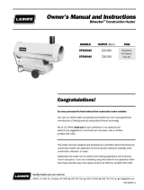
Figure 1 - 150,000 Btu/Hr Model
Hot Air Outlet
(Front)
Handle
Fan
Guard
Upper Shell
On/Off
Switch
Power Cord
Inlet Connector
Lower Shell
Thermostat Knob
UNPACKING
1. Remove all packing items applied to heater for shipment. Keep
plastic cover cap (attached to inlet connector) for storage.
2. Remove all items from carton.
3. Check all items for shipping damage. If heater is damaged,
promptly inform dealer where you bought heater.
4. Hose not included. User must supply hose or flexible connector.
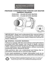
THEORY OF OPERATION
The Fuel System: The gas supply attaches to the heater by a
minimum 3/4 inch i.d. hose or flexible connector. User must supply
hose or flexible connector. The length should be no more than 10
feet long. The natural gas moves through the solenoid valve and the
internal regulator and out the nozzle.
The Air System: The motor turns the fan. The fan pushes air into and
around the combustion chamber. This air is heated and provides a
stream of clean, hot air.
The Ignition System: The direct spark ignitor (DSI) sends voltage
to the ignitor. The ignitor ignites the fuel and air mixture.
The Safety Control System: This system causes the heater to shut
down if the flame goes out.
Air For Combustion
And Heating
Fuel
Combustion
Chamber
DSI
Ignitor
Figure 2 - Cross Section Operational View
Clean
Heated
Air Out
(Front)
Cool Air
In (Back)
Fan
Motor
On/Off
Switch
Solenoid Valve
Nozzle
Internal
Regulator
Power
Cord
NATURAL GAS SUPPLY
The user must furnish the natural gas supply and the connections to
the heater.
Regulate the natural gas supply down from a minimum 5 inches
water column to a maximum of 1/2 psi. The natural gas supply
capacity should be able to supply a minimum of 150 cubic feet of gas
at pressure for each heater connected to the system.
Consult your natural gas supplier for proper sizing of the natural gas
supply lines.
Follow all local ordinances and codes. In the absence of local
ordinances and codes, refer to the National Fuel Gas Code Hand-
book, NFPA54/ANSI Z223.1 and the Natural gas Installation Code,
CAN/CGA B149.1.
WARNING: Follow the minimum fresh, outside air
ventilation requirements. If proper fresh, outside air
ventilation is not provided, carbon monoxide poison-
ing can occur. Provide proper fresh, outside air ven-
tilation before running heater.
VENTILATION
Provide a fresh air opening of at least three square feet for each
100,000 Btu/Hr rating. Provide extra fresh air if more heaters are
being used.

103887-01C
4
For more information, visit www.desatech.com
For more information, visit www.desatech.com
WARNING: Test all gas piping and connections
for leaks after installing or servicing. Never use an
open flame to check for a leak. Apply a mixture of
liquid soap and water to all joints. Bubbles forming
show a leak. Correct all leaks at once.
1. Provide natural gas supply system.
2. Install plumbing to a low pressure natural gas source. The
source must be regulated to a maximum 1/2 psi. The plumbing
must be a minimum 3/4 inch i.d. hose or flexible connector
not over 10 feet long.
3. Connect the hose to the heater at the 1/2 inch SAE flare fitting
at the inlet.
4. Open natural gas supply valve slowly.
5. Check all connections for leaks.
6. Close natural gas supply valve.
INSTALLATION
WARNING: Review and understand the warnings
in the
Safety Information
section, page 2. They are
needed to safely operate this heater. Follow all local
codes when using this heater.
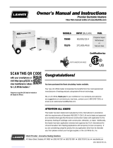
Figure 3 - Hose and Inlet Connector
Hose (not
included)
Inlet
Connector
TO START HEATER
1. Follow all installation, ventilation and safety information.
2. Locate heater on stable and level surface. Make sure strong
drafts do not blow into front or rear of heater.
3. Plug power cord of heater into a three-prong, grounded exten-
sion cord. Extension cord must be at least six feet long. Exten-
sion cord must be UL listed.
Extension Cord Size Requirement
Up to 50 feet long, use 18 AWG rated cord.
51 to 100 feet long, use 16 AWG rated cord.
101 to 200 feet long, use 14 AWG rated cord.
4. Plug extension cord into a 120 volt/60 hertz, three-hole,
grounded outlet.
5. Open natural gas supply valve slowly.
6. Turn thermostat control knob fully counterclockwise to the
"COOLER" position. Turn ON/OFF switch to the ON posi-
tion. Turn thermostat control knob slowly clockwise until elec-
tric motor and fan begin to run. Heater will start in approxi-
mately 3 seconds. Adjust thermostat control knob to WARMER
or COOLER setting as needed.
Note:
If heater does not start after 3 seconds, the ignition con-
trol will automatically attempt to start heater one time. If heater
fails to start on this attempt, the safety control will "lock out"
and no further automatic restarts will be attempted. This could
occur if air remains in fuel line. If heater fails to start on this
attempt, turn ON/OFF switch to OFF position. Wait ten sec-
onds for safety control to reset, then turn ON/OFF switch back
to ON position and try to start heater again.
7. Thermostat Operation Only: During normal thermostat op-
eration, heater will cycle off when air temperature rises to ther-
mostat setting. When air temperature drops sufficiently below
thermostat setting, the electric motor and fan will begin to run.
After 15 to 60 seconds, heater burner should automatically
ignite and provide heat to maintain temperature setting.
TO STOP HEATER
1. Tightly close natural gas supply valve.
2. Wait a few seconds. Heater will burn gas left in supply hoses.
3. Turn on/off switch to the OFF position.
4. Unplug heater.
OPERATION
WARNING: Review and understand the warnings
in the
Safety Information
section, page 2. They are
needed to safely operate this heater. Follow all local
codes when using this heater.
INSTALLATION
OPERATION
To Start Heater
To Stop Heater

103887-01C
5
5
For more information, visit www.desatech.com
For more information, visit www.desatech.com
STORAGE
CAUTION: Disconnect heater from natural gas
supply.
MAINTENANCE
WARNING: Never service heater while it is plugged
in, connected to gas supply, operating, or hot. Severe
burns and electrical shock can occur.
1. Keep heater clean. Clean heater annually or as needed to re-
move dust and debris. If heater is dirty or dusty, clean heater
with a damp cloth.
2. Inspect heater before each use. Check connections for leaks.
Apply mixture of liquid soap and water to connections. Bubbles
forming show a leak. Correct all leaks at once.
3. Have heater inspected yearly by a qualified service agency.
4. Keep inside of heater free from combustible and foreign objects.
1. Place plastic cover cap over brass fitting on inlet connector.
2. Store in dry, clean, and safe place. Do not store hose inside
heater combustion chamber.
3. When taking heater out of storage, always check inside of
heater. Insects and small animals may place foreign objects in
heater. Keep inside of heater free from combustible and for-
eign objects.
STORAGE
MAINTENANCE
SERVICE PROCEDURES
Upper Shell Removal
Fan
Ignitor
FAN
IMPORTANT:
Remove fan from motor shaft before removing
motor from heater. The weight of the motor resting on the fan could
damage the fan pitch.
1. Remove upper shell (see column 1).
2. Use 1/8" hex wrench to loosen setscrew which holds fan to
motor shaft.
3. Slip fan off motor shaft.
4. Clean fan using soft cloth moistened with kerosene or solvent.
5. Dry fan thoroughly.
6. Replace fan on motor shaft. Make sure setscrew is touching
back of flat surface on motor shaft (see Figure 6).
7. Place setscrew on flat of shaft. Tighten setscrew firmly (40-50
inch-pounds).
8. Replace fan guard and upper shell.
SERVICE PROCEDURES
UPPER SHELL REMOVAL
1. Remove screws along each side of heater using 5/16" nut-driver.
These screws attach upper and lower shells together.
2. Lift or slide upper shell off.
3. Remove fan guard.
WARNING: Never service heater while it is plugged
in, connected to gas supply, operating, or hot. Severe
burns and electrical shock can occur.
Figure 4 - Upper Shell Removal
FAN CROSS SECTION LP-PFA/P 013
Fan
Hub
Setscrew
Motor
Shaft
FAN LP-PFA/P 023
Figure 5 - Fan, Motor Shaft, and Setscrew Location
Motor
Shaft
Fan
Setscrew
Figure 6 - Fan Cross Section
IGNITOR
1. Make sure gap between ignitor electrode and burner nozzle is
.13⁄.15". Access ignitor electrode from inside combustion cham-
ber. No other maintenance is needed for ignitor.

103887-01C
6
For more information, visit www.desatech.com
For more information, visit www.desatech.com
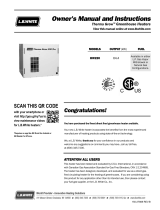
ILLUSTRATED PARTS
BREAKDOWN
BNG150T
33
2
1
31
12
26
43
9
32
10
11
38
20
21
6
7
6
5
3
37
34
Note: Screws are standard hardware items
28
7
15
51
27
8
14
36
48
39
4
8
13
25
23
16
47
49
20
35
22
24
18
19
41
44
45
46
44
40
50
17
29
30
42
45
52
53
M
A
X
I
T
R
O
L
¤
ILLUSTRATED PARTS BREAKDOWN
BNG150T

103887-01C
7
7
For more information, visit www.desatech.com
For more information, visit www.desatech.com
KEY PART
NO. NUMBER DESCRIPTION QTY.
PARTS LIST
This list contains replaceable parts used in your heater. When
ordering parts, follow the instructions listed under Replacement
Parts on page 8 of this manual.
BNG150T
KEY PART
NO. NUMBER DESCRIPTION QTY.
1 098511-114 Upper Shell 1
2 100647-01 Screw, #10-16 x 1/2" 8
3 098512-53 Combustion Chamber Kit 1
4 103891-01 Nozzle 1
5 103934-01 Ignitor 1
6 M11084-38 Screw, #8-18 x 3/8" 2
7 099334-03 Fuel Tube Kit 1
8 097806-02 Ignitor Cable 1
9 M51108-01 Heat Shield 1
10 M51153-01 Fan 1
11 103404-01 Motor 1
12 097776-01 Universal Bushing 1
13 078978-01 Sleeve Cap 1
14 103401-01 Male Connector 1
15 103403-01 Solenoid Valve 1
16 097966-12AA Base 1
17 078896-02 Washer, Baffle 1
18 M12461-7 Screw, #6-32 x 1" 2
19 099432-01 Hex Nut, #6-32 2
20 M11084-27 Screw, #10-16 x 1/2" 10
21 M50104-05 Shorty Bushing 1
22 M50104-01 Shorty Bushing 1
23 101481-05 Thermal Limit Switch 1
24 097968-05 Screw, #4-40 x 1/2" 2
25 097384-04 Hex Nut, #4-40 Captive Washer 2
26 098511-129 Lower Shell 1
27 097965-02AA Side Cover 1
28 098226-01 On/Off Switch 1
29 079010-38 Wire Assembly 1
30 103406-01 Regulator 1
31 M51104-01 Handle 1
32 M11084-29 Screw, #10-16 x 3/4" 2
33 097964-03AA Fan Guard 1
34 101206-01
Motor & Relay Support Brkt Assy
1
35 M11143-1 Strain Relief Bushing 1
36 098219-17 Power Cord 1
37 M50631 Rubber Bumper 2
38 NTC-4C Lock Nut 2
39 099157-01 Break Mandrell Rivet, 3/16" 1
40 099125-01 Terminal Board 1
41 M12461-25 Screw, #10-32 x 1/4" 2
42 103407-01 Fitting, Union 1/2 NPT to 1/2 NPT 1
43 M11271-8 Clip Nut 8
44 101480-10 High Temperature Wire Assy 1
45 101480-11 High Temperature Wire Assy 1
46 098276-01 Plug 1/8 NPTF Hex 1
47 M10908-1 Screw Hex TPG “F” 6-32 x .25 2
48 097657-03 Built-in Thermostat 1
49 104905-01 Thermostat Knob 1
50 103400-02 Screw, Baffle 1
51 M51605-02 DSI Control No. 2003-19 1
52 M51605-05 DSI Control No. 2003-45 1
53 110267-01
DSI Wire Harness (2003-45 Only)
1
PARTS AVAILABLE—NOT SHOWN
M16841-20 Wire Assembly (2003-45 Only) 1
103402-03 Wiring Decal (2003-45 Only) 1
103402-01 Wiring Decal (2003-19 Only) 1
079231-01 Service Center List 1
097940-09 Tradename Decal 2
103886-01 General Information Decal 1
099504-01 Warning Decal 2
103021-01 Thermostat Decal 1
103889-01 NG Warning Decal 1
PARTS LIST
BNG150T

103887-01C
8
For more information, visit www.desatech.com
For more information, visit www.desatech.com
SPECIFICATIONS
Input Rating (Btu/Hr) 150,000
Fuel Natural Gas Only
Fuel Consumption 146 Cubic Feet/Hour
Supply Pressure To Heater Min: 5"WC Max: 1/2 psi
Internal Regulator Outlet Pressure 4" WC (Factory Preset)
Manifold Pressure 5" WC
Hot Air Output (CFM Approx) 550
Motor 3,430 RPM, 1/8 HP
Electric Input 120 V/60 Hz
Amperage 2.2
Ignition Direct Spark, Interrupted Type
Ignitor Gap (Inches) .13/.15
Weight (Pounds) Heater: 24 Shipping: 35
Size - L x W x H (Inches) 36
1
/4 x 14
1
/2 x 20
WIRING DIAGRAMS
Electrical Connection Diagram
Electrical Ladder Diagram
TECHNICAL SERVICE
You may have further questions about installation, operation, or
troubleshooting. If so, contact DESA International’s Technical
Service Department at 1-866-672-6040. When calling please have
your model and serial numbers of your heater ready.
You can also visit DESA International’s technical services web site
at www.desatech.com.
REPLACEMENT PARTS
PARTS UNDER WARRANTY
Contact authorized dealers of this product. If they can’t supply
original replacement part(s), either contact your nearest Parts Cen-
tral or call DESA International’s Technical Service Department at
1-866-672-6040. When calling DESA International, have ready:
• your name
• your address
• model and serial numbers of your heater
• how heater was malfunctioning
• purchase date
In most cases, we will ask you to return the part to the factory.
PARTS NOT UNDER WARRANTY
Contact authorized dealers of this product. If they can’t supply
original replacement part(s), either contact your nearest Parts Cen-
tral or call DESA International at 1-866-672-6040. When calling
DESA International, have ready:
• model number of your heater
• the replacement part number
WARNING: Use only original replacement parts.
This heater must use design-specific parts. Do not
substitute or use generic parts. Improper replace-
ment parts could cause serious or fatal injuries. This
will also protect your warranty coverage for parts
replaced under warranty.
SPECIFICATIONS
TECHNICAL SERVICE
REPLACEMENT PARTS
WIRING DIAGRAMS
Line
Neutral
Green or
Green/Yellow
Black
White
Green
Black
White
Motor
Blue
Blue
Blue
Green
Black
White
Orange
Ignitor
Solenoid
Valve
Automatic
Ignition
System
G V VR ACR AC
Position of
Leads May
Vary
T
Orange
Green
Automatic
Ignition
System
G V VR ACR AC
Position of
Leads May
Vary
Blue
Blue
White
White
Black
Blue
Insulated
Connector
Solenoid
Valve
Black
Motor
Power Cord
120 VAC
On/Off
Switch
Black
High Temp
Switch
Black
Thermostat
White
Green
Green
T
Black
Black
Black

103887-01C
9
9
For more information, visit www.desatech.com
For more information, visit www.desatech.com
1. Who will heater be used by? ❍ Individual ❍ Business
2. Will you use your heater in more than one location? ❍ Yes ❍ No
3. Where will the product be used? (You may select more than one.) ❍ Workshop ❍ Workshop ❍ Barn ❍ Residential Construction
❍ Commercial Construction ❍ Garage ❍ Factory ❍ Recreation ❍ Warehouse ❍ Utility Shed/Outbuilding
❍ Other ______________________________ (Specify)
4. Cost of product (excluding sales tax)? $________________________________
5. Maintenance/service work will be performed by: ❍ Self ❍ Service Center ❍ Other ___________________________________
6. If you bought this product yourself, did you plan to purchase this type of product before going into the store? ❍ Yes ❍ No
7. Type of store where product was purchased? ❍ Hardware ❍ Propane Dealer ❍ Natural Gas/Utility Co. ❍ Home Center or Builder's Supply
❍ Farm/Ag. Supply ❍ Auto Parts ❍ Warehouse Club ❍ Industrial/Contractor Supply ❍ Rental Store
❍ Discount Store ❍ HVAC Dealer ❍ Other _________________________________________________
8. What is your primary source of heat? ❍ Propane (LP Gas) ❍ Natural Gas ❍ Kerosene ❍ Diesel ❍ Electric ❍ Other________________
9. What motivated you to buy this product? ❍ Sudden Cold Weather ❍ Replace Older Model ❍ D.I.Y. Home Project ❍ Emergency Back-Up Heat
❍ Heater on Sale ❍ Construction Project ❍ Hard to Heat Location ❍ Other ________________________________
10. How did you learn about this product brand? ❍ Advertisement ❍ Relative or Friend ❍ Co-Worker ❍ Store Representative
❍ Store Display ❍ Previously Owned a Heater ❍ Other _________________________________________________(Specify)
11. What other brands did you consider? ❍ None ❍ Master ❍ Remington ❍ All-Pro ❍ Dayton ❍ Universal ❍ Mr. Heater ❍ L.B. White Tradesman
❍ John Deere ❍ Dyna-Glo ❍ Dura-Heat ❍ Paulin ❍ Coleman ❍ Vogelzang American ❍ Other ___________________________________
12. Who selected the product? ❍ Male ❍ Female ❍ Both
13. Level of Education of Purchaser: ❍ High School ❍ Vocation/Technical School ❍ Some College ❍ Completed College ❍ Graduate School
14. Age of Purchaser: ❍ Under 20 ❍ 20 - 29 ❍ 30 - 39 ❍ 40 - 49 ❍ 50 - 59 ❍ 60 or Over
15. Buyer's total annual household income: ❍ Under $19,999 ❍ $20,000 to $34,999 ❍ $35,000 to $49,999
❍ $50,000 to $74,999 ❍ $75,000 to $99,999 ❍ $100,000 and Over
16. What is the population of your area? ❍ Under 10,000 ❍ 10,000 to 25,000 ❍ 25,000 to 50,000 ❍ 50,000 to 100,000
❍ 100,000 to 250,000 ❍ Over 250,000
17. Store where product was purchased:
Name: ______________________________________ City: _____________________________________ State: __________
18. In choosing this product, how important were the following:
Availability
Price
Brand Name
Overall Quality
Heat Output (Btu/Hr Rating)
Variable Heat Output (Btu/Hr)
Made in USA
Warranty
Local Service
Value for Price
19. This question will allow us to better understand the demographic profile of our customers. Which of the following best describes you? (not required)
❍ African American ❍ Asian American ❍ Mexican ❍ Puerto Rican ❍ Cuban ❍ Other Hispanic ❍ White ❍ Other ___________________
Brand: (Reddy Heater, Master, Remington, etc.)
Model: (R60, HD15, etc.)
Date Purchased:
Note:
Keep receipt for warranty verification.
Serial Number: 7 or 9 digit number located on product or identification tag.
First Name: Last Name:
Address:
City: State: Zip: Country:
Phone: ( ) - E-Mail:
OWNER'S REGISTRATION FORM
Please answer the following questions to register your product with DESA International:
Complete registration form and mail or complete on-line registration at www.desatech.com within 30 days after purchase.
Not Somewhat Very
❍
❍
❍
❍
❍
❍
❍
❍
❍
❍
❍
❍
❍
❍
❍
❍
❍
❍
❍
❍
❍
❍
❍
❍
❍
❍
❍
❍
❍
❍
Not Somewhat Very
❍
❍
❍
❍
❍
❍
❍
❍
❍
❍
❍
❍
❍
❍
❍
❍
❍
❍
❍
❍
❍
❍
❍
❍
❍
❍
❍
Size
Prior Brand Experience
Built-In Thermostat
Ease of Operation
Special Features
Salesperson's Recommendation
Friend/Relative's Recommendation
Portability
Quiet Operation

2701 Industrial Drive
P.O. Box 90004
Bowling Green, KY 42102-9004
Postage
Required
TM
TAPE
TAPE

k
l
s
u
i
e
j
l
b
o
e
k
l
h
i
k
o
k
l
e
,
,
;
l
o
g
;
e
;
;
p
d
l
;
l
k
l
s
u
i
e
j
l
b
o
e
;
e
;
;
p
d
l
;
l
k
l
s
u
i
e
j
l
b
o
e
k
l
h
i
k
o
k
l
e
,
,
;
l
o
g
;
e
;
;
p
d
l
;
l
k
l
s
u
i
e
j
l
b
o
e
k
l
h
i
k
o
k
l
e
,
,
;
l
o
g
;
e
;
;
p
d
l
;
l
k
l
s
u
i
e
j
l
b
o
e
k
l
h
i
k
o
k
l
e
,
,
;
l
o
g
;
e
;
;
p
d
l
;
l
k
l
s
u
i
e
j
l
b
o
e
k
l
h
i
k
o
k
l
e
,
,
;
l
o
g
;
e
;
;
p
d
l
;
l
k
l
s
u
i
e
j
l
b
o
e
k
l
h
i
k
o
k
l
e
,
,
;
l
o
g
;
e
;
;
p
d
l
;
l
k
l
s
u
i
e
j
l
b
o
e
k
l
h
i
k
o
k
l
e
,
,
;
l
o
g
;
e
;
;
p
d
l
;
l
k
l
s
u
i
e
j
l
b
o
e
k
l
h
i
k
o
k
l
e
,
,
;
l
o
g
;
e
;
;
p
d
l
;
l
k
l
s
u
i
e
j
l
b
o
e
k
l
h
i
k
o
k
l
e
,
,
;
l
o
g
;
e
;
;
p
d
l
;
l
k
l
s
u
i
e
j
l
b
o
e
k
l
h
i
k
o
k
l
e
,
,
;
l
o
g
;
e
;
;
p
d
l
;
l
k
l
s
u
i
e
j
l
b
o
e
k
l
h
i
k
o
k
l
e
,
,
;
l
o
g
;
e
;
;
p
d
l
;
l
k
l
s
u
i
e
j
l
b
o
e
k
l
h
i
k
o
k
l
e
,
,
;
l
o
g
;
e
;
;
p
d
l
;
l
k
l
s
u
i
e
j
l
b
o
e
k
l
h
i
k
o
k
l
e
,
,
;
l
o
g
;
e
;
;
p
d
l
;
l
k
l
s
u
i
e
j
l
b
o
e
k
l
h
i
k
o
k
l
e
,
,
;
l
o
g
;
e
;
;
p
d
l
;
l
k
l
s
u
i
e
j
l
b
o
e
k
l
h
i
k
o
k
l
e
,
,
;
l
o
g
;
e
;
;
p
d
l
;
l
W
A
R
N
IN
G
k
l
s
u
i
e
j
l
b
o
e
k
l
h
i
k
o
k
l
e
,
,
;
l
o
g
;
e
;
;
p
d
l
;
l
k
l
s
u
i
e
j
l
b
o
e
k
l
h
i
;
e
;
;
p
d
l
;
l
k
l
s
u
i
e
j
l
b
o
e
k
l
h
i
k
o
k
l
e
,
,
;
l
o
g
;
e
;
;
p
d
l
;
l
k
l
s
u
i
e
j
l
b
o
e
k
l
h
i
k
o
k
l
e
,
,
;
l
o
g
;
e
;
;
p
d
l
;
l
k
l
s
u
i
e
j
l
b
o
e
k
l
h
i
k
o
k
l
e
,
,
;
l
o
g
;
e
;
;
p
d
l
;
l
k
l
s
u
i
e
j
l
b
o
e
k
l
h
i
k
o
k
l
e
,
,
;
l
o
g
;
e
;
;
p
d
l
;
l
k
l
s
u
i
e
j
l
b
o
e
k
l
h
i
k
o
k
l
e
,
,
;
l
o
g
;
e
;
;
p
d
l
;
l
k
l
s
u
i
e
j
l
b
o
e
k
l
h
i
k
o
k
l
e
,
,
;
l
o
g
;
e
;
;
p
d
l
;
l
k
l
s
u
i
e
j
l
b
o
e
k
l
h
i
k
o
k
l
e
,
,
;
l
o
g
;
e
;
;
p
d
l
;
l
k
l
s
u
i
e
j
l
b
o
e
k
l
h
i
k
o
k
l
e
,
,
;
l
o
g
;
e
;
;
p
d
l
;
l
k
l
s
u
i
e
j
l
b
o
e
k
l
h
i
k
o
k
l
e
,
,
;
l
o
g
;
e
;
;
p
d
l
;
l
k
l
s
u
i
e
j
l
b
o
e
k
l
h
i
k
o
k
l
e
,
,
;
l
o
g
;
e
;
;
p
d
l
;
l
k
l
s
u
i
e
j
l
b
o
e
k
l
h
i
k
o
k
l
e
,
,
;
l
o
g
;
e
;
;
p
d
l
;
l
k
l
s
u
i
e
j
l
b
o
e
k
l
h
i
k
o
k
l
e
,
,
;
l
o
g
;
e
;
;
p
d
l
;
l
k
l
s
u
i
e
j
l
b
o
e
k
l
h
i
k
o
k
l
e
,
,
;
l
o
g
;
e
;
;
p
d
l
;
l
k
l
s
u
i
e
j
l
b
o
e
k
l
h
i
k
o
k
l
e
,
,
;
l
o
g
;
e
;
;
p
d
l
;
l
WARNING
PROPANE/LP FORCED AIR HEATERS
PROPANE/LP TANK TOP HEATERS
PROPANE/LP AND NATURAL
GAS GARAGE HEATERS
PROPANE/LP CONVECTION HEATERS
PORTABLE KEROSENE/DIESEL
FORCED AIR HEATERS
PROPANE/LP
PATIO HEATERS
PROPANE/LP AND NATURAL
GAS CHIMENEAS
OTHER OUTDOOR HEATING PRODUCTS

103887-01C
12
For more information, visit www.desatech.com
For more information, visit www.desatech.com
WARRANTY AND REPAIR SERVICE
LIMITED WARRANTY
DESA International warrants this product and any parts thereof, to be free from defects in materials and workmanship for one (1) year from the date
of first purchase when operated and maintained in accordance with instructions. This warranty is extended only to the original retail purchaser, when
proof of purchase is provided.
This warranty covers only the cost of parts and labor required to restore the product to proper operating condition. Transportation and incidental
costs associated with warranty repairs are not reimbursable under this warranty.
Warranty service is available only through authorized dealers and service centers.
This warranty does not cover defects resulting from misuse, abuse, negligence, accidents, lack of proper maintenance, normal wear, alteration,
modification, tampering, contaminated fuels, repair using improper parts, or repair by anyone other than an authorized dealer or service center.
Routine maintenance is the responsibility of the owner.
THIS EXPRESS WARRANTY IS GIVEN IN LIEU OF ANY OTHER WARRANTY EITHER EXPRESSED OR IMPLIED, INCLUDING
WARRANTIES OF MERCHANTABILITY AND FITNESS FOR A PARTICULAR PURPOSE.
DESA International assumes no responsibility for indirect, incidental or consequential damages. Some states do not allow the exclusion or limitation
of incidental or consequential damages, or limitations or exclusions may not apply to you. This Limited Warranty gives you specific legal rights
and you may also have other rights which vary from state to state.
KEEP THIS WARRANTY
103887-01
Rev. D
05/02
We reserve the right to amend these specifications at any time without notice. The only warranty applicable is our standard written warranty. We
make no other warranty, expressed or implied.
WARRANTY SERVICE
Should your heater require service, return it to your nearest authorized service center. Proof of purchase must be presented with the heater. The heater
will be inspected. A defect may be caused by faulty materials or workmanship. If so, DESA International will repair or replace the heater without charge.
REPAIR SERVICE
Return your heater to your nearest authorized service center. Repairs not covered by the warranty will be billed at standard prices. Each Service Center
is independently owned and operated. We reserve the right to amend these specifications at any time without notice. When writing, always include model
number and serial number. For information, write:
Model
Serial No.
Date of Purchase
2701 Industrial Drive
P.O. Box 90004
Bowling Green, KY 42102-9004
ATTN: Customer Service Department
NOT A UPC
103887 01
TM
/