
®
INSTALLATION
FX82051 Unmanaged
Ethernet Switch
Five 10BASE-T/100BASE-TX Ports
and One 100BASE-FX Fiber Port
C2622M (2/07)

2 C2622M (2/07)
Contents
Important Safety Instructions . . . . . . . . . . . . . . . . . . . . . . . . . . . . . . . . . . . . . . . . . . . . . . . . . . . 3
Regulatory Notices . . . . . . . . . . . . . . . . . . . . . . . . . . . . . . . . . . . . . . . . . . . . . . . . . . . . . . . . . . . 5
Product Overview . . . . . . . . . . . . . . . . . . . . . . . . . . . . . . . . . . . . . . . . . . . . . . . . . . . . . . . . . . . . 6
Description . . . . . . . . . . . . . . . . . . . . . . . . . . . . . . . . . . . . . . . . . . . . . . . . . . . . . . . . . . . . 6
Models. . . . . . . . . . . . . . . . . . . . . . . . . . . . . . . . . . . . . . . . . . . . . . . . . . . . . . . . . . . . . . . . 7
Optional Accessories. . . . . . . . . . . . . . . . . . . . . . . . . . . . . . . . . . . . . . . . . . . . . . . . 7
Front Panel. . . . . . . . . . . . . . . . . . . . . . . . . . . . . . . . . . . . . . . . . . . . . . . . . . . . . . . . . . . . . 8
Rear Panel . . . . . . . . . . . . . . . . . . . . . . . . . . . . . . . . . . . . . . . . . . . . . . . . . . . . . . . . . . . . . 9
Installation . . . . . . . . . . . . . . . . . . . . . . . . . . . . . . . . . . . . . . . . . . . . . . . . . . . . . . . . . . . . . . . . 10
Package Contents . . . . . . . . . . . . . . . . . . . . . . . . . . . . . . . . . . . . . . . . . . . . . . . . . . . . . . 10
Setting 10BASE-T/100BASE-TX Port Modes of Operation. . . . . . . . . . . . . . . . . . . . . . . 10
Mounting . . . . . . . . . . . . . . . . . . . . . . . . . . . . . . . . . . . . . . . . . . . . . . . . . . . . . . . . . . . . . 13
Mounting the FX82051 Module into a Rack . . . . . . . . . . . . . . . . . . . . . . . . . . . . . 13
Mounting the FX82051 Module to a Wall. . . . . . . . . . . . . . . . . . . . . . . . . . . . . . . 13
Connections. . . . . . . . . . . . . . . . . . . . . . . . . . . . . . . . . . . . . . . . . . . . . . . . . . . . . . . . . . . 15
Troubleshooting . . . . . . . . . . . . . . . . . . . . . . . . . . . . . . . . . . . . . . . . . . . . . . . . . . . . . . . . . . . . 17
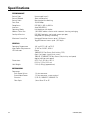
Specifications . . . . . . . . . . . . . . . . . . . . . . . . . . . . . . . . . . . . . . . . . . . . . . . . . . . . . . . . . . . . . . 24
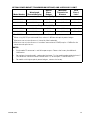
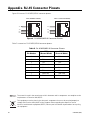
Appendix. RJ-45 Connector Pinouts. . . . . . . . . . . . . . . . . . . . . . . . . . . . . . . . . . . . . . . . . . . . . 26
List of Illustrations
1 FX82051 Point-to-Point Application . . . . . . . . . . . . . . . . . . . . . . . . . . . . . . . . . . . . . . . . . 6
2 Front Panel of FX82051 Module . . . . . . . . . . . . . . . . . . . . . . . . . . . . . . . . . . . . . . . . . . . . 8
3 Rear Panel of FX82051 Module (SC Fiber Connector Shown) . . . . . . . . . . . . . . . . . . . . . 9
4 TX Mode Switches for 10BASE-T/100BASE-TX Ports 1-5 . . . . . . . . . . . . . . . . . . . . . . . 10
5 Mounting the FX82051 Module Using the Wall Clip . . . . . . . . . . . . . . . . . . . . . . . . . . . 14
6 FX82051 Module Connections . . . . . . . . . . . . . . . . . . . . . . . . . . . . . . . . . . . . . . . . . . . . 15
7 Fiber Port Connections in Point-to-Point Application . . . . . . . . . . . . . . . . . . . . . . . . . . . 16
8 RJ-45 MDI/MDI-X Connector Pinouts. . . . . . . . . . . . . . . . . . . . . . . . . . . . . . . . . . . . . . . 26
List of Tables
A TX Mode Switch Settings . . . . . . . . . . . . . . . . . . . . . . . . . . . . . . . . . . . . . . . . . . . . . . . . 12
B Troubleshooting with Front-Panel Indicators . . . . . . . . . . . . . . . . . . . . . . . . . . . . . . . . . 17
C Troubleshooting with Rear-Panel Indicators. . . . . . . . . . . . . . . . . . . . . . . . . . . . . . . . . . 19
D RJ-45 MDI/MDI-X Connector Pinouts. . . . . . . . . . . . . . . . . . . . . . . . . . . . . . . . . . . . . . . 26

C2622M (2/07) 3
Important Safety Instructions
1. Read these instructions.
2. Keep these instructions.
3. Heed all warnings.
4. Follow all instructions.
5. Do not use this apparatus near water.
6. Clean only with dry cloth.
7. Do not block any ventilation openings. Install in accordance with the manufacturer’s
instructions.
8. Do not install near any heat sources such as radiators, heat registers, stoves, or other
apparatus (including amplifiers) that produce heat.
9. Do not defeat the safety purpose of the polarized or grounding-type plug. A polarized plug has
two blades with one wider than the other. A grounding plug has two blades and a third
grounding prong. The wide blade or the third prong are provided for your safety. If the provided
plug does not fit into your outlet consult an electrician for replacement of the obsolete outlet.
10. Protect the power cord from being walked on or pinched particularly at plugs, convenience
receptacles, and the points where they exit from the apparatus.
11. Only use attachments/accessories specified by the manufacturer.
12. Use only with the cart, stand, tripod, bracket, or table specified by the manufacturer, or sold
with the apparatus. When a cart is used, use caution when moving the cart/apparatus
combination to avoid injury from tip-over.
13. Refer all servicing to qualified service personnel. Servicing is required when the apparatus has
been damaged in any way, such as power-supply cord or plug is damaged, liquid has been
spilled or objects have fallen into the apparatus, the apparatus has been exposed to rain or
moisture, does not operate normally, or has been dropped.
14. Apparatus shall not be exposed to dripping or splashing and that no objects filled with liquids,
such as vases shall be placed on the apparatus.
15. WARNING: To reduce the risk of fire or electric shock, do not expose this apparatus to rain or
moisture.
16. Installation should be done only by qualified personnel and conform to all local codes.
17. Use only installation methods and materials capable of supporting four times the maximum
specified load.
18. A CCC-approved power cord must be used to power this equipment when used in China.
19. CAUTION: These servicing instructions are for use by qualified service personnel only. To
reduce the risk of electric shock do not perform any servicing other than that contained in the
operating instructions unless you are qualified to do so.

4 C2622M (2/07)
The product and/or manual may bear the following marks:
This symbol indicates that dangerous voltage
constituting a risk of electric shock is present
within this unit.
This symbol indicates that there are important
operating and maintenance instructions in the
literature accompanying this unit.
CAUTION:
RISK OF ELECTRIC SHOCK.
DO NOT OPEN.

C2622M (2/07) 5
Regulatory Notices
This device complies with Part 15 of the FCC Rules. Operation is subject to the following two
conditions: (1) this device may not cause harmful interference, and (2) this device must accept any
interference received, including interference that may cause undesired operation.
RADIO AND TELEVISION INTERFERENCE
This equipment has been tested and found to comply with the limits of a Class A digital device,
pursuant to Part 15 of the FCC Rules. These limits are designed to provide reasonable protection
against harmful interference when the equipment is operated in a commercial environment. This
equipment generates, uses, and can radiate radio frequency energy and, if not installed and used in
accordance with the instruction manual, may cause harmful interference to radio communications.
Operation of this equipment in a residential area is likely to cause harmful interference in which case
the user will be required to correct the interference at his own expense.
Changes and Modifications not expressly approved by the manufacturer or registrant of this
equipment can void your authority to operate this equipment under Federal Communications
Commission’s rules.
This Class A digital apparatus complies with Canadian ICES-003.
Cet appareil numérique de la classe A est conforme à la norme NMB-003 du Canada.

6 C2622M (2/07)
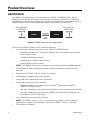
Product Overview
DESCRIPTION
The FX82051 unmanaged Ethernet switch provides five 10BASE-T/100BASE-TX ports and one
100BASE-FX fiber port for the transport of bidirectional Ethernet data. Two fibers are required to
transport bidirectional data over the fiber port. Available in multimode and single-mode versions, the
FX82051 Ethernet switch is designed for point-to-point applications (refer to Figure 1).
Figure 1. FX82051 Point-to-Point Application
Features of the FX82051 Ethernet switch include the following:
• User-selectable networking functions for each 10BASE-T/100BASE-TX port:
– Autonegotiation between 10 Mbps and 100 Mbps data rates and between full-duplex
and half-duplex modes
– 10 Mbps or 100 Mbps selectable
– Full-duplex or half-duplex mode selectable
– Enabling/disabling of flow control
NOTE: The 100BASE-FX fiber port is automatically forced to full-duplex 100 Mbps operation.
• Auto MDI/MDI-X (Medium Dependent Interface/Medium Dependent Interface Crossover)
operation
• Compliant with IEEE 802.3, 802.3u, and 802.3x standards
• Multimode fiber support for distances up to 6 km
• Single-mode fiber support for distances up to 46 km
• Compatible with other Ethernet equipment:
– 10BASE-T/100BASE-TX compatibility with all Pelco
®
and third-party 10BASE-T/
100BASE-TX Ethernet devices
– Fiber optic compatibility with all Pelco Ethernet devices that use two fibers per fiber port
– Fiber optic compatibility with third-party 100BASE-FX Ethernet devices (applicable to
multimode ST and SC versions only)
• Laser diode for transmission of optical signals
NOTE: The FX82051 switch is a Class 1 laser product that complies with FDA radiation
performance standard 21CFR Subchapter J and with IEC 60825-1 Edition 1.2, 2001-08.
• Environmentally hardened
FX82051
FX82051
FIVE 10/100 Mbps
CONNECTIONS
TWO
FIBERS
FIVE 10/100 Mbps
CONNECTIONS

C2622M (2/07) 7
• Designed to meet NEMA TS 2 and Caltrans traffic signal control equipment standards for
ambient operating temperature, mechanical shock and vibration, humidity with condensation,
high-line/low-line voltage conditions, and transient voltage protection
NOTE: Conformal coating is required for operation in environments with relative humidity
above 95 percent (condensing).
• No performance adjustments required
• 12 VDC or 24 VAC power supply
• Stand-alone and rack-mountable modular design
• LED indicators for monitoring of optic signal/laser status, 100BASE-FX port status including far
end fault indication (FEFI), 10BASE-T/100BASE-TX port status, and operating power
MODELS
The FX82051 module consists of the following series of models:
Multimode Models
*
FX82051MSTR-2 Unmanaged Ethernet switch, five 10BASE-T/100BASE-TX ports, one multimode
ST fiber port, two fibers
FX82051MSCR-2 Unmanaged Ethernet switch, five 10BASE-T/100BASE-TX ports, one multimode
SC fiber port, two fibers
Single-Mode Models
*†
FX82051SSTR-2 Unmanaged Ethernet switch, five 10BASE-T/100BASE-TX ports, one single-
mode ST fiber port, two fibers
FX82051SSCR-2 Unmanaged Ethernet switch, five 10BASE-T/100BASE-TX ports, one single-
mode SC fiber port, two fibers
*
For conformal coated models, replace the first letter F in the model number with the letter C.
The conformal coated version of FX82051MSTR-2, for example, is CX82051MSTR-2.
†
Single-mode FC connector is available upon request. Contact the factory for additional information.
OPTIONAL ACCESSORIES
The following optional accessories are available:
WM5002-3U Wall mount base kit for double-width module
WM5002-3UEXP Wall mount expansion kit for double-width module
RK5000-3U 19-inch rack mount chassis for 14 slots (no power), 3 RUs
RK5000PS-3U 19-inch rack mount chassis for 12 slots with power, 3 RUs
EPS5000-120 External rack power supply, 1 RU, dual 120 W power outputs
RK5001B-3U Blank filler panel, single width
RK5002B-3U Blank filler panel, double width
RK5002-1UEXP Adapter kit that allows a 3 RU double-width fiber module to be used in
RK5000PS-5U rack mount chassis

8 C2622M (2/07)
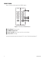
FRONT PANEL
Figure 2 illustrates the front panel of the FX82051 module.
Figure 2. Front Panel of FX82051 Module
For detailed information about the front-panel LEDs, refer to Troubleshooting on page 17.
ì
Reset Button: Restarts the unit
î
100BASE-FX Status LED
ï
Optic Fault LED: Optical signal status/laser status indicator
ñ
Power LED: Pelco badge

C2622M (2/07) 9
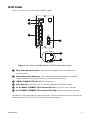
REAR PANEL
Figure 3 illustrates the rear panel of the FX82051 module.
Figure 3. Rear Panel of FX82051 Module (SC Fiber Connector Shown)
For additional information about rear-panel connections, refer to Installation on page 10. For detailed
information about the RJ-45 LEDs, refer to Troubleshooting on page 17.
ì Rack Power/Alarm Connector: 4-pin connector for power/alarm connection of rack-
mounted module
î Stand-Alone Power Connector: 2-pin connector for power connection of stand-alone
module; removable mating connector with screw terminals (not shown)
ï
10BASE-T/100BASE-TX Ports 1-5: RJ-45 connectors
ñ
Fiber Optic Port: Dual-fiber ST or SC connector (dependent on FX82051 model)
ó
RJ-45 10BASE-T/100BASE-TX Port Status LED, Left: Link/activity status indicator
r
RJ-45 10BASE-T/100BASE-TX Port Status LED, Right: Duplex mode/collision indicator

10 C2622M (2/07)
Installation
PACKAGE CONTENTS
The following items are supplied:
1 FX82051 module
1 Regulated switching power supply with four plug adapters (North American, Australian, U.K.,
and European configurations); 100-240 VAC, 50-60 Hz input, 12 VDC output
1 Wall clip with two 4-40 x 0.250-inch Phillips pan head screws with lock washers (for attachment
of single module to wall)
1 FX82051 Unmanaged Ethernet Switch Installation manual
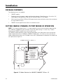
SETTING 10BASE-T/100BASE-TX PORT MODES OF OPERATION
NOTE: As a matter of convenience, it is recommended that you verify the modes of operation for
each 10BASE-T/100BASE-TX port and then change the mode settings—if necessary—before
mounting the FX82051 module into a rack or onto a wall.
The FX82051 module provides various configuration options that allow you to select the desired
modes of operation for each 10BASE-T/100BASE-TX port (ports 1-5). You can select the desired
modes of operation by means of a TX Mode switch that is provided on the bottom of the module for
each port (refer to Figure 4).
Figure 4. TX Mode Switches for 10BASE-T/100BASE-TX Ports 1-5
TX Mode
0. Auto Neg / Dis FC
1. 100 FD / Dis FC
2. 100 HD / Dis FC
3. 10 FD / Dis FC
4. 10 HD / Dis FC
5. Auto Neg / En FC
6. 100 FD / En FC
7. 100 HD / En FC
8. 10 FD / En FC
9. 10 HD / En FC
TX MODE SWITCHES - PORTS 1-5

C2622M (2/07) 11
Using the TX Mode switch for a particular port, you can do the following:
• Enable autonegotiation or select (force) a specific data rate and duplex mode:
– Enabling autonegotiation allows the FX82051 module to automatically negotiate with
the device to which the port is connected for data rate and duplex modes of operation:
10 Mbps or 100 Mbps data rate and half-duplex or full-duplex mode. The highest
common denominator of operational modes is automatically selected.
Autonegotiation is enabled by default.
– If autonegotiation is not desired, you can select a specific data rate and duplex mode:
• Data rate configuration allows you to select 10 Mbps or 100 Mbps.
• Duplex mode configuration allows you to select half-duplex mode or full-duplex
mode.
• Enable or disable flow control. Flow control controls data transmission at the sending device
to avoid overfilling buffers and losing data at the receiving device. When the buffers on the
receiving device are full, a message is sent to the sending device to suspend the transmission
until the data in the buffers has been processed.
NOTE: For time-sensitive data applications (for example, video and audio applications), it is
recommended that flow control be disabled.
Flow control is disabled by default.
With the FX82051 module powered off, set each TX Mode switch to the desired modes of operation.
NOTE: TX Mode configuration must be set when the module is powered off. If you wish to change
a TX Mode switch setting after the module has been powered on, power off the module, change the
TX Mode switch setting, and then power on the module again.
Refer to Table A for TX Mode switch settings and corresponding 10BASE-T/100BASE-TX port modes
of operation. Note that each 10BASE-T/100BASE-TX port operates independently of one another;
therefore, you can set each port to different modes of operation as appropriate.

12 C2622M (2/07)
Table A. TX Mode Switch Settings
TX Mode
Switch Position 10BASE-T/100BASE-TX Modes of Operation
0 Auto Neg/Dis FC: Enables autonegotiation between 10 Mbps and
100 Mbps and between half-duplex and full-duplex modes, disables
flow control (default setting)
1 100 FD/Dis FC: Selects 100 Mbps full-duplex, disables flow control
2 100 HD/DIS FC: Selects 100 Mbps half-duplex, disables flow control
3 10 FD/Dis FC: Selects 10 Mbps full-duplex, disables flow control
4 10 HD/Dis FC: Selects 10 Mbps half-duplex, disables flow control
5 Auto Neg/En FC: Enables autonegotiation between 10 and 100 Mbps
and between half-duplex and full-duplex modes, enables flow control
6 100 FD/En FC: Selects 100 Mbps full-duplex, enables flow control
7 100 HD/En FC: Selects 100 Mbps half-duplex, enables flow control
8 10 FD/En FC: Selects 10 Mbps full-duplex, enables flow control
9 10 HD/En FC: Selects 10 Mbps half-duplex, enables flow control
NOTE: Switch positions 0-4 disable flow control. Positions 5-9 enable flow control.

C2622M (2/07) 13
MOUNTING
The FX82051 module can be mounted into a rack or can be used as a stand-alone module. As a stand-
alone module, the unit can be placed on a desktop or can be mounted to a wall.
NOTE: As a matter of convenience, it is recommended that you set the modes of operation for each
10BASE-T/100BASE-TX port—if required—before mounting the FX82051 module into a rack or onto
a wall. For information about setting the modes of operation, refer to Setting 10BASE-T/100BASE-TX
Port Modes of Operation on page 10.
MOUNTING THE FX82051 MODULE INTO A RACK
The FX82051 module can be installed into an RK5000 Series rack mount chassis, which can be
mounted into an industry-standard 19-inch (48.26 cm) equipment rack. The RK5000 Series rack mount
chassis includes the following models:
• RK5000PS-3U and RK5000-3U: Designed to accommodate fiber optic modules as follows:
– The RK5000PS-3U rack mount chassis provides 12 single-width module slots and a
power supply.
– The RK5000-3U rack mount chassis provides 14 single-width module slots (a power
supply is not included). Power to the modules can be supplied using the optional
external power supply (EPS5000-120).
For additional information, refer to the RK5000PS-3U/RK5000-3U Fiber Rack Mount Chassis
Installation manual.
• RK5000PS-5U: Designed to accommodate Endura
™
modules but can also accommodate fiber
optic modules with the use of the appropriate adapter kit. The RK5002-1UEXP adapter kit is
required for installation of the FX82051 module into the RK5000PS-5U chassis.
For information about the RK5000PS-5U chassis, refer to the RK5000PS-5U Rack Mount Chassis
Installation manual.
NOTE: The FX82051 module is a double-width fiber optic module that occupies two slots in the
RK5000PS-3U, RK5000-3U, and RK5000PS-5U chassis.
MOUNTING THE FX82051 MODULE TO A WALL
The FX82051 module can be mounted to a wall in the following ways:
• Using the supplied wall clip for attachment of a single module to a wall. For installation
instructions, refer to Mounting the FX82051 Module Using the Wall Clip on page 14.
• Using the optional WM5002 wall mount kits, which are designed for mounting of double-
width fiber optic modules. The WM5002-3U base kit allows mounting of a single module to a
wall. The WM5002-3UEXP expansion kit allows mounting of an additional module. It is
recommended that a maximum of one expansion kit be used with the base kit, allowing a
maximum of two double-width modules to be mounted to a wall.
NOTE: The WM5002 wall mount kits can be used with the WM5001 wall mount kits, which are
designed for mounting of single-width fiber optic modules. If mounting a mix of single-width
and double-width modules is desired, it is recommended that a maximum of two single-width
modules and one double-width module be mounted in combination with one another.
For mounting instructions using the wall mount kits, refer to the WM5000 Series Wall Mount
Kit Installation manual.

14 C2622M (2/07)
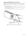
Mounting the FX82051 Module Using the Wall Clip
NOTE: Before mounting the FX82051 module to a wall, ensure that there is adequate space at both
ends for viewing the front-panel LEDs and for making the various rear-panel cable connections.
To attach the FX82051 module to a wall using the supplied wall clip, refer to Figure 5 and do the
following:
1. Using the two vertical or horizontal wall-mounting holes, attach the wall clip to a wall using
two screws (not provided).
2. Slide the module into the clip until the two holes on the bottom of the module align with the
two holes on the lower flange of the clip.
3. Attach the module to the clip using the two Phillips pan head screws provided for the clip.
Figure 5. Mounting the FX82051 Module Using the Wall Clip
UPPER
FLANGE
VERTICAL
MOUNTING HOLE (2)
HORIZONTAL
MOUNTING HOLE (2)
LOWER
FLANGE
WALL CLIP
SCREW, PHILLIPS
PAN HEAD WITH
LOCK WASHER (2)

C2622M (2/07) 15
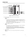
CONNECTIONS
Connections to the FX82051 module are made on the rear panel of the module (refer to Figure 6).
Figure 6. FX82051 Module Connections
As illustrated in Figure 6, FX82051 connections consist of the following:
• Power connection
NOTES:
– A 12 VDC or 24 VAC power supply can be used to power the module when used as a
stand-alone unit. A 12 VDC power supply is provided. If a 24 VAC power supply is used,
the power supply must be a Listed Direct Plug-In Power Unit marked as Class 2 and
rated as 24 VAC, 0.50 A (minimum output).
– In extreme temperature conditions, it is recommended that an industrial-rated outdoor
power supply such as the Pelco WCS1-4 power supply be used.
• 10BASE-T/100BASE-TX connections
NOTES:
– Use Category 5e or a higher category of cable to connect to a 10BASE-T/100BASE-TX
port. Cable length must not exceed 328 feet (100 meters).
– The 10BASE-T/100BASE-TX ports are auto MDI/MDI-X ports; therefore, either a
straight-through or crossover cable can be used. The ports automatically detect the
cable type that is used. Refer to Appendix. RJ-45 Connector Pinouts on page 26 for
RJ-45 MDI/MDI-X pinout information.
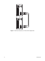
• Fiber connections
NOTE: Refer to Figure 7 for an illustration of fiber port connections in a point-to-point
application.
FIBER OPTIC CABLES
POWER/ALARM
CONNECTION FOR
RACK-MOUNTED MODULE
POWER CONNECTION FOR
STAND-ALONE MODULE
10/100 NETWORK CABLE
10/100 NETWORK CABLE
10/100 NETWORK CABLE
10/100 NETWORK CABLE
10/100 NETWORK CABLE

16 C2622M (2/07)
Figure 7. Fiber Port Connections in Point-to-Point Application

C2622M (2/07) 17
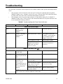
Troubleshooting
LED indicators on the front and rear panels of the FX82051 module allow you to monitor operational
status:
• LED indicators on the front panel (refer to Figure 2) allow you to monitor operating power,
100BASE-FX port status, and optic signal/laser status. Refer to Table B for information about
the front-panel indicators and associated troubleshooting guidelines.
• LED indicators on the rear panel (refer to Figure 3) allow you to monitor RJ-45 10BASE-T/
100BASE-TX port status. Refer to Table C for information about the rear-panel indicators and
associated troubleshooting guidelines.
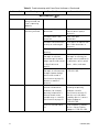
Table B. Troubleshooting with Front-Panel Indicators
Indicator Color Meaning Possible Cause Corrective Action
Power LED (Pelco badge)
Blue Power is being
applied to the
module.
– No action required.
Not lit Power is not being
applied to the
module.
Power connection is faulty. Check power connection.
If module is rack mounted,
reseat module or power
supply as necessary.
Power supply has failed. Replace power supply.
Loss of power occurs due to
tripped circuit breakers,
blown fuses, or faulty
electrical service.
Check circuit breakers, fuses,
or electrical service as
necessary.
100BASE-FX Status LED ( )
Green A fiber link is
established.
— No action required.
Flashing green Data activity is
occurring on the fiber
link.
— No action required.
Red Far end fault indica-
tion (FEFI). The
optical signal
transmitted from this
port is not detected
by the remote link
partner.
Defective fiber transmit port
on local module
Replace local module.
Laser fault on local module
(Optic Fault LED on local
module flashes red).
Refer to the Optic Fault LED
section in this table.
Defective fiber receive port
on remote module
Replace remote module.
NOTE: The Optic Fault LED on the remote module is red. Refer to the Optic Fault
LED section in this table for additional information.
(Continued on next page)

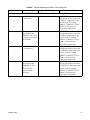
18 C2622M (2/07)
Optic Fault LED ( )
Green The optical signal is
being received and
laser is operating
properly.
— No action required.
Red The optical signal is
not being received.
Remote module is not
powered on.
Check power connections.
Replace power supply if
necessary.
Fiber optic cable is not
connected.
Check fiber optic
connections.
Fiber optic cable connectors
are dirty or are damaged.
Clean, polish, or replace fiber
optic cable connectors as
necessary.
Fiber optic cable is
defective.
Replace cable.
Optical dB losses in the
fiber optic installation
exceed the optical power
budget specification stated
in Specifications on
page 24.
Check for problems with the
fiber optic installation, for
example, excessive dB losses
in connectors, splices, patch
panels, cables, and so on.
Optical dB losses in the
fiber optic installation meet
the optical power budget
specification stated in
Specifications on page 24;
however, a module is
defective.
Contact Product Support at
1-559-292-1981.
Flashing red Laser has shut down. Module is operating in
extreme environmental
conditions; for example,
operating temperature is
below or above recom-
mended range as stated in
Specifications on page 24.
Ensure that module operates
according to operating
conditions stated in
Specifications on page 24,
and then cycle the power.
If problem persists, contact
Product Support at
1-559-292-1981.
Laser has reached end of
life.
Cycle the power. If problem
persists, contact Product
Support at 1-559-292-1981.
(Continued on next page)
Table B. Troubleshooting with Front-Panel Indicators (Continued)
Indicator Color Meaning Possible Cause Corrective Action

C2622M (2/07) 19
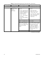
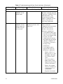
Table C. Troubleshooting with Rear-Panel Indicators
Indicator Color Meaning Possible Cause Corrective Action
RJ-45 10BASE-T/100BASE-TX Port Status LED - Left (Link/Activity)
Amber A 10BASE-T link is
established.
— If 10BASE-T operation is
desired, no action is required.
If 10BASE-T operation is not
desired, refer to Setting
10BASE-T/100BASE-TX Port
Modes of Operation on
page 10 for information.
Flashing amber Data activity is
occurring on the
10BASE-T link; data
is being transmitted
or received.
— If 10BASE-T operation is
desired, no action is required.
If 10BASE-T operation is not
desired, refer to Setting
10BASE-T/100BASE-TX Port
Modes of Operation on
page 10 for information.
Green A 100BASE-TX link
is established.
— If 100BASE-TX operation is
desired, no action is required.
If 100BASE-TX operation is not
desired, refer to Setting
10BASE-T/100BASE-TX Port
Modes of Operation on
page 10 for information.
Flashing green Data activity is
occurring on the
100BASE-TX link;
data is being
transmitted or
received.
— If 100BASE-TX operation is
desired, no action is required.
If 100BASE-TX operation is not
desired, refer to Setting
10BASE-T/100BASE-TX Port
Modes of Operation on
page 10 for information.
(Continued on next page)

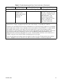
20 C2622M (2/07)
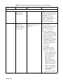
RJ-45 10BASE-T/100BASE-TX Port Status LED - Left (Link/Activity) (Continued)
Not lit A 10BASE-T or
100BASE-TX link
cannot be
established.
A problem may exist with
the cable:
• Cable is not connected
to the module or to the
10BASE-T/100BASE-TX
compatible device.
• Cable is defective.
• Cable is not the proper
cable type.
• Cable is not the proper
length.
Do any of the following as
applicable:
• Connect the cable.
• Replace the cable. Use
Cat5e or higher cable.
• Ensure that cable is proper
length. Cable length must
not exceed 128 feet
(100 meters).
Device connected to the
module is not powered on.
Power on the device connected
to the module.
Duplex mode setting (half-
duplex or full-duplex) does
not match the duplex mode
setting of the remote
module.
Set the duplex mode setting on
modules to match one another
(autonegotiation or forced
half-duplex or full-duplex).
Refer to Setting 10BASE-T/
100BASE-TX Port Modes of
Operation on page 10 for
information.
Port on module is defective. Replace the module
(Continued on next page)
Table C. Troubleshooting with Rear-Panel Indicators (Continued)
Indicator Color Meaning Possible Cause Corrective Action
Page is loading ...
Page is loading ...
Page is loading ...
Page is loading ...
Page is loading ...
Page is loading ...
Page is loading ...
Page is loading ...
-
 1
1
-
 2
2
-
 3
3
-
 4
4
-
 5
5
-
 6
6
-
 7
7
-
 8
8
-
 9
9
-
 10
10
-
 11
11
-
 12
12
-
 13
13
-
 14
14
-
 15
15
-
 16
16
-
 17
17
-
 18
18
-
 19
19
-
 20
20
-
 21
21
-
 22
22
-
 23
23
-
 24
24
-
 25
25
-
 26
26
-
 27
27
-
 28
28


Ask a question and I''ll find the answer in the document
Finding information in a document is now easier with AI
Related papers
Other documents
-
V7 NS0132-N6 Datasheet
-
-
Black Box LMC5196C Datasheet
-
Black Box LME021A User manual
-
Allied Telesis AT-8012M Installation guide
-
-
-
-
-
Black Box LB9032A-R2 Datasheet