Smithco Sweep Star 48-500 Owner's manual
- Type
- Owner's manual

Sweep Star 48H
48-500-A
SN: GH5288
April 2020
Product Support: Hwy SS & Poplar Ave; Cameron WI 54822
1-800-891-9435 productsupport@smithco.com
Parts & Service

Introduction Service Diagrams Parts Accessories Reference
CONTENTS
Introduction ................................................................................................1-3
Safe Practices .......................................................................................... 2
Specication ............................................................................................. 3
Optional Equipment .................................................................................. 3
Service ......................................................................................................4-10
Maintenance ..........................................................................................4-6
Service Chart ............................................................................................ 7
End User’s Service Chart ......................................................................... 8
Adjustments .............................................................................................. 9
Storage ..................................................................................................... 9
Reel Height Adjustment .......................................................................... 10
Diagrams ................................................................................................. 11-15
Wiring Diagram .................................................................................. 12-13
Hydraulic Diagram High Lift ............................................................... 14-15
Parts ........................................................................................................16-51
Smithco Engineered Roll Over Protection .........................................16-17
Nose Cone .........................................................................................18-19
Steering ............................................................................................20-21
Front Fork ..........................................................................................22-23
Foot Pedal Linkage ...........................................................................24-25
Seat and Console ..............................................................................26-27
Fuel and Oil Tank ..............................................................................28-29
Hopper Lift Cylinder ........................................................................... 30-31
Reel Lift Cylinder ...............................................................................30-31
Tailgate Cylinder ................................................................................30-31
Engine and Exhaust ........................................................................32-35
Electric Clutch Driven Belt Drive and Muer ....................................36-37
Finger / Brush Reel ............................................................................38-39
Rear Axle ...........................................................................................40-41
Hopper and Tailgate ..........................................................................42-43
48-267 Hydrostatic Pump .................................................................44-45
48-266 Gear Pump ................................................................................. 46
76-238 Rear Wheel Motor .................................................................... 47
48-258 3-Bank Hydraulic Valve ........................................................... 48
Accessory .................................................................................................... 49
45-501 Hopper Dust Cover ..................................................................... 49
Reference ................................................................................................50-51
Decal List ................................................................................................ 50
Quick Reference Replacement Parts ..................................................... 51
Warranty ........................................................................Inside Back Cover

1
Introduction
INTRODUCTION
Thank you for purchasing a Smithco product.
Read this manual and all other manuals pertaining to the Sweep Star 48H carefully as they have safety, op-
erating, assembly and maintenance instructions. Failure to do so could result in personal injury or equipment
damage.
Keep manuals in a safe place after operator and maintenance personnel have read them. Right and left sides
are from the operator’s seat, facing forward.
All Smithco machines have a Serial Number and Model Number. Both numbers are needed when ordering
parts. Refer to engine manual for placement of engine serial number.
For product and accessory information, help nding a dealer, or to register your procuct please contact us at
www.Smithco.com.
Information needed when ordering replacement parts:
1. Model Number of machine
2. Serial Number of machine
3. Name and Part Number of part
4. Quantity of parts
For easy access record your Serial and Model numbers here.
SMITHCO CUSTOMER SERVICE 1-800-891-9435
WARNING
Failure to follow cautious operating practices
can result in serious injury to the operator or
other persons. The owner must understand
these instructions, and must allow only trained
persons who understand these instructions to
operate this vehicle.
WARNING:
Engine exhaust and some of its constituents are
known to the State of California to cause cancer,
birth defects, and other reproductive harm.
For more information visit
www.P65Warning.ca.gov

2
Introduction
SAFE PRACTICES
1. It is your responsibility to read this manual and all publications associated with this machine (engine,
accessories and attachments).
2. Never allow anyone to operate or service the machine or its attachments without proper training and
instructions. Never allow minors to operate any equipment.
3. Learn the proper use of the machine, the location and purpose of all the controls and gauges before
you operate the equipment. Working with unfamiliar equipment can lead to accidents.
4. Wear all the necessary protective clothing and personal safety devises to protect your head, eyes, ears,
hands and feet. Operate the machine only in daylight or in good articial light.
5. Inspect the area where the equipment will be used. Beware of overhead obstructions and underground
obstacles. Stay alert for hidden hazards.
6. Never operate equipment that is not in perfect working order or without decals, guards, shields, or other
protective devices in place.
7. Never disconnect or bypass any switch.
8. Carbon monoxide in the exhaust fumes can be fatal when inhaled, never operate a machine without
proper ventilation.
9. Fuel is highly ammable, handle with care.
10. Keep engine clean. Allow the engine to cool before storing and always remove the ignition key.
11. After engine has started, machine must not move. If movement is evident, the neutral mechanism is not
adjusted correctly. Shut engine o and readjust so the machine does not move when in neutral position.
13. Never use your hands to search for oil leaks. Hydraulic uid under pressure can penetrate the skin and
cause serious injury.
14. This machine demands your attention. To prevent loss of control or tipping of the vehicle:
A. Use extra caution in backing up the vehicle. Ensure area is clear.
B. Do not stop or start suddenly on any slope.
C. Reduce speed on slopes and in sharp turns. Use caution when changing directions on slopes.
D. Stay alert for holes in the terrain and other hidden hazards.
15. Before leaving operator’s position for any reason:
A. Disengage all drives.
B. Lower all attachments to the ground.
C. Set park brake.
D. Shut engine o and remove the ignition key.
16. Keep hands, feet and clothing away from moving parts. Wait for all movement to stop before you clean,
adjust or service the machine.
17. Keep the area of operation clear of all bystanders.
18. Never carry passengers.
19. Stop engine before making repairs/adjustments or checking/adding oil to the crankcase.
20. Use parts and materials supplied by Smithco only. Do not modify any function or part.
These machines are intended for professional maintenance on golf courses, sports turf, and any other
area maintained turf and related trails, paths and lots. No guaranty as to the suitability for any task is
expressed or implied.

3
Introduction
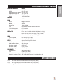
SPECIFICATIONS FOR SWEEP STAR 48H
WEIGHTS AND DIMENSIONS HIGH LIFT
Length 121" (307 cm)
Width 60" (153 cm)
Height with Hopper Down 63" (160 cm)
Height with Hopper Up 126" (320 cm)
Wheel Base 70" (179 cm)
Weight 1900 lb (862 kg)
SOUND LEVEL
At ear level 90 dB
ENGINE
Make Briggs & Stratton
Model# 356447
Type / Spec# 0263G1
Horsepower 18 Hp (13kW)
Fuel Unleaded 87 Octane Gasoline Minimum
Cooling System Air Cooled
Lubrication System Full Pressure
Alternator 16 Amp
WHEELS & TIRE Front: One 18 x 9.50 x 8 Multi-rib (20 psi (1.4 bar))
Rear: Two 22 x 11.00 - 10 4-ply (20 psi (1.4 bar))
Castor: 9 x 3.50 - 4 (20 psi (1.4 bar))
SPEED
Forward Speed 0 to 10 m.p.h. (0-16 kph)
Reverse Speed 0 to 4 m.p.h. (0-6 kph)
BATTERY Automotive IBS type 45-12 volt
BCI Group Size 45
Cold Cranking Amps 480 minimum
Ground Terminal Polarity Negative (-)
Maximum Length 9" (23 cm)
Maximum Width 5.38" (14 cm)
Maximum Height 9" (23 cm)
FLUID CAPACITY
Crankcase Oil See Engine Manual
Fuel 6 gallon (22,7 liters)
Hydraulic Fluid 5 gallon (19 liters)
Grade of Hydraulic Fluid SAE 10W-40 API Service SJ or higher Motor Oil
OPTIONAL EQUIPMENT
48-502 48" Brush Reel Kit (includes pillow blocks and pulley drive)
48-503 48" Finger Reel Kit (includes pillow blocks and pulley drive)
48-501 Hopper Dust Shield

Service
4
MAINTENANCE
Before servicing or making adjustments to the machine, stop engine, set park
break, block wheels and remove key from ignition.
Follow all procedures and ONLY use parts prescribed by the manufacturer.
Read the engine manual before maintenance.
LUBRICATION
Use No. 2 General Purpose Lithium Base Grease and lubricate every 100 hours. The Sweep Star 48H has
fteen grease ttings.
A. One on the top of each tower.
B. One on the center of park brake relay on rear axle.
C. One on each pedal under the oorboard.
D. One on the pillow block bearing on each end of nger/brush reel.
E. One on caster wheel mount bracket.
F. One on reel clutch relay. One on reel clutch belt tightener.
G. One on pedal pivot arm.
H. One on rod end of the tailgate cylinder.
I. Pump idler Arm.

Service
5
MAINTENANCE
HYDRAULIC OIL
1. Use SAE 10W-40 API Service SG motor oil.
2. For proper warranty, change oil every 500 hours or annually, which ever is rst and change the lter
after the rst 50 hours, then every 250 hours thereafter.
3. The oil level should be 2" to 2
1
/
2
" (5 - 6.4 cm) from top of ll neck when uid is cold. Do not overll.
4. After changing oil and/or lter, run the machine for a few minutes. Check oil level and for leaks.
5. Always use caution when lling hydraulic oil tank or checking level to keep system free of contaminants.
Check and service more frequently when operating in extremely cold, hot or dusty conditions.
6. If natural color of uid is now black or smells burnt, it is possible that an overheating problem exists.
7. If uid becomes milky, water contamination may be a problem.
8. If either of the above conditions happen, change oil and lter immediately after uid is cool and nd
cause. Take uid level readings when system is cold.
9. In extreme temperatures you can use straight weight oil. We recommend SAE 30W API Service SG
when hot (above 90°F (33°C)) and SAE 10W API Service SG when cold (below 32°F (0°C)) ambient
temperature. Use either motor oil or hydraulic oil, but do not mix.
10. Oil being added to the system must be the same as what is already in the tank. Mark tank ll area as to
which type you put in.
ENGINE OIL
Change and add oil according to chart below. Do not overll. Engine oil capacity is 2 quarts. We recommend
high-quality detergent oils classied for service SF, SG, SH, SJ or higher. Do not use special additives. Out-
door temperatures determine the proper oil viscosity for the engine. Use the chart to select the best viscosity
for the outdoor temperature range expected.
SAE Viscosity Grades
Use of multi-viscosity oils (10W-30, etc.) above 80° F (27° C) will result in high oil consumption and possible
engine damage. Check oil level more frequently if using these types of oils.
SAE 30 oil, if used below 40° F (4° C), will result in hard starting and possible engine bore damage due to
inadequate lubrication.

6
Service
MAINTENANCE
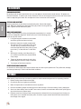
TIRE PRESSURE
Caution must be used when inating a low tire to recommended pressure. Over inating can cause tires to ex-
plode. Front and rear tires and caster wheel should be 20 psi (1.4bar) maximum. Improper ination will reduce
tire life considerably.
WHEEL MOUNTING PROCEDURE
REAR WHEELS
1. Set park brake. Turn machine o and remove key.
2. Block one of the other wheels.
3. Loosen nuts slightly on wheel to be removed.
4. Jack up machine being careful not to damage underside of machine.
5. Remove nuts, remove wheel.
5. Place new wheel on hub lining up bolt holes.
6. Torque nuts to 64-74 ft/lb (87-100Nm) using a cross pattern. Re-torque after rst 8 hours and every 250
hours thereafter.
7. Lower machine to ground and remove blocks and jack.
FRONT WHEEL
1. Set park brake. Turn machine o and remove key.
2. Block one of the other wheels.
3. Remove cotter pins from each end of the axle.
4. Remove axle nuts, machine bushings and axle locks.
5. Jack up front of machine being careful not to damage underside of machine.
6. Wheel and axle will come out of slots in the u-bracket, pull wheel forward.
7. Place new wheel on hub lining up bolt holes.
8. Torque nuts to 64-74 ft/lb (87-100Nm) using a cross pattern. Re-torque after rst 8 hours and every 250
hours thereafter.
9. Place wheel back on front fork. Tighten all bolts.
10. Lower machine to ground and remove blocks and jack.

Service
7
MAINTENANCE
BATTERY
Batteries normally produce explosive gases which can cause personal injury. Do not allow ames, sparks or
any ignited object to come near the battery. When charging or working near battery, always shield your eyes
and always provide proper ventilation.
Battery cable should be disconnected before using “Fast Charge”.
Charge battery at 15 amps for 10 minutes or 7 amps for 30 minutes. Do not exceed the recommended
charging rate. If electrolyte starts boiling over, decrease charging.
Always remove grounded (-) battery clamp rst and replace it last. Avoid hazards by:
1. Filling batteries in well-ventilated areas.
2. Wear eye protection and rubber gloves.
3. Avoid breathing fumes when electrolyte is added.
4. Avoid spilling or dripping electrolyte.
Battery Electrolyte is an acidic solution and should be handled with care. If
electrolyte is splashed on any part of your body, ush all contact areas imme-
diately with liberal amounts of water. Get medical attention immediately.
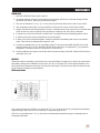
JUMP STARTING
Use of booster battery and jumper cables. Particular care should be used
when connecting a booster battery. Use proper polarity in order to prevent
sparks.
To jump start (negative grounded battery):
1. Shield eyes.
2. Connect ends of one cable to positive (+) terminals of
each battery, rst (A) then (B).
3. Connect one end of other cable to negative (-) terminal
of "good" battery (C).
4. Connect other end of cable (D) to engine block on unit
being started (NOT to negative (-) terminal of battery)
To prevent damage to other electrical components on unit being started, make certain that engine is at idle
speed before disconnecting jumper cables.
TOWING
When it is necessary to move the Sweep Star 48H without engine running, the bypass valve built into hydro-
static pump must be “open” by turning it
1
/
4
turn. An “open” valve allows uid to pass through the wheels free-
ly. When normal, driven, operation is desired, valve should be closed by turning it
1
/
4
turn. Failure to “close” the
valve with engine running means no power to wheels. Tow slowly. 2 m.p.h. or less.
The bypass valve is a
3
/
8
diameter shaft with two at spots on the sides so you can turn it. On the high lift it is
on the top of the hydrostatic.
FILTER PACK
Filters can be removed and cleaned by shaking or use a low pressure water hose. Filter will disintegrate if
cleaned under high pressure.

Service
8
SERVICE CHART
Before servicing or making adjustments to the machine, stop engine, set
park break, block wheels and remove key from ignition.
Follow all procedures and ONLY use parts prescribed by the manufacturer.
Read the engine manual before maintenance.
The suggested maintenance checklist is not oered as a replacement for the manufacturer’s engine manual
but as a supplement. You must adhere to the guidelines established by the manufacturer for warranty cover-
age. In adverse conditions such as dirt, mud or extreme temperatures, maintenance should be more frequent.
Maintenance Service Interval Maintenance Procedure
Aer the rst 8 operating hours Torque the wheel lug nuts. (64-74 /lb (87-100 Nm))
Change the engine oil lter.
Before each use daily Check the engine oil level.
Clean area around muer and controls.
Check the hydraulic uid level.
Check the tire pressure.
Check and clean Debris Filter Pack1
Check condition of hydraulic hoses and ttings.
Inspect and clean the machine.
Aer the rst 50 hours Change Hydraulic Oil Filter.
Every 100 hours Clean or change air lter.1
Clean pre-cleaner.1
Change engine oil and lter.
Replace spark plug .
Lubricate machine.
Clean or change remote air cleaner.
Check the battery uid level and cable connections..
Check muer and spark arrestor.
Check belt tension .
Every 250 hours Check engine valve clearance and adjust if necessary.
Check idle speed.
Clean battery terminals.
Change hydraulic oil lter.
Torque the wheel lug nuts. (64-74 /lb (87-100 Nm))
Every 500 hours or yearly Change fuel lter.
Change hydraulic oil and lter.
Clean oil cooler ns.1
Clean air cooling system.1
Check safety lter in remote air cleaner.
1 In dusty conditions or when airborne debris is present, clean more oen.

Service
9
MAINTENANCE CHART
Duplicate this page for routine use.
Maintenance Check Item For the week of:
Mon Tues. Wed. urs. Fri. Sat. Sun.
Check the Safety Seat Switch
Check Steering Operation
Check the fuel level
Check the engine oil level.
Clean the air lter
Clean the engine cooling ns.
Check for unusual engine noises
Check the hydraulic oil level
Check hydraulic hoses and ttings for
damage
Check for uid leaks.
Check the tire pressure
Check the Instrumentation
Inspect electrical system for frayed wires
Check park brake adjustment
Change oil lter.
Change oil.
Lubricate Machine
Ensure all warning decals are intact.
Areas of Concern
Inspection Performed by:
Item Date Information

Service
10
ADJUSTMENTS
PARK BRAKE ADJUSTMENT
By turning knob on end of park brake lever you can tighten or loosen brake a small amount. To tighten turn
the knob clockwise. To loosen turn counter clockwise. If this is not enough turn clevis on the rear of the brake
cable to adjust length of cable. Do not adjust the clevis on the front of the machine.
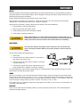
STEERING CHAIN ADJUSTMENT
Steering Sprockets (A) should be level with each other. Check with straight
edge. Make any adjustments. Slide Idler Pulley (B) so that it is snug onto the
chain. Tighten all nuts and bolts in place.
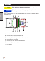
WHEEL 'CREEP' ADJUSTMENT
‘Creep’ is when engine is running and hydrostatic transmission is in neutral,
but due to inadequate alignment, wheels still move. Do the following proce-
dures to stop this motion.
1. Lift up and support machine so rear wheels
are o the ground and can turn freely.
2. Below the seat is the engine compartment.
The shift arm (D) is on the side of the pump.
The idler arm (F) is attached to the pump
mount bracket and has a idler pulley (C) that
runs in the "y" of the shift arm. Loosen bolt
(E).
3. With engine running, move idler pulley (C)
so it centers on the shift arm (D) and 'wheel
creep' stops.
4. Tighten all fasteners and test by using foot
pedal linkage to see that 'creep' is removed.
5. Turn engine o and lower machine.
RUBBER FINGERS AND NYLON BRUSHES
In normal use, rubber ngers and nylon brushes wear out and require replacement. They will break, dislodge,
and wear prematurely if used in less than ideal conditions.
STORAGE
When storing, remove the key from the key switch to avoid unauthorized persons from operating machine.
1. Before storing clean machine thoroughly.
2. Check bolts and nuts, tighten as necessary.
3. Make all repairs that are needed and remove any debris.
4. Remove the battery, adjust the electrolyte level and recharge it. Store the battery in a dry, dark place.
5. Store in a clean and dry area, but NOT near a stove, furnace or water heater which uses a pilot light or
any device that can create a spark.
6. Engines stored over 30 days need to be protected or drained of fuel to prevent gum from forming in a
fuel system or on essential carburetor parts. Check the engine manual and follow the instructions for
the storage of the engine.

Service
11
REEL HEIGHT ADJUSTMENT
Below are the various ways that the Sweep Star 48H caster wheels can be adjusted to accommodate for the
nger/brush reel height. By changing the two spacers around on the caster wheel fork you can experience a
range of ground clearances on the nger/brush reel. Keep both caster wheels at the same height.
These clearances change as the brush and nger reels wear.
1
/
2
" Spacer
Top Hole
Ground Clearance
Brush Reel
3
/
4
"
Finger Reel 1
1
/
8
"
1" Spacer
Top Hole
Ground Clearance
Brush Reel
5
/
8
"
Finger Reel 1
1
/
4
"
1" Spacer
1
/
2
" Spacer
Top Hole
Ground Clearance
Brush Reel 1
1
/
8
"
Finger Reel 1
7
/
16
"
1" Spacer(2 per)
1
/
2
" Spacer(1 per)
Bottom Hole
Ground Clearance
Brush Reel 1
1
/
2
"
Finger Reel 1
7
/
8
"

12
Diagrams
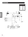
WIRING DIAGRAM
Color Code Chart
Bl Blue
Br Brown
Y Yellow
Grn Green
O Orange
R Red
B Black
P Purple

13
Diagrams
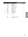
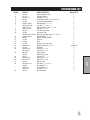
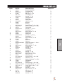
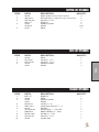
WIRING DIAGRAM PARTS LIST
REF# PART# DESCRIPTION QUANTITY
1 76-337 Electric Clutch 1
2 15-725 Mount Panel End 1
15-726 Lighted Switch, On-None-O 1
15-732 Rocker Switch, Green 1
3 12-804 Hour Meter 1
4 13-488 Key Switch with Hardware 1
5 50-359 Warning Indicator Light 1
6 17-271 Pigtail 1
7 8975 Circuit Breaker, 30 amp 1
8977 Circuit Breaker Boot 1
8 48-268 Black Battery Cable 1
9 22-073 Battery 1
48-166 Battery Hold-down 1
10 22-065 Black Starter Cable
11 13-750 Solenoid with Connector 1
12 48-157 Red Battery Cable 1
13 14-292 Seat Switch 1
48-511 Wire Harness 1
8874 Line Connector Blue (Voltage Regulator) 1
8875 Bullet Terminal (Ignition Module) 1
8963 Heat Shrink 2

14
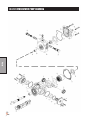
Diagrams
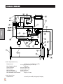
HYDRAULIC DIAGRAM
48-267 Hydrostatic Pump
Displacement Variable to 1.44 in
3
/R (23.6 cm
3
/R)
22.44 gpm (84.94 lpm) at 3600 rpm
Max Operating Speed 3600 rpm
Rated Pressure 3000 psi (206.8 bar)
Max Pressure 5000 psi (344.7 bar)
Max Inlet Vacuum 6 in Hg (.203 bar)
Max Inlet Temperature 225°F (107°C)
Max Allowable Case Pressure 25 psi (1.72 bar)
48-266 Gear Pump
Displacement .40 in
3
/R (6.6 cm
3
/R) 6.23 gpm (25.39 lpm)

15
Diagrams
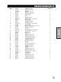
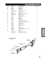
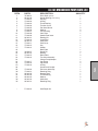
HYDRAULIC DIAGRAM PARTS LIST
REF# PART# DESCRIPTION QUANTITY
1 76-242 Hydraulic Cylinder 2
76-242-01 Seal Kit
2 48-012 Hydraulic Hose, 80" 1
3 48-013 Hydraulic Hose, 60" 1
4 76-238 Wheel Motor 2
5 34-057 Tee 2
6 48-244 Hydraulic Tube 4
7 8832-12.5 Suction Hose,
3
/
4
ID x 12.5" 1
18-040 Hose Clamp 2
8 48-257 Hydraulic Hose, 77" 2
9 48-267 Hydrostatic Pump 1
10 8832-42.5 Suction Hose,
3
/
4
ID x 42.5" 1
18-040 Hose Clamp 2
. 11 48-266 Gear Pump (replacement; no repair) 1
12 48-253 Hydraulic Hose, 56" 1
13 20-576 Oil Filter 1
20-576-01 Filter Element (replacement only) 1
14 8832-15 Suction Hose,
3
/
4
ID x 15" 1
18-040 Hose Clamp 2
16 60-473 Oil Tank 1
17 48-249 Hydraulic Hose, 65" 1
18 48-252 Hydraulic Hose, 150" 1
19 48-258 3-Bank Hydraulic Valve 1
20 48-255 Hydraulic Hose, 44" 1
21 48-256 Hydraulic Hose, 41" 1
22 76-478 Hydraulic Cylinder 1
14-531 Seal Kit
23 18-173 Tee
3
/
8
Junction Union 2
24 27-065 Hydraulic Hose, 26" 1
25 10-554 Hydraulic Cylinder 1
14-529 Seal Kit
26 48-248 Hydraulic Hose, 147" 1
27 48-014 Hydraulic Hose, 10.5" 1
28 8832-20 Suction Hose,
3
/
4
ID x 20" 1
18-040 Hose Clamp 2
29 45-382 Oil Cooler 1
30 48-251 Hydraulic Hose, 38" 1
31 48-250 Hydraulic Hose, 44" 1
32 48-247 Hydraulic Hose, 92" 1
33 48-254 Hydraulic Hose, 63" 1

16
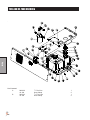
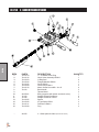
Diagrams
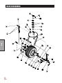
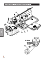
SMITHCO ENGINEERED ROLL OVER DRAWING

17
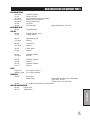
Reference
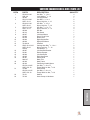
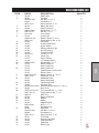
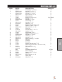
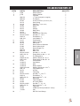
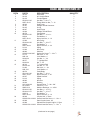
SMITHCO ENGINEERED ROLL OVER PARTS LIST
REF# PART# DESCRIPTION QUANTITY
1 HB-38-16-100 Hex Bolt,
3
/
8
- 16 x 1 4
HWL-38 Lock Washer,
3
/
8
- 16 4
2 48-295 Left Support Bar 1
3 HB-12-13-300 Hex Bolt,
1
/
2
-13 x 3 6
HNTL-12-13 Nylon Lock Nut,
1
/
2
-13 6
4 HB-38-16-100 Hex Bolt,
3
/
8
- 16 x 1 4
HNTL-38-16 Nylon Lock Nut,
3
/
8
-16 4
5 HB-12-13-125 Hex Bolt,
1
/
2
-13 x 1
1
/
4
4
HNTL-12-13 Nylon Lock Nut,
1
/
2
- 13 4
6 48-208 Roll Bar 1
7 48-313 Belt Guard 1
8 48-207 Left Hand Mount 1
25-286 Decal, Pinch Point 3
9 60-106 Brake Lever 1
10 48-294 Right Support Bar 1
11 48-206 Right Hand Mount 1
12 76-198-03 Seat Belt 1
13 HBCL-38-16-100 Carriage Hex Bolt,
3
/
8
- 16 x 1 2
HNTL-38-16 Nylon Lock Nut,
3
/
8
- 16 2
HW-38 Flat Washer,
3
/
8
2
14 48-287 Left Seat Belt Bracket 1
15 50-081 Rubber Bumper 2
16 48-284 Left Seat Brace 1
17 48-285 Right Seat Brace 1
18 48-307 Grass Chute 1
8803-47 Black Trim 1
19 48-300 Main Frame 1
20 48-324 Park Brake Handle Mount 1
HB-516-18-225 Hex Bolt,
5
/
16
-18 x 2
1
/
4
2
HNFL-516-18 Flange Whiz-loc Nut,
5
/
16
-18 2
21 13-099 Hose Clamp 1
HB-516-18-125 Hex Bolt,
5
/
16
-18 x 1
1
/
4
1
HNFL-516-18 Flange Whiz-loc Nut,
5
/
16
-18 1
22 76-151 Washer 4
23 76-336 Hose Clamp w/ Hardware 1

18
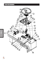
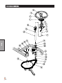
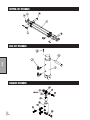
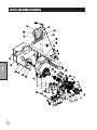
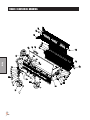
Parts
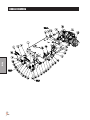
NOSE CONE DRAWING
Page is loading ...
Page is loading ...
Page is loading ...
Page is loading ...
Page is loading ...
Page is loading ...
Page is loading ...
Page is loading ...
Page is loading ...
Page is loading ...
Page is loading ...
Page is loading ...
Page is loading ...
Page is loading ...
Page is loading ...
Page is loading ...
Page is loading ...
Page is loading ...
Page is loading ...
Page is loading ...
Page is loading ...
Page is loading ...
Page is loading ...
Page is loading ...
Page is loading ...
Page is loading ...
Page is loading ...
Page is loading ...
Page is loading ...
Page is loading ...
Page is loading ...
Page is loading ...
Page is loading ...
Page is loading ...
Page is loading ...
-
 1
1
-
 2
2
-
 3
3
-
 4
4
-
 5
5
-
 6
6
-
 7
7
-
 8
8
-
 9
9
-
 10
10
-
 11
11
-
 12
12
-
 13
13
-
 14
14
-
 15
15
-
 16
16
-
 17
17
-
 18
18
-
 19
19
-
 20
20
-
 21
21
-
 22
22
-
 23
23
-
 24
24
-
 25
25
-
 26
26
-
 27
27
-
 28
28
-
 29
29
-
 30
30
-
 31
31
-
 32
32
-
 33
33
-
 34
34
-
 35
35
-
 36
36
-
 37
37
-
 38
38
-
 39
39
-
 40
40
-
 41
41
-
 42
42
-
 43
43
-
 44
44
-
 45
45
-
 46
46
-
 47
47
-
 48
48
-
 49
49
-
 50
50
-
 51
51
-
 52
52
-
 53
53
-
 54
54
-
 55
55


Smithco Sweep Star 48-500 Owner's manual
- Type
- Owner's manual
Ask a question and I''ll find the answer in the document
Finding information in a document is now easier with AI
Related papers
-
Smithco Sweep Star 48-500 Owner's manual
-
-
-
-
-
-
-
-
-
Other documents
-
Toro Brush Guard Kit, Twister Utility Vehicle Installation guide
-
 Mi-T-M Hose Reel Owner's manual
-
 Rugged Ridge 11503.90 Installation guide
-
 Nilfisk-Advance America RS 501 User manual
-
GEM SHORT BED WITH SIDES KIT Quick start guide
-
 Water Tech NE4384 User guide
-
 Farm-Tuff MS-1800 Owner's manual
-
Husqvarna 967055801 Installation guide
-
Logosol Bar Nose Steering Saw Units Assembly Instructions
-
Estate 600a Owner's manual


