Page is loading ...

PARTS & SERVICE
MANUAL
SWEEP STAR 60
GAS & DIESEL with Electric Clutch
Models 76-000-B and 77-100-B
Starting Serial #: D or G 1599 September, 2002
SMITHCO PRODUCT SUPPORT
1-800-891-9435
Hwy SS and Poplar Avenue, Cameron WI 54822
E-mail: [email protected]

Introduction Service Diagrams Parts Accessories Reference
CONTENTS
Introduction .........................................1-10
Introduction ................................................................................. 1-3
Safe Practices.............................................................................2
Specifications..............................................................................3
Optional Equipment ....................................................................3
Service ........................................................................................4-11
Maintenance ........................................................................... 4-6
Service Chart Kohler Command 25 hp........................................7
Service Chart Kubota Diesel 18.8 hp ..........................................8
End User’s Service Chart............................................................9
Adjustments ..............................................................................10
Storage .....................................................................................10
Notes ........................................................................................ 11
Diagrams...................................................................................12-17
Diesel Wiring Diagram .........................................................12-13
Gas Wiring Diagram ............................................................14-15
Hydraulic Diagram ...............................................................16-17
Parts ..........................................................................................18-61
Body and Frame ..................................................................18-19
Steering................................................................................20-21
Front Fork ............................................................................22-23
Linkage ................................................................................24-25
Gas Console ........................................................................26-27
Diesel Console.....................................................................28-29
Fuel Tank and Oil Tank ........................................................30-31
Oil Filter ...............................................................................32-33
Hydraulic Lift Cylinder ..........................................................32-33
Reel Lift Cylinder..................................................................34-35
Tailgate Cylinder ..................................................................34-35
Kohler Gas Engine and Exhaust ..........................................36-37
Kubota Diesel Engine and Exhaust ......................................38-41
Belt Drive .............................................................................42-43
Electric Clutch Driven Belt Drive ..........................................44-45
Finger Reel ..........................................................................46-47
Rear Axle .............................................................................48-49
Hopper .................................................................................50-51
Tailgate ................................................................................52-53
76-100 Eaton Hydrostatic Pump ..........................................54-55
76-197 Eaton Gear Pump ....................................................56-57
76-238 Rear Wheel Motor....................................................58-59
76-023 3-Bank Hydraulic Valve ............................................60-61
Accessories ..............................................................................62-65
76-198 Rollover Protection...................................................62-63
Installation Instructions..............................................................63
76-271 Dust/Dirt Filtration Pack ..........................................64-65
Reference ..................................................................................67-68
Decal List ..................................................................................67
Quick Reference Replacement Parts........................................68

1
Introduction
Information needed when ordering replacement parts:
1. Model Number of machine.
2. Serial Number of machine.
3. Name and Part Number of part.
4. Quantity of parts.
INTRODUCTION
Thank you for purchasing a product.
Read this manual and all other manuals pertaining to the Sweep Star 60 carefully as they have safety, operating,
assembly and maintenance instructions. Failure to do so could result in personal injury or equipment damage.
Keep manuals in a safe place after operator and maintenance personnel have read them. Right and left sides are
from the operator’s seat, facing forward.
All machines have a Serial Number and Model Number. Both numbers are needed when ordering
parts. The serial number plate on the Sweep Star 60 is located on the left front main frame, in front of the engine.
Refer to engine manual for placement of engine serial number.
For easy access record your Serial and Model numbers here.

2
Introduction
SAFE PRACTICES
1. It is your responsibility to read this manual and all publications associated with this machine (engine, accesso-
ries and attachments).
2. Never allow anyone to operate or service the machine or its attachments without proper training and instructions.
Never allow minors to operate any equipment.
3. Learn the proper use of the machine, the location and purpose of all the controls and gauges before you operate
the equipment. Working with unfamiliar equipment can lead to accidents.
4. Wear all the necessary protective clothing and personal safety devises to protect your head, eyes, ears, hands
and feet. Operate the machine only in daylight or in good artificial light.
5. Inspect the area where the equipment will be used. Beware of overhead obstructions and underground ob-
stacles. Stay alert for hidden hazards.
6. Never operate equipment that is not in perfect working order or without decals, guards, shields, or other protec-
tive devices in place.
7. Never disconnect or bypass any switch.
8. Carbon monoxide in the exhaust fumes can be fatal when inhaled, never operate a machine without proper
ventilation.
9. Fuel is highly flammable, handle with care.
10. Keep engine clean. Allow the engine to cool before storing and always remove the ignition key.
11. After engine has started, machine must not move. If movement is evident, the neutral mechanism is not ad-
justed correctly. Shut engine off and readjust so the machine does not move when in neutral position.
13. Never use your hands to search for oil leaks. Hydraulic fluid under pressure can penetrate the skin and cause
serious injury.
14. This machine demands your attention. To prevent loss of control or tipping of the vehicle:
A. Use extra caution in backing up the vehicle. Ensure area is clear.
B. Do not operate on a slope greater than 10°. Pay carefuk attention to the inclinometer on you machine.
C. Do not stop or start suddenly on sloped surfaces.
D. Reduce speed on slopes and in all turns. Use caution when changing directions on all surfaces.
E. Do not change directions of travel on any slope.
F. Do not operate debris hopper lift or tailgate while on slopes.
G. Stay alert for holes in the terrain and other hidden hazards.
15. Before leaving operator’s position for any reason:
A. Disengage all drives.
B. Lower all attachments to the ground.
C. Set park brake.
D. Shut engine off and remove the ignition key.
16. Keep hands, feet and clothing away from moving parts. Wait for all movement to stop before you clean, adjust or
service the machine.
17. Keep the area of operation clear of all bystanders.
18. Never carry passengers.
19. Stop engine before making repairs/adjustments or checking/adding oil to the crankcase.
20. Use parts and materials supplied by SMITHCO only. Do not modify any function or part.
21. Do not remove the radiator cap when the engine is hot. When cooled, loosen cap slightly to the stop to relieve
any pressure before removing the cap completely.
These machines are intended for operation by well trained persons performing professional maintenance on golf
courses, sports turf, and any other area maintained turf and related trails, paths and lots. No guaranty as to the
suitability for any task is expressed or implied.

3
Introduction
SPECIFICATIONS
FOR SWEEP STAR 60 GAS & DIESEL
WEIGHTS AND DIMENSIONS
Length 129" (328 cm)
Width 74.5" (179 cm)
Height with Hopper Down 66" (168 cm)
Height with Hopper Up 127" (323 cm)
Wheel Base 68.5" (174 cm)
Weight 2200 lbs (998 kg)
SOUND LEVEL GAS ENGINE DIESEL ENGINE
At ear level 92 dB 98 dB
At 3 ft (0.914 m) 86 dB 96 dB
At 30 ft (9.14 m) 64 dB 74 dB
ENGINE GAS DIESEL
Make Kohler Kubota
Model# Command CH25S D 722B-1
Type / Spec# PA-68525
Horsepower 25 Hp (18 kw) 18.8 Hp (14 kw)
Fuel Unleaded 87 Octane No. 2 Diesel
Gasoline Minimum
Cooling System Air Cooled Liquid Cooled
Lubrication System Full Pressure Full Pressure
Alternator 15 Amp 15 Amp
Tire & Wheels Front: One 18 x 9.50 x 8 Multi-rib (20 psi; 1.4 bar)
Front tire and wheel fluid filled to 50 lbs. total. 28 pints of windshield washer
fluid or equivalent.
Rear: Two 24 x 13.00 x 12 Super Soft (18 psi; 1.3 bar)
Castor: 9 x 3.5 - 4 (20 psi; 1.4 bar)
SPEED
Forward Speed 0 to 12 m.p.h. (0-19 kph)
Reverse Speed 0 to 4 m.p.h. (0-6 kph)
BATTERY Automotive type 45 -12 volt
BCI Group Size 45
Cold Cranking Amps 480 minimum
Ground Terminal Polarity Negative (-)
Maximum Length 9" (23 cm)
Maximum Width 5.38" (14 cm)
Maximum Height 9" (23 cm)
FLUID CAPACITY
Crankcase Oil See Engine Manual
Fuel 5 gallon (19 liters)
Hydraulic Fluid 5 gallon (19 liters)
Cooling Kubota approximately 1 gallon (3.8 liters)
Grade of Hydraulic Fluid SAE 10W-40 API Service SJ or higher Motor Oil
OPTIONAL EQUIPMENT
77-328 60" Brush Kit
76-329 60" Finger Reel Kit
76-271 Filtration Pack
76-198 Certified R.O.P.S. (for Sweep Star 60)
77-218 Triple Castor Wheel Kit

4
Service
MAINTENANCE
LUBRICATION
Use No. 2 General Purpose Lithium Base Grease and lubricate every 100 hours. The Sweep Star 60 has ten
grease fittings.
One on the outside of each tower.
One on the center of park brake relay on rear axle.
One on hydrostatic pedal under the floorboard.
One on the pillow block bearing on each end of finger reel.
One on castor wheel mount bracket.
One on hydrostatic forward and reverse relay.
One on reel clutch belt tightener.
One on rod end of the tailgate cylinder.
Every 500 hours of operation, separate the hydrostatic pump from the engine. Clean the splined areas and
lightly grease the male portion of the pump spline. Use either Dow Corning
®
G-N Metal Assembly Paste or
#77 Assembly Paste (Kohler # 25 357 12-s).
As you remount the pump to the engine, be certain the mating surface are clean and free of any foreign
material and that the pump is correctly aligned.
HYDRAULIC OIL
1. Use SAE 10W-40 API Service SJ or higher motor oil.
2. For proper warranty, change oil every 500 hours or annually, which ever is first and change the filter after
the first 20 hours, then at 100 hours, then every 250 hours thereafter.
3. The oil level should be 2" to 2
1
/2" from top of the tank when fluid is cold. Do not overfill.
4. After changing oil and/or filter, run the machine for a few minutes. Check oil level and for leaks.
5. Always use caution when filling hydraulic oil tank or checking level to keep system free of contaminants.
Check and service more frequently when operating in extremely cold, hot or dusty conditions.
6. If natural color of fluid is now black or smells burnt, it is possible that an overheating problem exists.
7. If fluid becomes milky, water contamination may be a problem.
8. If either of the above conditions happen, change oil and filter immediately after fluid is cool and find cause.
Take fluid level readings when system is cold.
9. In extreme temperatures you can use straight weight oil. We recommend SAE 30W API Service SJ or
higher when hot (above 90°F (33°C)) and SAE 10W API Service SJ or higher when cold (below 32°F (0°C))
ambient temperature. Use either motor oil or hydraulic oil, but do not mix.
10. Oil being added to the system must be the same as what is already in the tank. Mark tank fill area as to
which type you put in.

5
Service
MAINTENANCE
(CONTINUED)
TIRE PRESSURE
Caution must be used when inflating a low tire to recommended pressure. Over inflating can cause tires to ex-
plode. Front tires and castor wheel should be 20 psi (1.4 bar), rear tires should be 18 psi (1.3 bar) maximum.
Improper inflation will reduce tire life considerably.
ENGINE OIL FOR KOHLER
Change and add oil according to charts below. Do not overfill. Use a high quality detergent oil. For Kohler engine
use oil classified “For Service SJ or higher” SAE 30 oil. For Kubota Diesel engine use oil classified “For Service
CC, CD or CE” API oil. Use no special additives with recommended oils. Do not mix oil with gasoline.
SAE 30 oil, if used below 40° F (4° C), will result in hard starting and possible engine bore damage due to inad-
equate lubrication.
SAE Viscosity Grades
Starting Temperature Range Anticipated Before Next Oil Change
TOWING
When it is necessary to move the Sweep Star 60 without engine running, the bypass valve built into hydrostatic
pump must be “open” by turning it counterclockwise. The valve is located on bottom left of pump. An “open” valve
allows fluid to pass through the wheels freely. When normal, driven, operation is desired, valve should be closed
by turning it clockwise. Failure to “close” the valve with engine running means no power to wheels.
BATTERY
Batteries normally produce explosive gases which can cause personal injury. Do not allow flames, sparks or any
ignited object to come near the battery. When charging or working near battery, always shield your eyes and
always provide proper ventilation.
Battery cable should be disconnected before using “Fast Charge”.
Charge battery at 15 amps for 10 minutes or 7 amps for 30 minutes. Do not exceed the recommended charging
rate. If electrolyte starts boiling over, decrease charging.
Always remove grounded (-) battery clamp first and replace it last. Avoid hazards by:
1. Filling batteries in well-ventilated areas.
2. Wear eye protection and rubber gloves.
3. Avoid breathing fumes when electrolyte is added.
4. Avoid spilling or dripping electrolyte.
Battery Electrolyte is an acidic solution and should be handled with care. If electrolyte is
splashed on any part of your body, flush all contact areas immediately with liberal amounts
of water. Get medical attention immediately.
FILTER PACK
Filter pack may be cleaned by shaking or spraying off with low pressure water. Filter will disintegrate if high
pressure is used on it.
Kohler Gas Engine Kubota Diesel Engine

6
Service
MAINTENANCE
(CONTINUED)
WHEEL MOUNTING PROCEDURE
REAR WHEELS
1. Set park brake. Turn machine off and remove key.
2. Block one of the other wheels.
3. Loosen nuts slightly on wheel to be removed.
4. Jack up machine being careful not to damage underside of machine.
5. Remove nuts, remove wheel.
5. Place new wheel on hub lining up bolt holes.
6. Torque nuts to 64-74 ft/lb (87-100 Nm) using a cross pattern. Torque again after first 10 hours and every
200 hours thereafter.
7. Lower machine to ground and remove blocks and jack.
FRONT WHEEL
1. Set park brake. Turn machine off and remove key.
2. Block one of the other wheels.
3. Remove cotter pins from each end of the axle.
4. Remove axle nuts, machine bushings and axle locks.
5. Jack up front of machine being careful not to damage underside of machine.
6. Wheel and axle will come out of slots in the u-bracket, pull wheel forward.
7. Place new wheel on hub lining up bolt holes.
8. Torque nuts to 64-74 ft/lb (87-100 Nm) using a cross pattern. Torque again after first 10 hours and every
200 hours thereafter.
9. Lower machine to ground and remove blocks and jack.
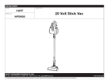
JUMP STARTING
Use of booster battery and jumper cables. Particular care should be used when connecting a
booster battery. Use proper polarity in order to prevent sparks.
To jump start (negative grounded battery):
1. Shield eyes.
2. Connect ends of one cable to positive (+) termi-
nals of each battery, first (A) then (B).
3. Connect one end of other cable to negative (-)
terminal of "good" battery (C).
4. Connect other end of cable (D) to engine block on
unit being started (NOT to negative (-) terminal of
battery)
To prevent damage to other electrical components on
unit being started, make certain that engine is at idle
speed before disconnecting jumper cables.
SWEEPING
While sweeping close tailgate frequently to ensure tailgate does not creep open.

7
Service
SERVICE CHART KOHLER COMMAND 25 HP
Before servicing or making adjustments to the machine, stop engine, set park break, block
wheels and remove key from ignition.
Follow all procedures and ONLY use parts prescribed by the manufacturer. Read the engine
manual before maintenance.
C=Check or Clean at specified intervals
R=Replace at specified intervals
* Tire pressure: 20 psi (1.4 bar) Front and Castor. 18 psi (1.3 bar) Rear.
† Replace hydraulic filter after the first 20, 100, and every 250 there after.
§ Torque tire nuts after the first 10 hours and every 200 hours there after (64 to 74 ft/lb (87-100 Nm))
¤ Change Oil and Filter after first 5 hours.
‡ Clean more often under dusty conditions or when airborne debris is present , replace air cleaner parts, if very dirty.
The suggested maintenance checklist is not offered as a replacement for the manufacturer’s engine manual but
as a supplement. You must adhere to the guidelines established by the manufacturer for warranty coverage. In
adverse conditions such as dirt, mud or extreme temperatures, maintenance should be more frequent.
Daily
As Required
100 Hours
200 Hours
250 Hours
300 Hours
400 Hours
Every 500 Hours/Yearly
¤ Engine Oil w/ Filter 2.1qt. (2 l) C R R R R R
¤ Engine Oil Filter R R R
Engine for Leaks and Loose Parts C C C C C C
‡ Air Cleaner (Paper Element) C C C C C R
‡ Pre-Cleaner (Every 25 hours) CCCCCCR
Spark Plugs R C C R
Idle Speed (1200 RPM) C C
‡ Cooling System C C C C C C
Belts and Hoses C C C
* Tire Pressure C C C C C C
Visual Inspection of Tires C C C C C C
Fuel Level C C
Fuel Filter R R
Hydraulic Oil C CC CCR
†Hydraulic Oil Filter R R
Hydraulic System for Leaks and Loose Parts C C C C C C
Battery Electrolyte Level C C C C C
Clean Battery Terminals C C
§ Torque Lug Nuts C C C
Lubricate C C C C C
Lubricate Splines on Hydrostatic Pump Every 500 hours

8
Service
SERVICE CHART KUBOTA DIESEL 18.8 HP
Before servicing or making adjustments to the machine, stop engine, set park break, block
wheels and remove key from ignition.
Follow all procedures and ONLY use parts prescribed by the manufacturer. Read the engine
manual before maintenance.
C=Check or Clean at specified intervals
R=Replace at specified intervals
* Tire pressure: 20 psi (1.4 bar) Front and Castor. 18 psi (1.3 bar) Rear.
† Replace hydraulic filter after the first 20, 100, and every 250 there after.
§ Torque tire nuts after the first 10 hours and every 200 hours there after (64 to 74 ft/lb (87-100 Nm))
¤ Change Oil and Filter after first 50 hours.
‡ Clean more often under dusty conditions or when airborne debris is present , replace air cleaner parts, if very dirty.
The suggested maintenance checklist is not offered as a replacement for the manufacturer’s engine manual but
as a supplement. You must adhere to the guidelines established by the manufacturer for warranty coverage. In
adverse conditions such as dirt, mud or extreme temperatures, maintenance should be more frequent.
Daily
As Required
100 Hours
200 Hours
250 Hours
300 Hours
400 Hours
Every 500 Hours/Yearly
¤ Engine Oil w/ Filter 4qt. (3.8 l) C R R R R R
¤ Engine Oil Filter R R R
Engine for Leaks and Loose Parts C C C C C C
‡ Air Cleaner (Paper Element) C C C C C C R
Idle Speed (1200 RPM) C C
‡ Cooling System C C C C C C
Belts and Hoses C C C
* Tire Pressure CCCCCC
Visual Inspection of Tires C C C C C C
Fuel Level C C
Fuel Filter R C C C C R
Hydraulic Oil C C C C C R
†Hydraulic Oil Filter R R
Hydraulic System for Leaks and Loose Parts C C C C C C
Battery Electrolyte Level C C C C C
Clean Battery Terminals C C
§ Torque Lug Nuts C C C
Lubricate C C C C C

9
Service
END USER’S SERVICE CHART
Daily
As Required
100 Hours
200 Hours
250 Hours
300 Hours
400 Hours
Every 500 Hours/Yearly
Engine Oil w/ Filter
Engine Oil Filter
Engine for Leaks and Loose Parts
Air Cleaner (Paper Element)
Pre-Cleaner (Every 25 hours)
Spark Plugs
Idle Speed
Cooling System
Belts and Hoses
Tire Pressure
Visual Inspection of Tires
Fuel Level
Fuel Filter
Hydraulic Oil
Hydraulic Oil Filter
Hydraulic System for Leaks and Loose Parts
Battery Electrolyte Level
Clean Battery Terminals
Torque Lug Nuts
Lubricate
Lubricate Splines on Gas Hydrostatic Pump Every 500 Hours

10
Service
ADJUSTMENTS
PARK BRAKE ADJUSTMENT
By turning knob on end of park brake lever you can tighten or loosen brake a
small amount. To tighten turn the knob clockwise. To loosen turn counter clock-
wise. If this is not enough turn clevis on brake cable to adjust length of cable.
STEERING CHAIN ADJUSTMENT
Steering Sprockets (A) should be level with each other. Check with straight edge.
Make any adjustments. Slide Idler Pulley (B) so that it is snug onto the chain.
Tighten all nuts and bolts in place.
WHEEL 'CREEP' ADJUSTMENT
‘Creep’ is when engine is running and hydrostatic transmission is in neutral, but
due to inadequate alignment, wheels still move. Do the following procedures to
stop this motion.
1. Lift up and support the unit so rear wheels are off the ground and can turn
freely.
2. On the side of hydrostatic transmission is the Shift Arm (C) . In the ‘V’
shaped notch of shift arm rests and Idler Pulley (D). This Pulley is mounted
on an Idler Arm (E).
3. Loosen bolt and nut holding Pulley to Idler Arm. Leave finger tight.
4. With engine running, slide the Pulley in Idler Arm slot until it centers on Shift
Arm on hydrostatic and wheel ‘creep’ stops.
5. Tighten all fasteners and test by using foot pedal linkage to see that the
‘creep’ is removed.
6. Turn the engine off and lower the machine.

11
Service
STORAGE
When storing, remove the key from the key switch to avoid unauthorized persons from operating machine.
1. Before storing clean machine thoroughly.
2. Check bolts and nuts, tighten as necessary.
3. Make all repairs that are needed and remove any debris.
4. Remove the battery, adjust the electrolyte level and recharge it. Store the battery in a dry, dark place.
5. Store in a clean and dry area, but NOT near a stove, furnace or water heater which uses a pilot light or any
device that can create a spark.
6. Engines stored over 30 days need to be protected or drained of fuel to prevent gum from forming in a fuel
system or on essential carburetor parts. Check the engine manual and follow the instructions for the
storage of the engine.

12
Diagrams
DIESEL WIRING DIAGRAM
Color Code Chart
Bl Blue
Br Brown
Y Yellow
Grn Green
O Orange
R Red
B Black
P Purple
W White

13
Diagrams
DIESEL WIRING PARTS LIST
REF# PART# DESCRIPTION QUANTITY
1 22-073 Battery 1
2 22-054 Black Battery Cable 1
3 75-518 Red Battery Cable 1
8892-40 Hose Wrap
1
/
4
x 40 1
4 50-359 Warning Indicator Lights 3
5 77-209 Hour Meter to Ground Wire 1
6 12-017 Hour Meter 1
7 34-146 Panel Mount Circuit Breaker 1
34-145 Circuit Breaker Boot 1
8 17-068 Key Switch 1
17-079 Key Set 1
9 77-223 Glow Lamp Timer 1
10 77-211 Glow Plug Indicator 1
11* 77-208-05 Air Pack Switch (part of engine) 1
12 77-207 Buzzer 1
13 77-201 Electric Fan 1
14* 77-233 Bosch Power Relay 1
15 77-226 Wire 17 to 19 Ignition Switch 1
16 77-208-01 Temperature Sender
(part of engine) 1
17 Oil Sender (part of engine) 1
18 8975 30Amp Circuit Breaker 1
8977 Circuit Breaker Boot 1
19 48-144 Circuit Breaker Wire 1
20* 77-203 Thermostat Wire Harness 1
77-205 Wire Harness (contains all wires except # 4 & 15 ) 1
* 77-235 Thermostat Kit

14
Diagrams
Color Code Chart
Bl Blue
Br Brown
Y Yellow
Grn Green
O Orange
R Red
B Black
P Purple
W White
GAS WIRING DIAGRAM

15
Diagrams
GAS WIRING PARTS LIST
REF# PART# DESCRIPTION QUANTITY
1 22-003 Ammeter 1
2 76-269 Power Wire to Hour Meter 1
3 12-017 Hour Meter 1
4 76-259 Ground Wire for Hour Meter 1
5 76-260 Ground Wire for Ignition Switch 1
6 34-146 Panel Mount Circuit Breaker 1
34-145 Circuit Breaker Boot 1
7 13-288 Key Switch with Hardware (Kohler #25 099 04) 1
76-310 Key Switch 1
8 50-359 Warning Indicator Light 1
9 Oil Sender (Part of Engine)
10 Ignition Module (Part of Engine)
11 Fuel Shut-Off Solenoid (Part of Engine)
12 Rectifier ( Part of Engine)
13 Starter (Part of Engine)
14 22-073 Battery 1
48-166 Battery Holddown 1
15 22-054 Black Battery Cable 1
16 75-518 Red Battery Cable 1
8892-40 Hose Wrap
1
/
4
x 40 1
17 Wire With Fuse (Part of Engine)
Fuse AGC 30
18 76-337 Electric Clutch 1
19 15-314 Toggle Switch 1
15-472 Switch Boot 1
20 76-342 Wire Switch to Ammeter 1
* 76-258 Wire Harness (Includes all wire color with *) 1

16
Diagrams
HYDRAULIC DIAGRAM
76-023 Hydraulic Valve
Relief Valve set at 2000 psi (137.93 bar)
76-100 Hydrostatic Pump
Displacement Variable to 1.44 in
3
/R (23.6 cm
3
/R)
22.44 gpm (84.94 lpm) at 3600 rpm
Max Operating Speed 3600 rpm
Rated Pressure 3000 psi (206.8 bar)
Max Pressure 5000 psi (344.7 bar)
Max Inlet Vacuum 6 in Hg (.203 bar)
Max Inlet Temperature 225°F (107°C)
Max Allowable Case Pressure 25 psi (1.72 bar)
76-197 Gear Pump
Displacement .40 in
3
/R (6.6 cm
3
/R) 6.23 gpm (25.39 lpm)

17
Diagrams
HYDRAULIC DIAGRAM PARTS LIST
REF# PART# DESCRIPTION QUANTITY
1 76-242 Hydraulic Cylinder 2
2 76-115 Hydraulic Hose 1
3 76-114 Hydraulic Hose 1
4 76-238 Wheel Motor 2
5 34-057 Tee 2
6 76-208 Hydraulic Hose 4
7 8832-21 Suction Hose 1
18-040 Hose Clamp 2
8 76-209 Hydraulic Hose 2
8895-50 1" Hose Wrap
(Top of Axle) 1
8895-48 1" Hose Wrap
(Bottom of Axle) 1
18-222 Hose Clamp 4
9 76-100 Hydrostatic Pump 1
10 76-207 Hydraulic Hose 1
8895-21 1" Hose Wrap 1
18-222 Hose Clamp 2
11 76-197 Gear Pump 1
12 76-104 Hydraulic Hose 1
8895-29 1" Hose Wrap 1
18-222 Hose Clamp 2
13 23-006 Oil Filter 1
23-031 Filter Element (Replacement Only) 1
14 76-105 Hydraulic Hose 1
8895-19 1" Hose Wrap 1
18-222 Hose Clamp 2
15 8917-38 Suction Hose
5
/
8
ID 1
18-040 Hose Clamp 2
16 48-135 Oil Tank 1
17 76-202 Hydraulic Hose 2
8892-24
1
/
4
" Hose Wrap 2
18 76-204 Hydraulic Hose 1
8892-26
1
/
4
" Hose Wrap 1
19 76-023 Hydraulic Valve 1
20 76-205 Hydraulic Hose 1
8892-31
1
/
4
" Hose Wrap 1
21 76-206 Hydraulic Hose 1
8895-27 1" Hose Wrap 1.
18-222 Hose Clamp 2
22 75-634 Hydraulic Cylinder 1
23 18-173 Tee
3
/8 Junction Union 2
24 76-117 Hydraulic Hose 1
25 50-456 Hydraulic Cylinder 1
26 76-203 Hydraulic Hose 1
8892-26
1
/
4
" Hose Wrap 1
27 76-116 Hydraulic Hose 1
28 8832-17 Suction Hose 1
18-040 Hose Clamp 2
8895-22 1" Hose Wrap (Gas Unit Only) 1
8895-20 1" Hose Clamp (Diesel Unit Only) 1
18-222 Hose Clamp 2

18
Parts
BODY AND FRAME DRAWING
When Filtration System is to be installed, Ref. 9 Hopper Screen Cover is to be removed.
When Filters are used, 76-262 Tailgate Screen is replaced by 76-249 Tailgate Filter Screen. 76-261 Hopper
Screen is replaced by 76-248 Hopper Filter Screen.
/