Page is loading ...

DA.24SL
®
CENTRALINA A MICROPROCESSORE
CONTROL UNIT WITH MICROCONTROLLER
MIKROCONTROLLER-STEUERUNG
CENTRALE A MICROCONTRÔLEUR
CENTRALITA A MICROPROCESADOR
AUTOMATISMI PER CANCELLI
®
L8542612
Rev. 01/99/00
Libro istruzioni
Operating instructions
Betriebsanleitung
Livret d’instructions
Libro de instrucciones
UNIONE NAZIONALE COSTRUTTORI
AUTOMATISMI PER CANCELLI, PORTE,
SERRANDE ED AFFINI
A
Z
I
E
N
D
A
C
E
R
T
I
F
I
C
A
T
A
UNI
EN ISO
9001

2
Dichiarazione CE di conformità Déclaration CE de conformité
EC declaration of confirmity Declaracion CE de conformidad
EG-Konformitatserklarung
Con la presente dichiariamo che il nostro prodotto
We hereby declare that our product
Hiermit erklaren wir, dass unser Produkt
Nous déclarons par la présente que notre produit
Por la presente declaramos que nuestro producto
DA.24SL
è conforme alle seguenti disposizioni pertinenti:
complies with the following relevant provisions:
folgenden einschlagigen Bestimmungen entspricht:
correspond aux dispositions pertinentes suivantes:
satisface las disposiciones pertinentes siguientes:
Direttiva sulla compatibilità elettromagnetica (89/336/
CCE, 93/68/CEE)
EMC guidelines (89/336/EEC, 93/68/EEC)
EMV-Richtlinie (89/336/EWG, 93/68/EWG)
Directive EMV (89/336/CCE, 93/68/CEE) (Compatibilité
électromagnétique)
Reglamento de compatibilidad electromagnética (89/336/
MCE, 93/68/MCE)
Norme armonizzate applicate in particolare:
Applied harmonized standards, in particular:
Angewendete harmonisierte Normen, insbesondere:
Normes harmonisée utilisées, notamment:
Normas armonizadas utilzadas particularmente:
EN 55022, EN 61000-3-2, EN 61000-3-3, EN 50082-1
Norme e specifiche tecniche nazionali applicate in
particolare:
Applied national technical standards and specifications, in
particular:
Angewendete nationale Normen und technische
Spezifikationen, insbesondere:
Normes et specifications techniques nationales qui ont été
utilisées, notamment:
Normas y especificaciones técnicas nacionales que se
utilizaron particularmente:
UNI 8612
Data/Firma
Direttiva sulla bassa tensione (73/23/CEE, 93/68/CEE)
Low voltage guidelines (73/23/EEC, 93/68/EEC)
Tiefe Spannung Richtlinie (73/23/EWG, 93/68/EWG)
Directive bas voltage (73/23/CEE, 93/68/CEE)
Reglamento de bajo Voltaje (73/23/MCE, 93/68/MCE)
Norme armonizzate applicate in particolare:
Applied harmonized standards, in particular:
Angewendete harmonisierte Normen, insbesondere:
Normes harmonisée utilisées, notamment:
Normas armonizadas utilzadas particularmente:
EN 60204-1, EN 60335-1
Data/Firma
AUTOMATISMI PER CANCELLI
®
Automatismi Benincà Srl
Via Capitello, 45
36066 SANDRIGO (VI)
ITALIA

10
Switchboard DA.24SL
Switchboard for a direct current motor 24Vdc, 200W
Characteristics:
The switchboard is adapted to the command of a 24Vdc, 200W motor for the motion of road barrier. Its
features are the following:
• Possibility to command by means of three separated push-buttons (Aperture, Stop and Closing
push-buttons) which cause respectively the aperture, the stop and the closing of the barrier.
• Possibility to command by means of one push-button (Step-by-step) with function Opens-Stop-
Closes-Stop or by means of a radio-control, by inserting a receiver in the preset connector.
• Presetting for the link of photo-devices which, in case of obscuration of the infrared ray, cause the
inversion of the movement of the barrier during the closing phase.
• Output for the connection of a blinker and a of a pilot for signalling open barrier.
• The function of automatic closing can be inserted and the pause length can be regulated.
• The speed of the braking device can be regulated.
• The sensitivity of the device for the detection of obstacles with amperometric sensor can be regu-
lated.
• In case of mains lacking, the working is through floating batteries and with battery charger board.
Structure:
The glass-fiber basis consists of the power part, of all the connections for the clutch boards and the
clamps for the power supplies and links.
Dimensions:
190x145x80mm (central unit board)
Power supply:
• 230Vca ±10%, 1.5A
• 20÷27Vcc, 25A max. provided by n° 2 hermetical lead batteries 12Vcc, 6.5Ah connected into series.
Protections:
Fuse protection against the short-circuit of the general supply line;
Fuse protection against the short-circuit of the auxiliary lines;
Fuse protection against the high tension line;
Varistor protection against the over-voltage, on high and low tension;
Electronic limiters protection against the short-circuit of the motor and the exceeding discharge of
batteries.
Attention!
The protection against the polarity inversion of the battery is subordinated to the use of corrected
value fuses and, in any case, it generates immediate voltages which are dangerous for both the
circuit and the operator! The maximum attention is requested to avoid the exchange of polarities!
Options:
• The clutch radio control card is superreactive or quartz, mono or bi-channel with available 2nd
channel output on the basis, on request.
• Output for electro-lock with selectable tension (12/24Vcc).
• Output for 2nd blinker.
• Battery charger board.
Attention!
The central unit without battery charger board does not work by inserting floating batteries.

11
1 2
A B
2° radio
channel
(on request)
Fuse 6.3A Fast
Central unit board
Fuse 1.6A Fast
Electro-lock
tension selection
Option
Open: 12Vcc
Closed: 24Vcc
Fuse 12A Delayed
Power
pilot
Battery
charger
board
R
A
D
I
O
B
O
A
R
D
L
O
G
I
C
B
O
A
R
D
Antemn
Aperture command (4)
Closing command (5)
Aperture brake (6)
Step-by-step command (10)
Accessories output
24Vcc
SSA
C
O
M.
Motor
Battery
To the primary
transformer
From the secondary
transformer
230Vac
Blink.1
Blink.2
(on request)
Electro-lock
(on request)
+
+
- - +
- +
Stop command (9)
Photo-device contact (8)
Closing brake (7)
1 2 3 4 5 6 7 8 9 10 11 12 13 C D E 14 15 1 2 3 4 1 2 3 4
Battery charge
board (on request)
Discharged
battery pilot
Fuse 25A Fast
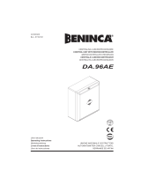
Links
• Do the links following the diagram, paying a special attention to the connections where the polarity
should be observed.
• Connect the clamps n°4 and n°10 to obtain the condominium function.
• The clamps A, B, C, D, E can be installed on request.
• See the ”Installation” paragraph for the cabling and the perfect installationof the system.
Attention!
The central unit without battery charger board cannot work with the floating batteries.

12
Settings and selections
Trimmer A (couple reg.): it adjusts the intervention time of the electronic power limiter. By turning it
counterclockwise the circuit is more sensitive (a light effort is enough to stop the movement); on the
contrary, by turning it clockwise the circuit becomes less sensitive and a great effort is necessary to
stop the motor; in this condition the motor can absorb up to 24A of peak (576W) at maximum speed.
Trimmer B (Cycle sp.): it adjusts the movement speed of the automation during the working cycle. By
turning it counterclockwise the speed decreases.
Trimmer C (Brake Sp.): it has the same function of the trimmer B as far as the brake cycle is concerned.
Trimmer D (Pause time): it adjusts the length of the pause between the aperture and the closing when
the function of automatic closing is inserted. By turning counterclockwise the time decreases (min. 2 s);
by turning it clockwise the time increases (max. 100 s).
Dip fix (Aut. Clos.): Open, it activates the function of automatic closing.
On the basis:
Condominium function: it is obtained by linking the clamps 4 (aperture push-button) and 10 (step-by-
step) together; in this way it is not possible to stop the aperture and invert the movement by means of
the step-by-step or radio-control.
- + - + - + - +
Connector
Trimmer A Trimmer B Trimmer C Trimmer D
Trimmer A Trimmer B Trimmer C Trimmer D
Automatic closing
Couple regulation
Cycle speed
regulation
Braking speed
regulation
Pause time
regulation
Dip-fix
Open
Closed
Central unit board

13
Installation
A B 1 2 3 4 5 6 7 8 9 10 11 12 13 C D E 14 15
OPTION
OPTION
OPTION
OPTION
OPTION
Antemn
C
O
M
M
O
N
P
U
S
H
B
U
T
T
O
N
A
P
E
R
T
U
R
E
C
L
O
S
I
N
G
B
R
A
K
E
A
P.
B
R
A
K
E
C
L.
P
H
O
T
O
D
E
V.
S
T
O
P
S
T
E
P
B
Y
S
T
E
P
S
S
A
C
O
M
M
O
N
O
U
T
P
U
T
S
(+)
B
L
I
N
K
E
R
Blinker
Open barrier pilot
Output 24Vcc
(Accessories)
+ -
1 2 3 4 5 6 7 8 9 10 11 12 13 14 15
C
O
M
M
O
N
Brake Cl.
Brake Ap.
Photodev.
Example:
Link to be made if closing
brake, aperture brake and
photo-devices are not used.
To the clamp n° 3
(common)
To the clamp n° 8
(photo-devices)
1° Photo-device 2° Photo-device

14
Keep the power cables away from the control cables. To avoid interference use two separate sheaths
(see EN 60204-1 15.1.3).
1) Connect the push-buttons and the devices following the diagrams.
2) All the inputs N.C. (normally closed) must be linked to the clamp n°3 (common) in case they are not
used.
3) All the inputs N.O. (normally open) must not be linked if they are not used.
4) If several couples of photo-devices are installed, contacts must be put into series.
5) The clamps A and B (2nd radio channel), C (2nd blinker) and D, E (electro-lock) can be installed on
request.
For the connections to these clamps see the diagram ”Links”.
6) Important!
In order to obtain a correct working of the accessories linked to the central unit (especially photo-
devices) it is very important that the whole system (motor + central unit) has only one ground refer-
ence.
It is then necessary to connect the motor frame with the clamp ”-” (negative) of the battery by
means of a cable on the central unit (see figure).
If a good ground is available it is better to connect the whole system with it.
-
+
+
+ -
-
M
Motor
Motor
frame
Motor
2 batteries 12Vcc
Batteries
230Vac
Linking cable
Linking cable
To the negative of battery
Example of a connection
Motor in d.c.
Fixing screws
motor frame
Central unit
24Vcc
Battery
- +
Central unit board
7) Place all the trimmers of the central unit board at mid-course and exclude the automating closing
for the while by closing the correspondent dip-fix on the board; if the electro-lock has been in-
stalled too, select the right power tension on the basis.
8) Place the automation at mid-course manually and check that the springs tension balance the weight
of the barrier perfectly.
9) Connect the line 230Vac and the eventual two hermetical leaden batteries 12Vcc, 3Ah, connected
into series, to the correspondent clamps, paying attention to the polarity: in the case the batteries
are linked, you should also insert the battery charger board in order to make them work.
10) Now the leds ”F.Apert.”, ”F.Clos.”, ”Photo” and ”Stop” should light on the basis and the leds
”P.Apert.”, ”P.Closing” and ”S.Bys” must remain obscured.
If this does not happen, check that the correspondent links are correct.
11) By moving the barrier manually, check that the led ”F.Apert.” turns off a little before the complete
aperture and that the led ”F.Clos.” turns off a little before the complete closing because of the
intervention respectively of the aperture brake and the closing brake.
12) Place the barrier at mid-course again and disconnect the device of manual triggering.

15
13) Push the button Aperture. The automation must move towards aperture; if it moves towards closing
push the stop button, disconnect the 230Vac and the batteries and invert the motor connections.
Connect the 230Vac and the batteries again and push the aperture push-button.
14) Do the adjustment of the working speed by means of the trimmer B (cycle speed) and wait for the
arrivel to the stop.
Regulate the intervention of the braking circuit, by placing the cams on the stops and by regulating
the trimmer C (braking speed) to obtain an easy stop.
15) Push the button Closing and adjust the power through the trimmer A (reg. couple) so that, with a
light effort, the movement can be stopped.
Remember that the setting of the couple adjustment trimmer depends on the adjustment done on
the cycle speed trimmer and on the brake speed trimmer; then, after any change of the cycle or
brake speeds the couple adjustement trimmer should be adjusted.
See the diagram ”Adjustments and selections”.
16) Check the working of the security devices, remembering that:
• by pushing the stop in any condition, the unit stops and waits for an order;
• the intervention of the photo-devices in closing phase causes the inversion of the movement at
once, while in aperture there is no intervention.
17) If you want to exclude the intervention of the step-by-step in aperture and in pause after automatic
closing (condominium function) connect the clamps n°4 (push-button of aperture) and n°10 (step-
by-step) together.
N.B.: Any time the manoeuvres cause confusion, disconnect the batteries and the 230Vac for a few
seconds, and then give tension again and proceed.
N.B.: Without 230Vac mains, and with completely decharged batteries it is possible to make from 10 to
30 complete cycles of manoeuvre, according to the weight of the automation.
N.B.: Avoid the extreme adjustments of speed and power.
N.B.: The minimun section of the motor wires must be:
• 1.5mm
2
for lenghts to 1 m.
• 2.5mm
2
for lenghts to 3 m.
• 4.0mm
2
for lenghts to 6 m.
Before any intervention on the unit disconnect the 230Vac line and the batteries.

16
Movements and working times of a barrier
A
B
Intervention point of
the mechanical stop
in aperture.
Intervention point of
the mechanical stop
in closing.
Working cycle of the barrier.
Braking space.
Photo-devices
Stop.
Cams.
Braking space.
The barrier starts from the point “A” and arrives to the interventation of the stops in closing phase with
a speed selected through the cycle speed trimmer which is set on the central unit board.
the braking cycle begins from the intervention of the stop. The barrier goes to through the braking
space about 6s at a speed which can be adjusted by the means of the braking speed trimmer on the
central unit board. The barrier arrives to the point “B” thus completing the closing moviment.
Ibid as regards the aperture cyrcle.
Then regulate stops, cams, and the trimmers of the central unit board keeping these consideretions in
mind.
N.B. The regulation of the couple regulation trimmer of the central unit board depends on the regulation
made on the cyrcle speed trimmer and on the braking speed trimmer; after each variation on the cycle
speed or on the braking speed you should regulate the couple regulation trimmer again.
Locating of cams and stops
Move the cams or the stops to have the working cycle
you want the barrier to do.
Connect the stops to the correspondent clamps of the
central unit.

AUTOMATISMI PER CANCELLI
®
AUTOMATISMI BENINCÀ Srl - Via Capitello, 45 - 36066 Sandrigo (VI) - Tel. 0444 751030 r.a. - Fax 0444 759728
®
/