
INSTRUCTIONS TO INSTALLER:
S
Side Clearance - unit may be safely installed as near as 0² (0 cm) from a side wall if space limitations requires.
Notice To Installer: Leave these instructions with the appliance.
Notice To Consumer: Retain these instructions for future reference.
8101P478-60
(09-02-00)
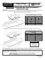
DIMENSIONS
inches cm
A 34-9/16 +
1/16 87.9 + 0.2
B20-3/8+
1/16 51.9 + 0.2
C 2-1/8 min. 5.4
D 4-1/8 min. clear 10.5
E 35-5/16 89.7
F 21 53.3
G3-3/4 9.5
INSTALLATION
INSTRUCTIONS
Radiant Cooktop
Models MEC5430 & MEC5536
403 WEST FOURTH STREET, NORTH D NEWTON, IA 50208
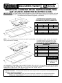
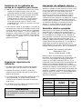
FIVE-ELEMENT RADIANT COOKTOPS
FOUR-ELEMENT RADIANT COOKTOPS
IMPORTANT - SAVE FOR THE LOCAL ELECTRICAL
INSPECTOR’S USE
IMPORTANT: Installation should be performed only by an authorized Maytag Service Contractor or other qualified
installer. Read safety precautions in the Use & Care Manual before using this appliance.
(Dimensions shown in both inches and centimeters)
DIMENSIONS
inches cm
A 29-1/16 +
1/16 74.0 + 0.2
B20-3/8+
1/16 51.9 + 0.2
C 2-1/8 min. 5.4
D 4-1/8 min. clear 10.5
E 29-15/16 76.0
F 21 53.3
G3-3/4 9.5
UNITS PROVIDED WITH 1/2² (1.3 cm) I.D. FLEXIBLE CABLE 48² (121.9 cm) LONG WITH 6² (15.2 cm) WIRE LEADS
AT END, FURNISHED AND INSTALLED BY MANUFACTURER (CONNECT TO 240/120 VOLT ELECTRICAL SERVICE).
NOTE: “D” is clearance needed for unit depth measure down from top of countertop. Typical for all units.
D
A
B
G
C
F
E
D
IMPORTANT
CUTOUT
DIMENSIONS
ARE CRITICAL
A
B
C
D
E
F
G
A
C
D
B
G
E
F

2
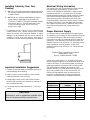
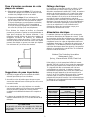
Installing Cabinetry Over Your
Cooktop
A= 30²
²²
² (76.2 cm) minimum clearance between the top of
the cooktop and the bottom of an unprotected wood
or metal cabinet.
A= 24²
²²
² (60.96 cm) minimum when bottom of wood or
metal cabinet is protected by not less than 1/4²
(0.635 cm). FLAME RETARDANT millboard covered
with not less than no. 28 MSG sheet steel, 0.015²
(0.038 cm) stainless steel, 0.024² (0.061 cm)
aluminum or copper.
* To eliminate the risk of burns or fire by reaching over
heated surface units, cabinet storage space located
above the surface units should be avoided. If cabinet
storage is to be provided, the risk can be reduced by
installing a range hood that projects horizontally a
minimum of 5 inches beyond the bottom of the cabinets.
Important Installation Suggestions
1. Chamfer all exposed edges of decorative laminate to
prevent damage from chipping.
2. Radius corners of cutout and file to insure smooth
edges and prevent corner cracking.
3. Rough edges, inside corners which have not been
rounded and forced fits can contribute to cracking of
the countertop laminate.
4. Countertop must be supported within 3² (7.62 cm) of
cutout.
CAUTION
Warranty is void on equipment installed other
than as recommended by manufacturer.
Electrical Wiring Information
The neutral of this unit is grounded to the frame through
the solid copper grounding wire. If used on new
branch-circuit installations (1996 NEC), mobile homes,
recreational vehicles, or in an area where local codes
prohibit grounding through the neutral conductor, untwist
or disconnect the solid copper wire and connect the
ground wire to ground in accordance with local code.
Connect the white neutral to the service neutral. Connect
all wires to the branch circuit with approved connectors.
Use copper or aluminum wire. If aluminum wire is used,
use connectors recognized for joining aluminum to
copper.
Proper Electrical Supply
You must provide an adequate electrical supply system
as required for your cooktop. All wire connections must be
in accordance with local codes and properly insulated.
Check with local utility for governing electrical codes and
ordinances. In the absence of local electrical codes, the
National Electrical Code, NFPA No. 70, governing electric
range installations must be followed. A copy of the
National Electrical Code, NFPA No. 70, can be obtained
by writing to:
National Fire Protection Association
Batterymarch Park
Quincy, Massachusetts 02269
A three-wire, single phase, A.C. 120/240 volt 60 cycle
electrical system (properly circuit protected to meet Local
Codes of NFPA No. 70) must be provided. Unit must be
properly grounded in accordance with local wiring code.
The chart below recommends the minimum circuit
protector and wire size if the appliance is the only unit on
the circuit. If smaller sizes of wire are used, the unit
efficiency will be reduced and a fire hazard may be
created. It is advisable that the electrical wiring and
hookup be accomplished by a competent electrician.
RECOMMENDED MINIMUM
K.W. RATING CIRCUIT PROTECTION WIRE SIZE
ON SERIAL PLATE IN AMPRES (AWG)
0-4.8 20 12
4.9 - 6.9 30 10
7.0 - 9.9 40 8
10.0 - 11.9 50 8
12.0 - 14.9 60 6

3
Notice To Installer
Follow accompanying instruction carefully.
CAUTION
Neverusea metalblade topry knoboff. Ifknob
cannot be easily removed, tuck folds of a
dishtowelunderknobskirtandpullupwardwith
steady, even pressure.
Preparation Of Countertop
The cutout in the countertop into which the appliance is to
be installed should be prepared according to the cutout
dimensions given on page 1 of these instructions.
CAUTION
Cutout dimensions are critical. Dimensions
must bemeasured and cut accuratelyto within
+ 1/16² (.16 cm) to insure proper fit.
Installation Of Appliance
1. Remove the cooktop from the carton and place it
upside down over two soft pads making sure control
knobs do not interfere with any surface.
2. Provide cutout in countertop as required per page 1.
3. Place unit in the cutout.
4. Make electrical wire connection to unit. Consult local
codes for proper power hook-up.
5. Test to insure control knobs operate all elements
properly.
Page is loading ...
Page is loading ...
Page is loading ...
Page is loading ...
Page is loading ...
Page is loading ...
-
 1
1
-
 2
2
-
 3
3
-
 4
4
-
 5
5
-
 6
6
-
 7
7
-
 8
8
-
 9
9


Ask a question and I''ll find the answer in the document
Finding information in a document is now easier with AI
in other languages
Related papers
-
Maytag MEC5536BAB14 Installation guide
-
Maytag MEC4436AAC - Chrome 36 Inch Electric Cooktop Installation Instructions Manual
-
-
-
-
-
-
Other documents
-
Summit SINC2220 SINC2220_PDFASSY.pdf
-
Jenn-Air JEC8536 User manual
-
Jenn-Air JEC9530 User manual
-
Jenn-Air JEC8536ADW Installation guide
-
-
-
-
-
Jenn-Air CVE3401B Installation guide
-